EP0094321A2 - Vorrichtung zum Verlegen von Leitungen bestimmt zur Aufnahme von elektrischen Kabeln - Google Patents
Vorrichtung zum Verlegen von Leitungen bestimmt zur Aufnahme von elektrischen Kabeln Download PDFInfo
- Publication number
- EP0094321A2 EP0094321A2 EP83400947A EP83400947A EP0094321A2 EP 0094321 A2 EP0094321 A2 EP 0094321A2 EP 83400947 A EP83400947 A EP 83400947A EP 83400947 A EP83400947 A EP 83400947A EP 0094321 A2 EP0094321 A2 EP 0094321A2
- Authority
- EP
- European Patent Office
- Prior art keywords
- wall
- plates
- base
- extension
- plate
- Prior art date
- Legal status (The legal status is an assumption and is not a legal conclusion. Google has not performed a legal analysis and makes no representation as to the accuracy of the status listed.)
- Granted
Links
Images


Classifications
-
- H—ELECTRICITY
- H02—GENERATION; CONVERSION OR DISTRIBUTION OF ELECTRIC POWER
- H02G—INSTALLATION OF ELECTRIC CABLES OR LINES, OR OF COMBINED OPTICAL AND ELECTRIC CABLES OR LINES
- H02G3/00—Installations of electric cables or lines or protective tubing therefor in or on buildings, equivalent structures or vehicles
- H02G3/02—Details
- H02G3/06—Joints for connecting lengths of protective tubing or channels, to each other or to casings, e.g. to distribution boxes; Ensuring electrical continuity in the joint
- H02G3/0608—Joints for connecting non cylindrical conduits, e.g. channels
-
- H—ELECTRICITY
- H02—GENERATION; CONVERSION OR DISTRIBUTION OF ELECTRIC POWER
- H02G—INSTALLATION OF ELECTRIC CABLES OR LINES, OR OF COMBINED OPTICAL AND ELECTRIC CABLES OR LINES
- H02G3/00—Installations of electric cables or lines or protective tubing therefor in or on buildings, equivalent structures or vehicles
- H02G3/02—Details
- H02G3/04—Protective tubing or conduits, e.g. cable ladders or cable troughs
- H02G3/0406—Details thereof
- H02G3/0418—Covers or lids; Their fastenings
Definitions
- the present invention relates to a device for installing conduits intended to accommodate electric cables, and more specifically conduits of the self-supporting plate type with a flat base, side walls and a cover, a device making it possible to obtain greater rigidity of the self-supporting trays for cables, with a uniformly distributed load, these trays being placed on separate supports, which has the result of reducing the flexions which they undergo as well in the transverse direction as in the longitudinal direction.
- the invention makes it possible to carry out an easy and effective coupling of the plates arranged successively with minimal use of accessories and tools, both with alignments at the same level as at different levels.
- each side wall from the trays has, on its upper part, a flat tubular extension parallel to the base, this extension, oriented in the inward direction, forming with the corresponding wall an external groove provided to receive a flange, also re-entrant, of the side of the cover of the tray, this cover being applied by pressure thanks to the elasticity of its sides and of the wall of the tray itself.
- Said extension gives the plate a high resistance to bending, both in the transverse direction and in the longitudinal direction.
- the groove formed between the extension of each wall of the tray and the wall itself is preferably of angular section, with its upper side - parallel to the base and its other side in an oblique position, the rim of the cover corresponding to this section.
- the longitudinal coupling of contiguous plates is carried out by means of profiles constituted by a flat wall which can be leaned simultaneously against the internal face of the wall of two contiguous plates, and by two fins, upper and lower, the the first is coupled to the re-entrant extension of the wall of the plates and the second is supported on the base of the plates, where it is fixed by screwing.
- the assembly of the upper fin of the coupling profile with the corresponding upper extension of the plate is obtained by backing between the convex and concave parts of said elements, a longitudinal rib of the face lower of said extension forming part of said concave part, which gives greater rigidity to the plate.
- the attachment of the lower fin of the coupling profiles on the base of the plates is carried out, according to the invention, by means of screws passing through elongated orifices in the longitudinal direction for said fin and in the transverse direction for the plate.
- the coupling profiles When two contiguous plates form an angle, provision is made for the coupling profiles to consist of two parts that can be adjusted in angular connection by means of an articulation fin for their walls, the corresponding fins being assembled by means of circular concave parts. crossed by a bolt designed as an axis of rotation, said sections allowing the coupling of plates with bases in angular connection in dihedral.
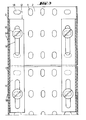
- Fig. 1 is a plan view of a section of plate for electrical conduits according to the invention, in which is shown a longitudinal half provided with a cover.
- Fig. 2 is a cross-sectional view of a plate along the line II-II of FIG. 1.
- Fig. 3 is a plan view of two plates in coupling along a section made along line III-III of FIG. 2.
- Fig. 4 is a perspective view of a coupling profile for the straight alignment of two plates.
- Fig. 5 is a perspective view of a coupling profile for the angular alignment of two plates at different levels.
- Fig. 6 is a view in longitudinal section of an angular coupling profile according to FIG. 5, the two component parts being aligned.
- the device for installing pipes or conduits intended to accommodate electric cables which is the subject of the present invention consists of trays 1 with a flat base 2 and side walls 3 of a relatively reduced height, provided with a cover 4.
- Each of the walls 3 of the plates 1 has, on its upper part, from a re-entrant inflection 5, a flat tubular extension 6, parallel to the base 2, which, while giving greater rigidity to the plate 1, serves to support for the part 7 of said cover 4.
- the inflection 5 and the extension 6 define an angular groove 8 provided to receive a re-entrant flange 9 of the sidewall 10 of the cover 4, the section of the two elements being complementary, which makes it possible to get, as seen in fig. 2, efficient mating.
- the mounting of the cover 4 is carried out by pressure thanks to a certain elasticity of the sides 10 and of the wall 3 itself, the planes of the side 10 and of the wall 3 of the tray 1 being aligned with each other.
- the rim 9 has an angular section corresponding to that of the groove 8, with the upper side parallel to the base and the other side in an oblique position.
- the base 2 of the plates has orifices 11 allowing the passage of flanges for fixing the bundles of conductors housed in these plates.
- profiles 12 are used (see fig. 4)., Having a planar wall 13 to lean against the internal face of the side walls 3 of the plates, a lower fin 14 at right angles to rest on the base 2 and an upper fin 15 forming an arc with three planes 15a, 15b and 15c which is applied against the extension 6 of said plates.
- the profiles 12 are fixed to the base 2 of the plates 1 by means of the screws 16 with nut 17 passing through the elongated orifices 18 of the base 2, in the transverse direction, and other elongated orifices 19 of the profile 12 in the direction longitudinal, which makes it possible to obtain a perfect fixing for any plane longitudinal connection of the two plates.
- the two plates 1A and 1B are coupled by means of the profiles 12, with the particularity that, to carry out the coupling, it is not necessary to separate the plates to thread them onto the profiles 12, since these profiles 12 are applicable frontally by simple pressure exerted in the transverse direction, which facilitates mounting.
- said coupling, between plates 1 and profiles 12, is effected with application of the arched upper fin 15 of said profiles to a lower concavity of the tubular extension 6 of the plates, this extension having, for this purpose, a longitudinal rib 20 which, at the same time, serves to increase the rigidity of the plate 1, as seen in FIG. 2.
- coupling profiles 12A (see fig. 4 and 5), which consist of two parts formed like the sections 12 already mentioned, with the arcuate fin constituted only by two planes 15a and 15b, but having a fin 21 and 22 respectively, in longitudinal extension of the wall 13.
- These fins form a complementary fitting 23 and 24 with a central orifice by which passes a screw 25 with nut 26, as the axis of rotation, so that the force of the joint is developed by the sockets 23 and 24.
Landscapes
- Engineering & Computer Science (AREA)
- Architecture (AREA)
- Civil Engineering (AREA)
- Structural Engineering (AREA)
- Details Of Indoor Wiring (AREA)
- Laying Of Electric Cables Or Lines Outside (AREA)
- Insulated Conductors (AREA)
- Electric Cable Installation (AREA)
Priority Applications (1)
| Application Number | Priority Date | Filing Date | Title |
|---|---|---|---|
| AT83400947T ATE26365T1 (de) | 1982-05-11 | 1983-05-10 | Vorrichtung zum verlegen von leitungen bestimmt zur aufnahme von elektrischen kabeln. |
Applications Claiming Priority (2)
| Application Number | Priority Date | Filing Date | Title |
|---|---|---|---|
| ES51206282 | 1982-05-11 | ||
| ES512062 | 1982-05-11 |
Publications (3)
| Publication Number | Publication Date |
|---|---|
| EP0094321A2 true EP0094321A2 (de) | 1983-11-16 |
| EP0094321A3 EP0094321A3 (en) | 1984-11-21 |
| EP0094321B1 EP0094321B1 (de) | 1987-04-01 |
Family
ID=8484122
Family Applications (1)
| Application Number | Title | Priority Date | Filing Date |
|---|---|---|---|
| EP83400947A Expired EP0094321B1 (de) | 1982-05-11 | 1983-05-10 | Vorrichtung zum Verlegen von Leitungen bestimmt zur Aufnahme von elektrischen Kabeln |
Country Status (3)
| Country | Link |
|---|---|
| EP (1) | EP0094321B1 (de) |
| AT (1) | ATE26365T1 (de) |
| DE (1) | DE3370725D1 (de) |
Cited By (5)
| Publication number | Priority date | Publication date | Assignee | Title |
|---|---|---|---|---|
| WO2002031939A1 (en) * | 2000-10-13 | 2002-04-18 | Alan Dick & Co. Ltd. | Cable tray |
| EP2112732A1 (de) * | 2008-04-25 | 2009-10-28 | Unex Aparellaje Electrico S.L. | Laufbahn für elektrische Leiter und auf besagte Laufbahn anwendbare Halterung |
| EP2112733A1 (de) * | 2008-04-25 | 2009-10-28 | Unex Aparellaje Electrico S.L. | Laufbahn für elektrische Leiter und auf besagte Laufbahn anwendbare Kupplung |
| EP2781814A1 (de) * | 2013-03-19 | 2014-09-24 | J. van Walraven Holding B.V. | Unterstützungskanal |
| NL2010618C2 (en) * | 2013-04-11 | 2014-10-14 | Walraven Holding Bv J Van | Pipe support part. |
Family Cites Families (7)
| Publication number | Priority date | Publication date | Assignee | Title |
|---|---|---|---|---|
| FR1262928A (fr) * | 1960-07-19 | 1961-06-05 | Burndy Corp | Caniveau de support |
| FR1351262A (fr) * | 1963-03-20 | 1964-01-31 | Rieth & Co Fa | Gouttière-support pour câbles et conduites |
| US3347275A (en) * | 1965-10-07 | 1967-10-17 | Wiremold Co | Raceway |
| BE794171A (fr) * | 1972-02-01 | 1973-07-17 | Planet Wattohm Sa | Chemin de cables |
| FR2406327A1 (fr) * | 1977-10-17 | 1979-05-11 | Planet Wattohm Sa | Dispositif d'encliquetage du couvercle pour goulottes formant chemins de cables ou ensembles analogues |
| ES238422Y (es) * | 1978-09-28 | 1979-04-01 | Aparellaje Electrico, S.A. | Dispositivo para el acoplamiento de canalizaciones electri- cas |
| NL183618C (nl) * | 1980-10-08 | 1988-12-01 | Stago Bv | Koppelingssysteem voor in elkaars verlengde liggende kabelgoten. |
-
1983
- 1983-05-10 AT AT83400947T patent/ATE26365T1/de not_active IP Right Cessation
- 1983-05-10 DE DE8383400947T patent/DE3370725D1/de not_active Expired
- 1983-05-10 EP EP83400947A patent/EP0094321B1/de not_active Expired
Cited By (5)
| Publication number | Priority date | Publication date | Assignee | Title |
|---|---|---|---|---|
| WO2002031939A1 (en) * | 2000-10-13 | 2002-04-18 | Alan Dick & Co. Ltd. | Cable tray |
| EP2112732A1 (de) * | 2008-04-25 | 2009-10-28 | Unex Aparellaje Electrico S.L. | Laufbahn für elektrische Leiter und auf besagte Laufbahn anwendbare Halterung |
| EP2112733A1 (de) * | 2008-04-25 | 2009-10-28 | Unex Aparellaje Electrico S.L. | Laufbahn für elektrische Leiter und auf besagte Laufbahn anwendbare Kupplung |
| EP2781814A1 (de) * | 2013-03-19 | 2014-09-24 | J. van Walraven Holding B.V. | Unterstützungskanal |
| NL2010618C2 (en) * | 2013-04-11 | 2014-10-14 | Walraven Holding Bv J Van | Pipe support part. |
Also Published As
| Publication number | Publication date |
|---|---|
| ATE26365T1 (de) | 1987-04-15 |
| DE3370725D1 (en) | 1987-05-07 |
| EP0094321A3 (en) | 1984-11-21 |
| EP0094321B1 (de) | 1987-04-01 |
Similar Documents
| Publication | Publication Date | Title |
|---|---|---|
| FR2656203A1 (fr) | Tiroir demontable. | |
| FR2786846A3 (fr) | Collier de fixation de tuyau | |
| EP0094321A2 (de) | Vorrichtung zum Verlegen von Leitungen bestimmt zur Aufnahme von elektrischen Kabeln | |
| EP1108452B1 (de) | Verbindungselement zum Kuppeln eines Stiefels mit einem Snowboard | |
| FR2748559A1 (fr) | Dispositif de fixation d'un groupe moto-ventilateur sur un echangeur de chaleur, notamment de vehicule automobile | |
| FR2683566A1 (fr) | Dispositif de support en tole pour un profile horizontal destine a recevoir un faux plafond. | |
| CA2749382C (fr) | Platine de fixation reglable pour tendre sans deformation par des cables une nappe souple | |
| EP0473481A1 (de) | Befestigungsgehäuse mit variablem Achsabstand für elektrisches Gerät | |
| FR2488742A1 (fr) | Coude d'assemblage pour pieces de canalisation de cables electriques | |
| FR2854112A1 (fr) | Ensemble de barres de toit pour un vehicule automobile | |
| FR2698648A1 (fr) | Poutrelle cintrable et coffrages courbes faisant application de telles poutrelles. | |
| FR2956257A1 (fr) | Organe de pre-assemblage d'un chassis d'appareil electrique sur une goulotte electrique, appareil electrique comportant un tel organe de pre -assemblage, et procede de fixation d'un tel organe de pre-assemblage sur le chassis d'un tel appareil electrique | |
| FR2717635A1 (fr) | Support universel pour jeu de barres conductrices se fixant à plat . | |
| FR2509868A1 (fr) | Appareil de mesure electrique du type modulaire | |
| CH617256A5 (en) | Lamp | |
| EP1150404B1 (de) | Gehäuse für elektrische Geräte mit Kabeldurchführung | |
| FR2780113A1 (fr) | Fixation pour pied de lit | |
| FR2974457A1 (fr) | Bloc multi-appareillages equipe d'un connecteur mobile en translation | |
| FR2547858A1 (fr) | Echelle en elements demontables et emboitables, autorisant une reduction volumetrique, lors du transport ou de l'inutilisation | |
| FR2734422A1 (fr) | Support d'appareil electrique pour goulotte a rails | |
| EP0216719B1 (de) | Leuchte, insbesondere Halogenlampe für sehr niedrige Spannung | |
| FR2633343A1 (fr) | Dispositif de fixation et de retenue pour fixer des eviers metalliques sur des meubles | |
| BE890361A (fr) | Meuble | |
| FR2781616A1 (fr) | Boite d'encastrement susceptible d'etre jumelee avec une autre, notamment pour appareillage electrique | |
| FR2616822A1 (fr) | Dispositif de fixation d'un panneau sur des montants |
Legal Events
| Date | Code | Title | Description |
|---|---|---|---|
| PUAI | Public reference made under article 153(3) epc to a published international application that has entered the european phase |
Free format text: ORIGINAL CODE: 0009012 |
|
| AK | Designated contracting states |
Designated state(s): AT BE CH DE FR GB IT LI LU NL SE |
|
| PUAL | Search report despatched |
Free format text: ORIGINAL CODE: 0009013 |
|
| AK | Designated contracting states |
Designated state(s): AT BE CH DE FR GB IT LI LU NL SE |
|
| 17P | Request for examination filed |
Effective date: 19850211 |
|
| ITF | It: translation for a ep patent filed | ||
| GRAA | (expected) grant |
Free format text: ORIGINAL CODE: 0009210 |
|
| AK | Designated contracting states |
Kind code of ref document: B1 Designated state(s): AT BE CH DE FR GB IT LI LU NL SE |
|
| REF | Corresponds to: |
Ref document number: 26365 Country of ref document: AT Date of ref document: 19870415 Kind code of ref document: T |
|
| PG25 | Lapsed in a contracting state [announced via postgrant information from national office to epo] |
Ref country code: SE Effective date: 19870430 |
|
| REF | Corresponds to: |
Ref document number: 3370725 Country of ref document: DE Date of ref document: 19870507 |
|
| PLBE | No opposition filed within time limit |
Free format text: ORIGINAL CODE: 0009261 |
|
| STAA | Information on the status of an ep patent application or granted ep patent |
Free format text: STATUS: NO OPPOSITION FILED WITHIN TIME LIMIT |
|
| 26N | No opposition filed | ||
| ITTA | It: last paid annual fee | ||
| EPTA | Lu: last paid annual fee | ||
| REG | Reference to a national code |
Ref country code: GB Ref legal event code: IF02 |
|
| PGFP | Annual fee paid to national office [announced via postgrant information from national office to epo] |
Ref country code: GB Payment date: 20020419 Year of fee payment: 20 |
|
| PGFP | Annual fee paid to national office [announced via postgrant information from national office to epo] |
Ref country code: NL Payment date: 20020423 Year of fee payment: 20 Ref country code: CH Payment date: 20020423 Year of fee payment: 20 |
|
| PGFP | Annual fee paid to national office [announced via postgrant information from national office to epo] |
Ref country code: FR Payment date: 20020430 Year of fee payment: 20 |
|
| PGFP | Annual fee paid to national office [announced via postgrant information from national office to epo] |
Ref country code: AT Payment date: 20020513 Year of fee payment: 20 |
|
| PGFP | Annual fee paid to national office [announced via postgrant information from national office to epo] |
Ref country code: LU Payment date: 20020607 Year of fee payment: 20 |
|
| PGFP | Annual fee paid to national office [announced via postgrant information from national office to epo] |
Ref country code: BE Payment date: 20020628 Year of fee payment: 20 |
|
| PGFP | Annual fee paid to national office [announced via postgrant information from national office to epo] |
Ref country code: DE Payment date: 20020730 Year of fee payment: 20 |
|
| PG25 | Lapsed in a contracting state [announced via postgrant information from national office to epo] |
Ref country code: LI Free format text: LAPSE BECAUSE OF EXPIRATION OF PROTECTION Effective date: 20030509 Ref country code: GB Free format text: LAPSE BECAUSE OF EXPIRATION OF PROTECTION Effective date: 20030509 Ref country code: CH Free format text: LAPSE BECAUSE OF EXPIRATION OF PROTECTION Effective date: 20030509 |
|
| PG25 | Lapsed in a contracting state [announced via postgrant information from national office to epo] |
Ref country code: NL Free format text: LAPSE BECAUSE OF EXPIRATION OF PROTECTION Effective date: 20030510 Ref country code: LU Free format text: LAPSE BECAUSE OF EXPIRATION OF PROTECTION Effective date: 20030510 Ref country code: AT Free format text: LAPSE BECAUSE OF EXPIRATION OF PROTECTION Effective date: 20030510 |
|
| REG | Reference to a national code |
Ref country code: CH Ref legal event code: PL |
|
| BE20 | Be: patent expired |
Owner name: *APARELLAJE ELECTRICO S.A. Effective date: 20030510 |
|
| REG | Reference to a national code |
Ref country code: GB Ref legal event code: PE20 |
|
| NLV7 | Nl: ceased due to reaching the maximum lifetime of a patent |
Effective date: 20030510 |