EP0094326B1 - Befestigungsanordnung eines Apparates in einem Kernreaktor - Google Patents
Befestigungsanordnung eines Apparates in einem Kernreaktor Download PDFInfo
- Publication number
- EP0094326B1 EP0094326B1 EP83400970A EP83400970A EP0094326B1 EP 0094326 B1 EP0094326 B1 EP 0094326B1 EP 83400970 A EP83400970 A EP 83400970A EP 83400970 A EP83400970 A EP 83400970A EP 0094326 B1 EP0094326 B1 EP 0094326B1
- Authority
- EP
- European Patent Office
- Prior art keywords
- flange
- slab
- elastically yieldable
- fixing device
- caracterised
- Prior art date
- Legal status (The legal status is an assumption and is not a legal conclusion. Google has not performed a legal analysis and makes no representation as to the accuracy of the status listed.)
- Expired
Links
- 230000003068 static effect Effects 0.000 claims 1
- 230000002159 abnormal effect Effects 0.000 description 1
- 238000004873 anchoring Methods 0.000 description 1
- 238000013016 damping Methods 0.000 description 1
- 230000001066 destructive effect Effects 0.000 description 1
- 230000005284 excitation Effects 0.000 description 1
- 239000012530 fluid Substances 0.000 description 1
- 238000009434 installation Methods 0.000 description 1
- 230000010355 oscillation Effects 0.000 description 1
- 230000002093 peripheral effect Effects 0.000 description 1
- 230000035939 shock Effects 0.000 description 1
Images

Classifications
-
- G—PHYSICS
- G21—NUCLEAR PHYSICS; NUCLEAR ENGINEERING
- G21C—NUCLEAR REACTORS
- G21C13/00—Pressure vessels; Containment vessels; Containment in general
- G21C13/02—Details
- G21C13/024—Supporting constructions for pressure vessels or containment vessels
-
- Y—GENERAL TAGGING OF NEW TECHNOLOGICAL DEVELOPMENTS; GENERAL TAGGING OF CROSS-SECTIONAL TECHNOLOGIES SPANNING OVER SEVERAL SECTIONS OF THE IPC; TECHNICAL SUBJECTS COVERED BY FORMER USPC CROSS-REFERENCE ART COLLECTIONS [XRACs] AND DIGESTS
- Y02—TECHNOLOGIES OR APPLICATIONS FOR MITIGATION OR ADAPTATION AGAINST CLIMATE CHANGE
- Y02E—REDUCTION OF GREENHOUSE GAS [GHG] EMISSIONS, RELATED TO ENERGY GENERATION, TRANSMISSION OR DISTRIBUTION
- Y02E30/00—Energy generation of nuclear origin
- Y02E30/30—Nuclear fission reactors
Definitions
- the present invention relates to a device for fixing one or more essential devices contained in a nuclear reactor.
- Some nuclear power plant boilers are made up of a large enclosure enclosing the reactor core and various devices such as primary pumps, intermediate exchangers, command or control apparatus for the core.
- This enclosure of the reactor can be covered, at its upper part, by a rigid slab and the various apparatuses of the reactor can be arranged in the enclosure by being fixed, by their upper part, to this rigid slab.
- These devices are subjected to significant forces, slow movements caused for example by thermal shocks and vibrations caused for example by fluid flows.
- thermal shocks and vibrations caused for example by fluid flows.
- the movements of the ground are transmitted to the rigid slab which transmits significant forces and movements to the devices that are fixed on it.
- An earthquake can therefore damage the rigid slab, the fastening elements of the devices on the rigid slab, the devices themselves, or even the various connections of these devices to each other, which can lead to ruptured pipes or other damage.
- the invention relates to a device making it possible to limit the destructive effects for the devices or for the slab, during an earthquake.
- the present invention therefore relates to a device for fixing an appliance placed in a nuclear reactor, in which the appliance passes through a rigid slab for closing the nuclear reactor, and is suspended from this slab by a flange in the form of a circumferential radial widening. - rential provided at the upper part of said device and by elastic elements.
- the fixing device comprises a first series of elastic elements mounted between one of the faces of the flange and the upper face of the slab and a second series of elastic elements also mounted between the other side of the flange and a counter flange itself fixed on the slab, so as to hold the flange (6) of the apparatus between the slab and the counter flange in an elastic manner vertically in both directions .
- each elastic element is composed of a stack of conical elastic washers.
- FIG. 1 there is a slab 1 for closing a fast neutron nuclear reactor.
- This slab is intended to support various devices necessary for the operation of the reactor.
- the slab 1 has an opening 4 and the device 2 can be installed by bringing it above the slab 1 and introducing its body 5 into the opening 4.
- the device 2 has, at its upper part 3, a radial enlargement 6 which is fixed on the slab 1.
- the invention relates more precisely to the arrangement making it possible to establish the connection between the radial enlargement 6 of the device 2 and the slab 1.
- This connecting means must be capable of elastically damping the movements of the slab 1 which may occur during an earthquake.
- FIG. 2 which relates to a particular embodiment of the invention, there is the apparatus 2, the lower part 5 of which is threaded through the opening 4 of the slab 1 and the upper part of which 3 has a flange 6 in the form of a widening ra dial.
- This flange 6 has two parallel radial faces 9 and 11.
- the lower face 9 of the flange 6 comes to rest vertically on a part 13 rigidly connected to the slab 1.
- the upper face 11 of the flange 6 comes to rest vertically upwards on a part 12 which is also rigidly linked to the slab 1.
- the contact between the flange 6 and the parts 12 and 13 is however not made directly but by means of a series of springs 8 and a series of springs 10.
- the flange 6 also comprises, on its peripheral part, a spherical surface 16 engaged with minimum clearance in a vertical bore 17 formed in the support part 13.
- the device 2 can both move vertically relative to the slab 1 and move in rotation thanks to the ball joint type 16,17.
- the slab 1 must constitute a sealed cover for the reactor, it is useful to provide, between the apparatus 2 and the slab 1, a seal.
- This seal is produced here, in a manner known per se, using a bellows 18 disposed vertically between the body 5 of the device 2 and the opening 4 of the slab 1, this bellows 18 being connected in a sealed manner, on the one hand to the device 2, on the other hand to the panel 1 or to the support part 13 itself linked in a sealed manner to the panel 1.
- the devices 2 which are thus fixed on the slab 1 are generally of very large mass, and the series of springs 8 and 10 which establish the elastic connection between the device 2 and the slab 1 must therefore withstand loads. very high.
- the springs 8 and 10 are preferably produced using a stack of a number of conical elastic washers. These washers are commonly designated as being of the "Belleville" type. Realizing the series of springs 8 and 10 using a stack of elastic washers is very advantageous because it makes it possible to form springs having exactly all the desired characteristics, of length, resistance, elasticity, etc. ..., playing only on the number of washers and on the combination of washers stacked in the same direction or in opposite directions.
- the flange 6 of the device 2 is of circular shape, and, consequently, the two series of springs 8 and 10 arranged on either side of the flange are located on concentric circles of diameters D1 and D2 different. In this way, it can be seen that no elastic element 8 is coaxial with the opposite elastic element 10. This therefore makes it possible to produce a flange 6 of smaller bulk and weight.
- the elastic element 8 made up of stacked washers, is arranged in a blind hole 19 made in the flange 6.
- the stack of elastic washers 8 is thus mounted in the flange 6 before the installation of the device 2, and is held in position by means of a screw 20 axially passing through the elastic washers 8 and coming to be screwed into the bottom of the blind hole 19.
- the length of the stack of elastic washers 8, in the absence of any load must be greater than the length of the blind hole 19, so that, when the flange 6 is placed above the support piece 13, it creates a space 14 allowing the springs 8 to establish the elastic connection between the flange 6 and the support 13, and consequently between the device 2 and the slab 1.
- the elastic element 10 is not mounted completely made identical to elastic element 8, although this amounts to exactly the same. It can be seen that the elastic element 10, also consisting of a stack of elastic washers, has its lower part engaged in a blind hole 21 formed on the upper part of the flange 6, and at its other end engaged in a blind hole 22 provided in the counter-flange 12. This constructive arrangement is justified mainly by considerations of space.
- the length of the screws 20 can be chosen so that, when they are mounted, they each create, in the stack of washers 8 corresponding, a certain predetermined prestress. In this way, the device 2 is positioned more precisely and more rigorously relative to the slab, 1 while remaining linked with a certain elasticity. It is also, of course, possible to create a similar prestress in the upper elastic elements 10. One can create in these elastic elements 8 a prestress slightly greater than the load supported by these elements 8 when the device rests on the slab. Under these conditions, the connection between the device and the slab behaves like a rigid connection in abnormal operating mode, and nevertheless has a certain elasticity in the event of overload due, for example, to an earthquake.
- the number of elastic elements 8 or 10 disposed on the flange 6 is quite large, it may be preferable to replace the blind holes 19, 21, 22 formed in the flange or the counter-flange with annular grooves provided in the same way in the flange or counterflange and of the same diameter D i and D 2 .
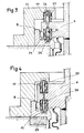
- Figure 3 shows an alternative embodiment.
- the stacks of washers 8 and 10 are maintained by means of rods 23 passing through the washers and screwed into the bottom of the corresponding blind holes.
- the outer end of each rod 23 has a threaded hole in which is aimed a screw 24 which retains the washers by exerting on them, possibly, a prestress.
- the elastic elements 8 and 10 are located on concentric circles of the same diameter D i .
- the elastic element 8 is placed in a hole in the flange 6, and the elastic element 10 is placed in a hole in the counter flange 12.
- Figure 4 is an alternative embodiment of Figure 3 in which of the elastic elements 8 and 10 are both arranged in holes made in the flange 6.
- the support piece 13 can be linked directly to the slab 1, but can also be linked by means of an anchoring piece 25.
- the counter-flange 12 can be linked directly to the slab 1 but can also be mounted on the support part 13, as shown in FIG. 4.
- the fixing device according to the invention makes it possible to mount the device on the slab with a minimum of difficulty and great reliability. It also allows the dismantling and changing of the elastic elements 8 or 10 without completely removing the device from the slab.
Landscapes
- Physics & Mathematics (AREA)
- Engineering & Computer Science (AREA)
- Plasma & Fusion (AREA)
- General Engineering & Computer Science (AREA)
- High Energy & Nuclear Physics (AREA)
- Vibration Prevention Devices (AREA)
Claims (12)
Applications Claiming Priority (2)
| Application Number | Priority Date | Filing Date | Title |
|---|---|---|---|
| FR8208219 | 1982-05-12 | ||
| FR8208219A FR2526990B1 (fr) | 1982-05-12 | 1982-05-12 | Dispositif de fixation d'un appareil dans une installation de centrale nucleaire |
Publications (2)
| Publication Number | Publication Date |
|---|---|
| EP0094326A1 EP0094326A1 (de) | 1983-11-16 |
| EP0094326B1 true EP0094326B1 (de) | 1985-09-11 |
Family
ID=9273939
Family Applications (1)
| Application Number | Title | Priority Date | Filing Date |
|---|---|---|---|
| EP83400970A Expired EP0094326B1 (de) | 1982-05-12 | 1983-05-11 | Befestigungsanordnung eines Apparates in einem Kernreaktor |
Country Status (3)
| Country | Link |
|---|---|
| EP (1) | EP0094326B1 (de) |
| DE (1) | DE3360775D1 (de) |
| FR (1) | FR2526990B1 (de) |
Families Citing this family (4)
| Publication number | Priority date | Publication date | Assignee | Title |
|---|---|---|---|---|
| FR2531801B1 (fr) * | 1982-08-13 | 1986-08-01 | Electricite De France | Structure de supportage anti-sismique pour bloc pile de reacteur nucleaire du type a neutrons rapides |
| US4786461A (en) * | 1983-09-30 | 1988-11-22 | Westinghouse Electric Corp. | Reactor internals hold down spring |
| FR2591020B1 (fr) * | 1985-12-03 | 1988-01-15 | Jeumont Schneider | Dispositif pour la liaison anti-seismes entre le bas de pompe et la sphere d'une centrale nucleaire |
| CN114033903B (zh) * | 2021-11-25 | 2023-07-04 | 无锡艾尔特石化机械有限公司 | 一种液体管道法兰 |
Family Cites Families (6)
| Publication number | Priority date | Publication date | Assignee | Title |
|---|---|---|---|---|
| US2890009A (en) * | 1955-07-13 | 1959-06-09 | Combustion Eng | Vessel support |
| FR1564507A (de) * | 1967-11-21 | 1969-04-25 | ||
| US3746292A (en) * | 1971-05-29 | 1973-07-17 | Gen Electric | Vessell stabilization system |
| DE2424518C2 (de) * | 1974-05-20 | 1975-12-18 | Kraftwerk Union Ag, 4330 Muelheim | Kernreaktoranlage |
| FR2300253A1 (fr) * | 1975-02-06 | 1976-09-03 | Commissariat Energie Atomique | Dispositif |
| FR2483670A1 (fr) * | 1980-06-02 | 1981-12-04 | Stein Industrie | Dispositif de supportage antisismique d'un appareil baignant dans le bain de metal alcalin liquide entourant un reacteur nucleaire a neutrons rapides |
-
1982
- 1982-05-12 FR FR8208219A patent/FR2526990B1/fr not_active Expired
-
1983
- 1983-05-11 DE DE8383400970T patent/DE3360775D1/de not_active Expired
- 1983-05-11 EP EP83400970A patent/EP0094326B1/de not_active Expired
Also Published As
| Publication number | Publication date |
|---|---|
| FR2526990A1 (fr) | 1983-11-18 |
| DE3360775D1 (en) | 1985-10-17 |
| FR2526990B1 (fr) | 1986-05-02 |
| EP0094326A1 (de) | 1983-11-16 |
Similar Documents
| Publication | Publication Date | Title |
|---|---|---|
| EP0161978B1 (de) | Schwingungsdämpfungsvorrichtung für die Befestigung eines Rohres dessen Wandstärke klein ist im Verhältnis zum Durchmesser | |
| EP2212583B1 (de) | Auf elastomer basierende modulare vorrichtung für mehrachsige isolierung gegen vibration und stosswirkung | |
| EP0094326A1 (de) | Befestigungsanordnung eines Apparates in einem Kernreaktor | |
| FR2596839A1 (fr) | Support antivibration et son procede d'utilisation | |
| EP1697947A2 (de) | Verfahren zur begrenzung von leitungsbemühungen an einer kernreaktor-brennstoffbaugruppe und brennstoffbaugruppe | |
| EP0123599B1 (de) | Zerlegbare Befestigungsanordnung einer inneren Struktur in einer Hülle etwa einer Leitung oder eines Behälters | |
| FR3042901A1 (fr) | Dispositif de declenchement et d'insertion d'elements absorbants et/ou mitigateurs d'un reacteur nucleaire mettant en œuvre des elements flexibles et assemblage de combustible nucleaire comportant un tel dispositif | |
| EP4060206B1 (de) | Mechanische vorrichtung zum blockieren einer linearen bewegung zwischen zwei strukturen | |
| FR2997685A3 (fr) | Dispositif de decharge | |
| EP0055678A1 (de) | Vorrichtung zum Dämpfen von Schwingungen einer Maschine oder Konstruktion | |
| EP0128801B1 (de) | Anordnung zur Unterstützung einer Struktur auf einer Sockelstütze | |
| FR2994327B1 (fr) | Pieds reglables deformables pour chassis de ratelier de stockage pour assemblages combustibles nucleaires | |
| FR2531257A1 (fr) | Element combustible de reacteur nucleaire | |
| EP1293701B1 (de) | Schwingungsdämpfendes Lager und Schwingungsdämpfungseinrichtung mit solchem Lager | |
| FR2776745A1 (fr) | Dispositif de protection pour une tuyauterie sous pression placee dans une installation et application | |
| EP0112823A1 (de) | Durch erdstosswellen ausgelöstes absperrventil | |
| FR2812314A1 (fr) | Dispositif d'appui anti-soulevement pour ouvrages de genie civil | |
| FR2490306A1 (fr) | Amortisseur dynamique de vibrations | |
| FR2673453A1 (fr) | Plot de suspension en caoutchouc ou materiau elastique. | |
| FR2691636A1 (fr) | Vanne coupe-feu. | |
| EP0216665B1 (de) | Absorberstab für Schnellneutronenkernreaktoren | |
| EP0246143A1 (de) | Auflagervorrichtung für ein Auslassgehäuse einer in einem Kernreaktor aufgehängten Pumpe | |
| FR2766853A1 (fr) | Dispositif antivibratoire pour batiment | |
| CH366186A (fr) | Palier amortisseur de chocs pour appareils de précision autres que ceux appartenant au domaine de la technique de la mesure du temps | |
| EP0365374A1 (de) | Vorrichtung zur Handhabung einer Ausdehnungsmaschine für verschraubte Verbindungselemente |
Legal Events
| Date | Code | Title | Description |
|---|---|---|---|
| PUAI | Public reference made under article 153(3) epc to a published international application that has entered the european phase |
Free format text: ORIGINAL CODE: 0009012 |
|
| AK | Designated contracting states |
Designated state(s): BE DE GB IT LU NL |
|
| 17P | Request for examination filed |
Effective date: 19840119 |
|
| ITF | It: translation for a ep patent filed | ||
| GRAA | (expected) grant |
Free format text: ORIGINAL CODE: 0009210 |
|
| AK | Designated contracting states |
Designated state(s): BE DE GB IT LU NL |
|
| REF | Corresponds to: |
Ref document number: 3360775 Country of ref document: DE Date of ref document: 19851017 |
|
| PG25 | Lapsed in a contracting state [announced via postgrant information from national office to epo] |
Ref country code: LU Free format text: LAPSE BECAUSE OF NON-PAYMENT OF DUE FEES Effective date: 19860531 |
|
| PLBE | No opposition filed within time limit |
Free format text: ORIGINAL CODE: 0009261 |
|
| STAA | Information on the status of an ep patent application or granted ep patent |
Free format text: STATUS: NO OPPOSITION FILED WITHIN TIME LIMIT |
|
| 26N | No opposition filed | ||
| PGFP | Annual fee paid to national office [announced via postgrant information from national office to epo] |
Ref country code: DE Payment date: 19910423 Year of fee payment: 9 |
|
| PGFP | Annual fee paid to national office [announced via postgrant information from national office to epo] |
Ref country code: GB Payment date: 19910503 Year of fee payment: 9 |
|
| ITTA | It: last paid annual fee | ||
| PGFP | Annual fee paid to national office [announced via postgrant information from national office to epo] |
Ref country code: NL Payment date: 19910531 Year of fee payment: 9 |
|
| PGFP | Annual fee paid to national office [announced via postgrant information from national office to epo] |
Ref country code: BE Payment date: 19910619 Year of fee payment: 9 |
|
| PG25 | Lapsed in a contracting state [announced via postgrant information from national office to epo] |
Ref country code: GB Effective date: 19920511 |
|
| PG25 | Lapsed in a contracting state [announced via postgrant information from national office to epo] |
Ref country code: BE Effective date: 19920531 |
|
| BERE | Be: lapsed |
Owner name: NOVATOME Effective date: 19920531 |
|
| PG25 | Lapsed in a contracting state [announced via postgrant information from national office to epo] |
Ref country code: NL Effective date: 19921201 |
|
| GBPC | Gb: european patent ceased through non-payment of renewal fee |
Effective date: 19920511 |
|
| NLV4 | Nl: lapsed or anulled due to non-payment of the annual fee | ||
| PG25 | Lapsed in a contracting state [announced via postgrant information from national office to epo] |
Ref country code: DE Effective date: 19930202 |