EP0094330A1 - Schnürband, Verfahren zu dessen Behandlung und Einrichtung zur Ausführung dieses Verfahrens - Google Patents
Schnürband, Verfahren zu dessen Behandlung und Einrichtung zur Ausführung dieses Verfahrens Download PDFInfo
- Publication number
- EP0094330A1 EP0094330A1 EP83440026A EP83440026A EP0094330A1 EP 0094330 A1 EP0094330 A1 EP 0094330A1 EP 83440026 A EP83440026 A EP 83440026A EP 83440026 A EP83440026 A EP 83440026A EP 0094330 A1 EP0094330 A1 EP 0094330A1
- Authority
- EP
- European Patent Office
- Prior art keywords
- cord
- unitary
- cords
- treated
- threads
- Prior art date
- Legal status (The legal status is an assumption and is not a legal conclusion. Google has not performed a legal analysis and makes no representation as to the accuracy of the status listed.)
- Withdrawn
Links
- 238000000034 method Methods 0.000 title claims description 30
- 238000004519 manufacturing process Methods 0.000 claims abstract description 9
- 238000009434 installation Methods 0.000 claims description 16
- 239000004753 textile Substances 0.000 claims description 8
- 230000004927 fusion Effects 0.000 claims description 6
- 239000000835 fiber Substances 0.000 claims description 5
- 230000002093 peripheral effect Effects 0.000 claims 1
- 238000010408 sweeping Methods 0.000 claims 1
- 238000004804 winding Methods 0.000 claims 1
- 239000002966 varnish Substances 0.000 description 9
- 238000010438 heat treatment Methods 0.000 description 5
- 238000005520 cutting process Methods 0.000 description 4
- 229920000298 Cellophane Polymers 0.000 description 3
- 239000002184 metal Substances 0.000 description 3
- 238000007664 blowing Methods 0.000 description 2
- 238000001035 drying Methods 0.000 description 2
- 238000002844 melting Methods 0.000 description 2
- 230000008018 melting Effects 0.000 description 2
- 239000000203 mixture Substances 0.000 description 2
- 229920000728 polyester Polymers 0.000 description 2
- 238000006116 polymerization reaction Methods 0.000 description 2
- 238000005476 soldering Methods 0.000 description 2
- 229920002994 synthetic fiber Polymers 0.000 description 2
- 239000004758 synthetic textile Substances 0.000 description 2
- 238000003466 welding Methods 0.000 description 2
- 239000011324 bead Substances 0.000 description 1
- 230000015572 biosynthetic process Effects 0.000 description 1
- 238000009954 braiding Methods 0.000 description 1
- 239000011248 coating agent Substances 0.000 description 1
- 238000000576 coating method Methods 0.000 description 1
- 230000000295 complement effect Effects 0.000 description 1
- 238000001816 cooling Methods 0.000 description 1
- 230000001627 detrimental effect Effects 0.000 description 1
- 238000010586 diagram Methods 0.000 description 1
- 238000006073 displacement reaction Methods 0.000 description 1
- 238000005470 impregnation Methods 0.000 description 1
- 238000009776 industrial production Methods 0.000 description 1
- 239000000463 material Substances 0.000 description 1
- 230000003647 oxidation Effects 0.000 description 1
- 238000007254 oxidation reaction Methods 0.000 description 1
- 238000004806 packaging method and process Methods 0.000 description 1
- 235000011837 pasties Nutrition 0.000 description 1
- 230000000284 resting effect Effects 0.000 description 1
- 230000000717 retained effect Effects 0.000 description 1
- 238000004383 yellowing Methods 0.000 description 1
Images

Classifications
-
- B—PERFORMING OPERATIONS; TRANSPORTING
- B29—WORKING OF PLASTICS; WORKING OF SUBSTANCES IN A PLASTIC STATE IN GENERAL
- B29C—SHAPING OR JOINING OF PLASTICS; SHAPING OF MATERIAL IN A PLASTIC STATE, NOT OTHERWISE PROVIDED FOR; AFTER-TREATMENT OF THE SHAPED PRODUCTS, e.g. REPAIRING
- B29C69/00—Combinations of shaping techniques not provided for in a single one of main groups B29C39/00 - B29C67/00, e.g. associations of moulding and joining techniques; Apparatus therefore
- B29C69/001—Combinations of shaping techniques not provided for in a single one of main groups B29C39/00 - B29C67/00, e.g. associations of moulding and joining techniques; Apparatus therefore a shaping technique combined with cutting, e.g. in parts or slices combined with rearranging and joining the cut parts
-
- A—HUMAN NECESSITIES
- A43—FOOTWEAR
- A43C—FASTENINGS OR ATTACHMENTS OF FOOTWEAR; LACES IN GENERAL
- A43C9/00—Laces; Laces in general for garments made of textiles, leather, or plastics
- A43C9/04—Forming ends of laces of plastics, celluloid, rubber, or the like
-
- B—PERFORMING OPERATIONS; TRANSPORTING
- B29—WORKING OF PLASTICS; WORKING OF SUBSTANCES IN A PLASTIC STATE IN GENERAL
- B29C—SHAPING OR JOINING OF PLASTICS; SHAPING OF MATERIAL IN A PLASTIC STATE, NOT OTHERWISE PROVIDED FOR; AFTER-TREATMENT OF THE SHAPED PRODUCTS, e.g. REPAIRING
- B29C67/00—Shaping techniques not covered by groups B29C39/00 - B29C65/00, B29C70/00 or B29C73/00
- B29C67/0044—Shaping techniques not covered by groups B29C39/00 - B29C65/00, B29C70/00 or B29C73/00 for shaping edges or extremities
-
- D—TEXTILES; PAPER
- D04—BRAIDING; LACE-MAKING; KNITTING; TRIMMINGS; NON-WOVEN FABRICS
- D04C—BRAIDING OR MANUFACTURE OF LACE, INCLUDING BOBBIN-NET OR CARBONISED LACE; BRAIDING MACHINES; BRAID; LACE
- D04C1/00—Braid or lace, e.g. pillow-lace; Processes for the manufacture thereof
- D04C1/06—Braid or lace serving particular purposes
- D04C1/12—Cords, lines, or tows
-
- A—HUMAN NECESSITIES
- A61—MEDICAL OR VETERINARY SCIENCE; HYGIENE
- A61B—DIAGNOSIS; SURGERY; IDENTIFICATION
- A61B17/00—Surgical instruments, devices or methods
- A61B17/04—Surgical instruments, devices or methods for suturing wounds; Holders or packages for needles or suture materials
- A61B17/06—Needles ; Sutures; Needle-suture combinations; Holders or packages for needles or suture materials
- A61B17/06195—Apparatus or means for preparing the cut end of the suture thread to be attached to the needle, e.g. tipping to prevent brooming
-
- B—PERFORMING OPERATIONS; TRANSPORTING
- B29—WORKING OF PLASTICS; WORKING OF SUBSTANCES IN A PLASTIC STATE IN GENERAL
- B29C—SHAPING OR JOINING OF PLASTICS; SHAPING OF MATERIAL IN A PLASTIC STATE, NOT OTHERWISE PROVIDED FOR; AFTER-TREATMENT OF THE SHAPED PRODUCTS, e.g. REPAIRING
- B29C2793/00—Shaping techniques involving a cutting or machining operation
- B29C2793/009—Shaping techniques involving a cutting or machining operation after shaping
-
- B—PERFORMING OPERATIONS; TRANSPORTING
- B29—WORKING OF PLASTICS; WORKING OF SUBSTANCES IN A PLASTIC STATE IN GENERAL
- B29C—SHAPING OR JOINING OF PLASTICS; SHAPING OF MATERIAL IN A PLASTIC STATE, NOT OTHERWISE PROVIDED FOR; AFTER-TREATMENT OF THE SHAPED PRODUCTS, e.g. REPAIRING
- B29C35/00—Heating, cooling or curing, e.g. crosslinking or vulcanising; Apparatus therefor
- B29C35/02—Heating or curing, e.g. crosslinking or vulcanizing during moulding, e.g. in a mould
- B29C35/04—Heating or curing, e.g. crosslinking or vulcanizing during moulding, e.g. in a mould using liquids, gas or steam
- B29C35/045—Heating or curing, e.g. crosslinking or vulcanizing during moulding, e.g. in a mould using liquids, gas or steam using gas or flames
-
- B—PERFORMING OPERATIONS; TRANSPORTING
- B29—WORKING OF PLASTICS; WORKING OF SUBSTANCES IN A PLASTIC STATE IN GENERAL
- B29C—SHAPING OR JOINING OF PLASTICS; SHAPING OF MATERIAL IN A PLASTIC STATE, NOT OTHERWISE PROVIDED FOR; AFTER-TREATMENT OF THE SHAPED PRODUCTS, e.g. REPAIRING
- B29C48/00—Extrusion moulding, i.e. expressing the moulding material through a die or nozzle which imparts the desired form; Apparatus therefor
- B29C48/001—Combinations of extrusion moulding with other shaping operations
-
- B—PERFORMING OPERATIONS; TRANSPORTING
- B29—WORKING OF PLASTICS; WORKING OF SUBSTANCES IN A PLASTIC STATE IN GENERAL
- B29C—SHAPING OR JOINING OF PLASTICS; SHAPING OF MATERIAL IN A PLASTIC STATE, NOT OTHERWISE PROVIDED FOR; AFTER-TREATMENT OF THE SHAPED PRODUCTS, e.g. REPAIRING
- B29C48/00—Extrusion moulding, i.e. expressing the moulding material through a die or nozzle which imparts the desired form; Apparatus therefor
- B29C48/03—Extrusion moulding, i.e. expressing the moulding material through a die or nozzle which imparts the desired form; Apparatus therefor characterised by the shape of the extruded material at extrusion
- B29C48/05—Filamentary, e.g. strands
-
- B—PERFORMING OPERATIONS; TRANSPORTING
- B29—WORKING OF PLASTICS; WORKING OF SUBSTANCES IN A PLASTIC STATE IN GENERAL
- B29C—SHAPING OR JOINING OF PLASTICS; SHAPING OF MATERIAL IN A PLASTIC STATE, NOT OTHERWISE PROVIDED FOR; AFTER-TREATMENT OF THE SHAPED PRODUCTS, e.g. REPAIRING
- B29C65/00—Joining or sealing of preformed parts, e.g. welding of plastics materials; Apparatus therefor
- B29C65/02—Joining or sealing of preformed parts, e.g. welding of plastics materials; Apparatus therefor by heating, with or without pressure
- B29C65/10—Joining or sealing of preformed parts, e.g. welding of plastics materials; Apparatus therefor by heating, with or without pressure using hot gases (e.g. combustion gases) or flames coming in contact with at least one of the parts to be joined
-
- B—PERFORMING OPERATIONS; TRANSPORTING
- B29—WORKING OF PLASTICS; WORKING OF SUBSTANCES IN A PLASTIC STATE IN GENERAL
- B29C—SHAPING OR JOINING OF PLASTICS; SHAPING OF MATERIAL IN A PLASTIC STATE, NOT OTHERWISE PROVIDED FOR; AFTER-TREATMENT OF THE SHAPED PRODUCTS, e.g. REPAIRING
- B29C66/00—General aspects of processes or apparatus for joining preformed parts
- B29C66/69—General aspects of joining filaments
-
- B—PERFORMING OPERATIONS; TRANSPORTING
- B29—WORKING OF PLASTICS; WORKING OF SUBSTANCES IN A PLASTIC STATE IN GENERAL
- B29K—INDEXING SCHEME ASSOCIATED WITH SUBCLASSES B29B, B29C OR B29D, RELATING TO MOULDING MATERIALS OR TO MATERIALS FOR MOULDS, REINFORCEMENTS, FILLERS OR PREFORMED PARTS, e.g. INSERTS
- B29K2105/00—Condition, form or state of moulded material or of the material to be shaped
- B29K2105/06—Condition, form or state of moulded material or of the material to be shaped containing reinforcements, fillers or inserts
- B29K2105/08—Condition, form or state of moulded material or of the material to be shaped containing reinforcements, fillers or inserts of continuous length, e.g. cords, rovings, mats, fabrics, strands or yarns
- B29K2105/10—Cords, strands or rovings, e.g. oriented cords, strands or rovings
Definitions
- the invention relates to a cord, a method of treating the cord and an installation for implementing the method. It will find its application in particular among laces, cords and straps, as well as the formation of their tips.
- Correlettes are generally composed of braided, cabled or twisted threads. These threads can be composed of natural, synthetic or mixed fibers.
- the cords have known means at their ends, such as a knot, a metal clip or a glued cellophane tube.
- the knot has the disadvantage of causing a local excess thickness which limits its application and prevents it, for example, from being used in laces.
- the metal staple, used as a lace tip presents risks of oxidation, and needs to be painted in the same color as the lace for aesthetic reasons.
- the cellophane lining, wrapping the end of the laces is fragile, as it presents risks of tearing or take-off.
- metal or cellophane tips also have many drawbacks.
- the fitting of these end caps is unitary and they must be precisely adapted to the diameter of the laces.
- the cut can advantageously be carried out using an ajde blade; thus on the cut section, the wires are melted and welded together.
- the fusion which is not controlled, causes a deformation and an overthickness, visible and generally of a bead, in the periphery of the cut section.
- the blade is generally heated to high temperature and causes a blackening of the edge, detrimental to the aesthetics of the product.
- only the cut section is stiffened by welding the wires and therefore the rigid part is insufficient to be used as a lace end.
- the main object of the present invention is to provide a cord which has at least one treated part which can serve, thanks to its rigidity, as a lace end piece having all the facilities for introducing it into the eyelets of shoes, and which avoids the fraying of the end.
- the treated part retains the color of the original cord and exhibits good solidity, which premunit any accidental tearing, thus combining the qualities of the ends of laces currently known, without having the disadvantages.
- Another object of the present invention is to provide a method of treating the cord.
- the method according to the invention makes it possible to immobilize the threads constituting the cord in a grouped fashion, which avoids the fraying of the threads, and gives them a certain rigidity, which makes it possible to easily thread the lace in the eyelets of shoes, when the treated part is used as a lace end.
- Another object of the present invention is to provide an installation capable of treating several portions of cords, placed in parallel, according to the method of the invention.
- the installation is particularly suitable, thanks to its large production capacity, for mass production at low cost.
- the cord composed of threads of natural, synthetic or mixed textile fibers, in particular braided, cabled or twisted, in particular intended for making laces, straps or cords, the separate, grouped and ordered single threads which may have gaps between them, is characterized by the fact that it has at least one part in which the wires are tightened and means for keeping them in this position by making them adhere to each other.
- the cord will be made up of single threads which can be braided, wired or twisted according to currently known methods.
- the threads will generally be made from natural, synthetic or mixed textile fibers, but the invention may also extend to all the compositions of separate unit elements which are grouped and which have gaps between them such as for example the cables, ropes, braids.
- the cord obtained from an assembly of unit wires illustrated in FIG. 1 under the reference 1, will have a part 2 in which the unit wires are tightened.
- the sons lose their individuality to adhere to each other.
- the wires of the treated part 2 only have a compact appearance on the surface, the core 3 of the cord being in the part considered, is formed of wires compressed by the outer sheath 4 formed of the wires immobilized in the tightened position by mutual a rence.
- the wires in the treated part are tightened, because in this position, they are in closer contact with their neighbors, which improves mutual adhesion by presenting larger contact surfaces.
- the compactness of the threads in the gaid 4 which prevents any individual displacement of the threads gives a certain rigidity to the treated part. This rigidity is even less than the part of the cord in which the son adhere to each other, is superficial.
- the tightening of the wires can cause, as in the case of FIG. 1, a narrowing of the section of the cord 1 in the treated part; this narrowing can be zero if the cord has tight threads from the start with practically no gaps between them.
- the sheath 4 of the wires example of lace end it indeed has the qualities of rigidity necessary to easily thread the lace in the eyelets of shoes.
- these treated parts preferably located at the ends of the strap will prevent any fraying and will advantageously facilitate the passage of the strap in the flowing.
- FIG. 3 presents the case of a cord 1 which has two neighboring treated parts, 5 and 6 and which has been cut between these two parts.
- the cut ends fray to the treated parts and form fringes. It is thus possible to create fancy tips.
- the cord has deformed parts according to a method known as the introduction of a ball inside the cord during braiding so that it forms a protuberance 7 which can be cut so as to forming tips, after treatment according to the invention.
- cords having the same properties as those having knots at their ends and which are particularly appreciable in the case of cords passed through the clothing so that neither end of the cord enters the hem
- the mutual adhesion of the threads can advantageously be achieved by welding the threads in the case in particular of synthetic textile threads. Indeed, when the textile threads, such as those in polyester, are brought to a temperature substantially close to their melting temperature, they melt taking a pasty appearance, this melting makes it possible to weld the threads after cooling.
- the adhesion could for example be obtained by a prior impregnation of the cord at the level of the parts to be treated, with a varnish which, after drying or polymerization, preferably by heating, will keep the strands homogeneously immobilized. .
- the treatment of part of the cord can be carried out according to the following nonlimiting method.
- the wires are tightened at least in the part to be treated, making up the cord by a conventional process which can for example be a pinch between two complementary dies, but this choice requires having a set of dies for each size of cord, it is therefore preferable to ensure the tightening of the wires, at least in the area to be treated, by a traction exerted on the cord on either side of the part to be treated.
- the heating can be achieved by any conne process and in particular advantageously by blowing hot gas on the part to be treated.
- the gas may preferably be air.
- the hot air can be diverted from a nozzle of suitable shape on the part of the cord to be treated. Two or more nozzles can advantageously be made and distributed around the cord in the area to be treated in order to cause more homogeneous heating of the periphery the cord in the area to be treated by better repair of the air impact surfaces hot on the cord.
- the heat brought to the surface of the cord by the contact of air, will penetrate towards the soul of the cord.
- the setting of the temperature and the time of application of hot air to the cord will be adjusted so that there is fusion and soldering of the wires less at the surface without yellowing or blackening of the cord due at too high a temperature or too long application time.
- a surface sheath is then formed, formed by the mutually welded wires, while the center of the cord in the treated part is formed by compressed unitary wires, similar to the sheath 4 and to the core 3 of FIG. 1.
- a prior coating of varnish is necessary.
- a varnish is deposited by a known process on the part to be treated, for example using a rubberized roller soaked in varnish; the cord soaks up the varnish, then the wires are tightened by pulling as described above and finally the varnish is polymerized or dried, which will thus keep the wires together and give the treated part some rigidity.
- the polymerization or drying of the varnish will advantageously be caused or accelerated by heating of the part to be treated.
- the heating may preferably be carried out by blowing hot gas according to the method described above.
- the varnish may not be necessary and the treatment process similar to synthetic textiles may be used.
- the cord can then be cut as required.
- the cutting can be carried out by any known method such as for example a blade or motorized scissors, or by a localized jet of hot air which will cause a fusion in substantially the entire section of the cord.
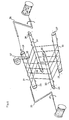
- FIG. 5 An installation suitable for the industrial manufacture of shoelace or cord according to the process described is shown diagrammatically in FIG. 5.
- motorized buckets 19 and 20 are fixed to each of the carriages 15 and 16.
- the installation described has two benches 13 and 14 because they give good results but for certain applications, one or more benches can also be envisaged.
- the cords 8 pinched in the rollers 9 and 10 are pulled from the reel by these two rollers 9 and 10 driven appropriately by a servo motor for example; the cords 8 descend by gravitation between the two lower rollers 11 and 12 which are in this phase of the cycle separated from each other, by an appropriate device such as a jack 21.
- the upper rollers 9 and 10 stop and lock in this position.
- the lower rollers 11 and 12 and upper 9 and 10 will preferably have a good coefficient of friction with respect to the cord and may for example be rubberized.
- a suitable device will exert a torque on at least one of the lower rollers, for example by means of a torque motor, so as to exert traction on the cords retained by the upper rollers 9 and 10.
- This tensioning of the cords makes it possible to tighten the cords of the cord located between the two pairs of lower and upper rollers.
- the hot air guns 17 and 18 heat and weld by an at least superficial fusion the wires successively of all the cords, according to the treatment process previously described.
- the nozzles of the hot air guns will be adapted according to the length of the treated part that is desired.
- the horizontal width of these nozzles and the speed of movement of the carriages make it possible to adjust the time of application of the cnaud air on each cord. for example tical.
- the scissors will preferably be placed at a distance from the hot air guns so that the treated parts are cut while they are cooled, so that the cut is clear.
- the lower rollers 11 and 12 move apart, for example via the jack 21; the laces, such as that shown in Figure 5 under the reference 22 fall and are collected by an appropriate packaging device.
- the cutting system could have been achieved by means of a second heat gun or a form of nozzle such that it locates longer on a portion of the cord, the jet of hot air in order to cause the fusion complete the section which would have cut the cord.
- the carts could have had a system, for example a roller soaked in varnish which would have been deposited on the cords before the passage of the hot air guns.
- the installation described is particularly suitable for mass production although it is not necessary for all the cords to be of the same type.
- the temperature of the hot air, the speed of travel from trolleys as well as the dimensions of the nozzles, the hot air guns will be adapted according to the material and the dimensions of the cords to be treated.
- the installation is designed to rewind the cord which has undergone the treatment according to the method, so that it can be cut later according to the needs of the user.
- FIG. 6 represents a coil, in the case of the figure, of substantially parallelepiped shape.
- Pulleys 23, 24, 25, 26, 27, 28, 29 and 30 are placed at the corners of the parallelepiped, slightly inside it, belts 31, 32, 33, 34 are placed between the pulleys so that they form the parallel edges of the parallelepiped, the return of the belts taking place inside the parallelepiped.
- a pin 35 wraps the cord, coming from a reel, around the parallelepiped, the turns formed resting substantially perpendicular on the belts which form the parallel edges of the parallelepiped.
- Belts 31, 32, 33 and 34 are driven in the steering, at the same speed by any suitable means such as a motor driving the pulleys.
- the turns progress on edges of the parallelepiped then using a second pin 36, the turns are unwound by the lommepip ⁇ de and rewound according to known means.
- the belts will be slightly divergent in order to gradually tension the turns during their movement on the edges of the parallelepiped formed by the moving belts.
- the running speed of the belts. the size of the nozzles and the temperature of the hot air will be adjusted according to the type of cords to be treated.
Landscapes
- Engineering & Computer Science (AREA)
- Mechanical Engineering (AREA)
- Manufacturing & Machinery (AREA)
- Textile Engineering (AREA)
- Treatment Of Fiber Materials (AREA)
- Ropes Or Cables (AREA)
- Footwear And Its Accessory, Manufacturing Method And Apparatuses (AREA)
- Braiding, Manufacturing Of Bobbin-Net Or Lace, And Manufacturing Of Nets By Knotting (AREA)
Applications Claiming Priority (2)
| Application Number | Priority Date | Filing Date | Title |
|---|---|---|---|
| FR8208527 | 1982-05-10 | ||
| FR8208527A FR2526453B1 (fr) | 1982-05-10 | 1982-05-10 | Une cordelette, son procede de traitement ainsi qu'une installation de mise en oeuvre du procede |
Publications (1)
| Publication Number | Publication Date |
|---|---|
| EP0094330A1 true EP0094330A1 (de) | 1983-11-16 |
Family
ID=9274077
Family Applications (1)
| Application Number | Title | Priority Date | Filing Date |
|---|---|---|---|
| EP83440026A Withdrawn EP0094330A1 (de) | 1982-05-10 | 1983-04-29 | Schnürband, Verfahren zu dessen Behandlung und Einrichtung zur Ausführung dieses Verfahrens |
Country Status (3)
| Country | Link |
|---|---|
| EP (1) | EP0094330A1 (de) |
| JP (1) | JPS58203191A (de) |
| FR (1) | FR2526453B1 (de) |
Cited By (4)
| Publication number | Priority date | Publication date | Assignee | Title |
|---|---|---|---|---|
| GB2337686A (en) * | 1998-05-28 | 1999-12-01 | Joseph John Orsi | Making shoe laces |
| EP3366605A1 (de) * | 2017-02-23 | 2018-08-29 | Francesco Costantino Ambrogio Gropallo | Verfahren zur herstellung eines kabelförmigen oder bandförmigen teils von taschen oder kästen |
| CN111395024A (zh) * | 2020-02-27 | 2020-07-10 | 广东溢达纺织有限公司 | 绳带包胶头辅助装置及绳带包胶头方法 |
| CN113245125A (zh) * | 2021-05-11 | 2021-08-13 | 上海锦湾实业有限公司 | 一种胶头整齐牢固的编织绳带以及生产工艺 |
Families Citing this family (5)
| Publication number | Priority date | Publication date | Assignee | Title |
|---|---|---|---|---|
| JPH07102161B2 (ja) * | 1992-02-26 | 1995-11-08 | 松浦産業株式会社 | 手提げ袋用提げ手の製造方法 |
| EP4395661B1 (de) * | 2021-09-01 | 2026-03-11 | Tovka, Davut | Schneid- und härtungsmaschine für chirurgische fäden |
| TR2021013728A1 (tr) | 2021-09-01 | 2023-03-21 | Tovka Davut | Ameli̇yat i̇pli̇ği̇ kesme ve sertleşti̇rme maki̇nesi̇ |
| CN115961494A (zh) * | 2022-11-29 | 2023-04-14 | 湖南航天机电设备与特种材料研究所 | 一种绳带束头机 |
| TWI880608B (zh) * | 2024-01-24 | 2025-04-11 | 楊富翔 | 智能數位化鞋帶束頭機 |
Citations (6)
| Publication number | Priority date | Publication date | Assignee | Title |
|---|---|---|---|---|
| DE137290C (de) * | ||||
| GB191120627A (en) * | 1911-09-18 | 1912-09-12 | Simon Willard Wardwell | Improvements in or relating to Lacings. |
| DE466642C (de) * | 1928-01-19 | 1928-10-10 | Overbeck & Co M B H H | Verfahren zur Erzeugung von Einschnuerungen in gummielastischen Schlauchgeflechten |
| FR909448A (fr) * | 1945-02-28 | 1946-05-08 | Lacet | |
| US3323165A (en) * | 1963-10-14 | 1967-06-06 | Monsanto Co | Variable denier yarn apparatus |
| FR2367591A1 (fr) * | 1976-10-12 | 1978-05-12 | Taylor Thomas & Sons Inc | Procede et appareil |
-
1982
- 1982-05-10 FR FR8208527A patent/FR2526453B1/fr not_active Expired
-
1983
- 1983-04-29 EP EP83440026A patent/EP0094330A1/de not_active Withdrawn
- 1983-05-10 JP JP58080258A patent/JPS58203191A/ja active Pending
Patent Citations (6)
| Publication number | Priority date | Publication date | Assignee | Title |
|---|---|---|---|---|
| DE137290C (de) * | ||||
| GB191120627A (en) * | 1911-09-18 | 1912-09-12 | Simon Willard Wardwell | Improvements in or relating to Lacings. |
| DE466642C (de) * | 1928-01-19 | 1928-10-10 | Overbeck & Co M B H H | Verfahren zur Erzeugung von Einschnuerungen in gummielastischen Schlauchgeflechten |
| FR909448A (fr) * | 1945-02-28 | 1946-05-08 | Lacet | |
| US3323165A (en) * | 1963-10-14 | 1967-06-06 | Monsanto Co | Variable denier yarn apparatus |
| FR2367591A1 (fr) * | 1976-10-12 | 1978-05-12 | Taylor Thomas & Sons Inc | Procede et appareil |
Cited By (5)
| Publication number | Priority date | Publication date | Assignee | Title |
|---|---|---|---|---|
| GB2337686A (en) * | 1998-05-28 | 1999-12-01 | Joseph John Orsi | Making shoe laces |
| EP3366605A1 (de) * | 2017-02-23 | 2018-08-29 | Francesco Costantino Ambrogio Gropallo | Verfahren zur herstellung eines kabelförmigen oder bandförmigen teils von taschen oder kästen |
| CN111395024A (zh) * | 2020-02-27 | 2020-07-10 | 广东溢达纺织有限公司 | 绳带包胶头辅助装置及绳带包胶头方法 |
| CN111395024B (zh) * | 2020-02-27 | 2023-08-29 | 广东康派环创科技有限公司 | 绳带包胶头辅助装置及绳带包胶头方法 |
| CN113245125A (zh) * | 2021-05-11 | 2021-08-13 | 上海锦湾实业有限公司 | 一种胶头整齐牢固的编织绳带以及生产工艺 |
Also Published As
| Publication number | Publication date |
|---|---|
| FR2526453B1 (fr) | 1985-11-15 |
| FR2526453A1 (fr) | 1983-11-10 |
| JPS58203191A (ja) | 1983-11-26 |
Similar Documents
| Publication | Publication Date | Title |
|---|---|---|
| EP0367661B1 (de) | Verfahren und Vorrichtung zur Herstellung eines aus Verstärkungsfasern und einem organischen thermoplastischen Material geformten Fadens oder Bandes | |
| CH393010A (fr) | Procédé et appareil pour la fabrication de tubes en polyamides avec gaine extérieure et tubes ainsi obtenus | |
| EP0094330A1 (de) | Schnürband, Verfahren zu dessen Behandlung und Einrichtung zur Ausführung dieses Verfahrens | |
| CA2304403A1 (fr) | Procede de fabrication d'un ruban composite forme de fibres de renforcement et de matiere organique thermoplastique | |
| FR2514297A1 (fr) | Procede pour fixer un ruban elastique tendu a une bande en matiere impermeable notamment pour la fabrication de couches | |
| FR2807966A1 (fr) | Procede et dispositif de fabrication d'un profile composite forme de matiere organique thermoplastique renforcee par des fibres de renforcement | |
| FR2508374A1 (fr) | Procede permettant de former des rainures longitudinales sur un filament en materiau thermoplastique ou a la surface d'un corps cylindrique allonge | |
| EP0640570B1 (de) | Verfahren zur Herstellung von geschnittenen Fasern und Vorrichtung dafür | |
| EP0125953B1 (de) | Verfahren zum Herstellen einer Saite aus mehreren Komponenten | |
| FR2854814A1 (fr) | Corde synthetique pour raquette de tennis | |
| FR2461466A1 (fr) | Arbre artificiel, et procede et appareil pour sa fabrication | |
| FR2547603A1 (fr) | Dispositif et procede pour raccorder les bords de deux bandes | |
| EP0063515B1 (de) | Verfahren zur Herstellung von Pflanzenstützen, Vorrichtung zur Durchführung dieses Verfahrens und erhaltene Pflanzenstützen | |
| EP0049196B1 (de) | Saiten aus Kunststoffen für Tennisschläger | |
| FR2550232A1 (fr) | Procede pour introduire une bande de matiere thermosensible dans un four | |
| EP3230513B1 (de) | Textile verstärkung für pultrusion und verfahren zur herstellung davon | |
| FR2535356A1 (fr) | Procede de revetement de cables ou analogues | |
| FR3048635B1 (fr) | Armature textile lisse pour pultrusion, procede et dispositif pour sa realisation, et son utilisation pour la fabrication de pieces par pultrusion | |
| EP4378034A1 (de) | Verfahren zum binden eines kabelbündels mittels einfacher bandbindungen | |
| BE535324A (de) | ||
| FR2552924A1 (fr) | Procede et dispositif de pose d'un revetement entourant un objet presentant un axe longitudinal, et cable obtenu par un tel procede | |
| BE720541A (de) | ||
| BE483561A (de) | ||
| FR2636357A1 (fr) | Procede et dispositif pour l'enduction de bandes de grandes longueurs en continu | |
| FR2625738A1 (fr) | Sangle de levage et son procede de fabrication |
Legal Events
| Date | Code | Title | Description |
|---|---|---|---|
| PUAI | Public reference made under article 153(3) epc to a published international application that has entered the european phase |
Free format text: ORIGINAL CODE: 0009012 |
|
| AK | Designated contracting states |
Designated state(s): AT BE CH DE GB IT LI LU NL SE |
|
| STAA | Information on the status of an ep patent application or granted ep patent |
Free format text: STATUS: THE APPLICATION IS DEEMED TO BE WITHDRAWN |
|
| 18D | Application deemed to be withdrawn |
Effective date: 19840717 |
|
| RIN1 | Information on inventor provided before grant (corrected) |
Inventor name: CROMBEZ, CHARLES LEON |