EP0094476B1 - Tränke für Geflügel - Google Patents
Tränke für Geflügel Download PDFInfo
- Publication number
- EP0094476B1 EP0094476B1 EP83101011A EP83101011A EP0094476B1 EP 0094476 B1 EP0094476 B1 EP 0094476B1 EP 83101011 A EP83101011 A EP 83101011A EP 83101011 A EP83101011 A EP 83101011A EP 0094476 B1 EP0094476 B1 EP 0094476B1
- Authority
- EP
- European Patent Office
- Prior art keywords
- bell
- support surface
- tubular member
- drinker
- cartridge
- Prior art date
- Legal status (The legal status is an assumption and is not a legal conclusion. Google has not performed a legal analysis and makes no representation as to the accuracy of the status listed.)
- Expired
Links
- 244000144977 poultry Species 0.000 title claims description 16
- XLYOFNOQVPJJNP-UHFFFAOYSA-N water Substances O XLYOFNOQVPJJNP-UHFFFAOYSA-N 0.000 claims description 10
- 239000004033 plastic Substances 0.000 claims description 5
- 229920003023 plastic Polymers 0.000 claims description 5
- 238000007789 sealing Methods 0.000 claims description 3
- 230000037431 insertion Effects 0.000 claims 1
- 238000003780 insertion Methods 0.000 claims 1
- 239000007788 liquid Substances 0.000 claims 1
- 239000000725 suspension Substances 0.000 description 7
- 230000000712 assembly Effects 0.000 description 2
- 238000000429 assembly Methods 0.000 description 2
- 230000006835 compression Effects 0.000 description 2
- 238000007906 compression Methods 0.000 description 2
- 238000002347 injection Methods 0.000 description 2
- 239000007924 injection Substances 0.000 description 2
- 239000000463 material Substances 0.000 description 2
- 239000002991 molded plastic Substances 0.000 description 2
- 238000010276 construction Methods 0.000 description 1
- 229920002457 flexible plastic Polymers 0.000 description 1
- 230000005484 gravity Effects 0.000 description 1
- 238000001746 injection moulding Methods 0.000 description 1
- 238000007689 inspection Methods 0.000 description 1
- 238000004519 manufacturing process Methods 0.000 description 1
- 238000012986 modification Methods 0.000 description 1
- 230000004048 modification Effects 0.000 description 1
- 239000004576 sand Substances 0.000 description 1
- 239000007787 solid Substances 0.000 description 1
Images

Classifications
-
- A—HUMAN NECESSITIES
- A01—AGRICULTURE; FORESTRY; ANIMAL HUSBANDRY; HUNTING; TRAPPING; FISHING
- A01K—ANIMAL HUSBANDRY; AVICULTURE; APICULTURE; PISCICULTURE; FISHING; REARING OR BREEDING ANIMALS, NOT OTHERWISE PROVIDED FOR; NEW BREEDS OF ANIMALS
- A01K39/00—Feeding or drinking appliances for poultry or other birds
- A01K39/02—Drinking appliances
- A01K39/022—Drinking appliances with weight-controlled supply
Definitions
- the invention relates to a poultry drinker according to the preamble of Claim 1.
- poultry drinkers are commercially available worldwide. These poultry drinkers conventionally include a bell including a watering trough at the bottom thereof and a neck at the top. Operatively associated with the neck a valve is provided, as well as some sort of valve actuating' structure mounted on the bell itself in the neck area. Typical of these structures are those shown in US-A-4,323,036; US-A-3,590,782; US-A-4,196,699; and US-A-4,215,653.
- US ⁇ A ⁇ 4,323,036 shows a poultry automatic apparatus having a bell with a valve means and a cartridge associated therewith.
- the bell has a central opening formed by an annular lip which is rotatably mounted in a groove so that the bell may turn relative to a sleeve.
- the poultry drinker, and component parts thereof, according to the present invention take into account the above-mentioned problems associated with the present commercial production of poultry drinkers, and provide a structure that is easy to ship, includes readily replaceable components at the prime area of breakage, and yet is simply assembled in the field, and functions at least substantially as well as presently available poultry drinkers.
- the poultry drinker of the present invention is headless. That is at the portion of the bell opposite the top no head is provided, but rather merely an opening with an annular support surface defining the opening. Without a head, the drinker can be easily shipped, taking up much less space than most conventional drinkers of the same basic size.
- connection of the drinker bell to the valve means, and to a ballast is provided by a replaceable cartridge assembly.
- the cartridge is insertable into operative engagement with the annular support surface defining the opening at the top of the bell, and it is held in place by a nut threaded into engagement with a portion of the cartridge extending out through the bell open top.
- a conventional valve assembly may be attached to the cartridge, and openings are provided in the cartridge to allow water flow from the valve down the exterior surface of the bell into the trough.
- a threaded post is provided for connection to a stand, ballast bowl, or the like. Since damage to drinkers most often occurs at the connection of the valve, valve actuating portion, or ballast or stand connection, and since the replaceable cartridge according to the invention performs all those functions, if any damage does ensue the cartridge may merely be replaced, and the entire drinker need not be discarded.
- the replaceable cartridges according to the present invention may be of several types to provide great flexibility in the type of drinker irrespective of the construction of the bell or valve assembly.
- one type of cartridge can provide for operation of the drinker solely as a suspension type drinker, such as shown in US-A-3,590,782.
- Another type of cartridge may provide for the utilization of the drinker primarily as a ground-supported drinker, such as shown in US-A-4,164,201.
- a third type cartridge may provide for utilization of the drinkers either a standing or hanging type drinker, such as shown in US-A-4,196,699.
- the bell according to the present invention is preferably dimensioned to provide for maximum stackability thereof.
- the bell is formed having a top conical portion with a large angle of taper, and a bottom conical portion with a small angle of taper.
- the taper of the bottom portion is substantial enough to provide good nestability of the drinkers.
- a headless bell with such nestability provisions allows a fantastic increase in the number of complete unassembled drinkers that may be packaged within a given volume, and can result in substantially lower transportation costs.
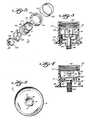
- An exemplary poultry drinker 10 includes a bell 12 (see Figures 1 and 5 in particular) with a watering trough 13 formed at the bottom thereof, and an open headless top indicated generally by reference numeral 14.
- the top includes a substantially planar annular support surface 15 defining the actual opening 16 in the drinker top.
- the opening 16 receives a cartridge assembly according to the present invention, shown generally by reference numerals 18, 18' in Figures 2 through 4.
- a portion of the annular support surface 15 defines a cutout 19 which receives a flange 20, 20' associated with the cartridge assembly 18, 18' to provide means for preventing rotation between the cartridge assembly 18, 18' and the bell 12 during use.
- the bell 12 is commonly formed of injection molded plastic.
- the bell may have a wide variety of shapes, such as those illustrated in US-A-3,590,782; US-A-4,196,699; or US-A-4,215,653.
- the bell will preferably have the shape illustrated in Figure 1, having a top portion 22 comprising the frustum of a right circular cone having a relatively large angle a and having a bottom portion 23 also comprising a frustum of a right circular cone, but having a smaller angle P.
- the angle a is not critical, but is normally about 30°.
- the angle ⁇ is approximately 7 to 9°. If P is too much smaller than 7°, the drinker does not nest properly. If it is too much larger than 9°, the drinker must be made wider than it otherwise would be, and its center of gravity is changed, and it is not as well-balanced.
- valve assembly 25 which preferably is a conventional valve assembly such as shown in US-A-4,196,699 or US-A-4,164,201.
- the valve assembly 25 conventionally includes a stem 26, a top cap 27 adapted to be connected to the source of water, and adjustor collar 28, and an interior valve member (shown in dotted line at 29 in Figure 4) cooperating with a valve seat (30 in Figure 4).
- Actuation of the valve member may be provided by an external structure engaging the valve seat 30 (as in US-A-4,196,699), or by a component extending outwardly from the stem 26 operatively associated with the valve member 29 (such as valve actuator stem 31 in Figure 4; valves of this general type are shown in U.S.
- a spring (not shown) is provided interiorly of the adjustor collar 28, and a spring compression ring 33 can move to either of two detent positions (see cutout 34 in Figure 1) to provide varying degrees of spring force application, as is known per se in commercially available poultry drinkers.
- the drinker 10 may or may not include a stand or ballast cone, such as the stand/ballast cone 37 illustrated in Figure 1.
- the stand 37 is conventional, having a pan 38 formed at the bottom, and having a hollow interior.
- a ballast material such as water, sand, or the like, can be provided in the pan 38, or can be placed inside the hollow interior, with a cap at the bottom to prevent the ballast material from falling out.
- the pan 38 may include an enlarged annular lip 39 which is slightly spaced from the interior surface 41 of the bell 12 in order to prevent too much sideways movement of the bell 12 for the situation wherein the pan 38 extends outwardly from the bottom of the bell 12 and sits on the ground.
- the lip 39 prevents too much sideways movement during this reciprocation. If the drinker 10 is to be used only as a suspension drinker, the bottom of the pan 38 need not extend outwardly from the bottom of the bell 12.
- a tube 42 which is adapted to be connected to the cartridge 18. This is preferably provided by forming interior threading in the tube 42, which cooperates with the exteriorly threaded post 44, 44' (see Figures 2 through 4) extending downwardly from the cartridge 18, 18'. While the post 44 preferably is a solid member with external threading, it also may be a tubular member with internal threading, with the receiving-component on the stand or ballast member 37 adapted accordingly.
- the cartridge 18 ( Figures 2 and 3) is utilized when it is desirable to have a drinker 10 that can be suspended or sit on the ground.
- the cartridge 18' is utilized when it is desirable that the drinker 10 be only a suspension type drinker.
- Functionally equivalent components in the Figures 3 and 4 embodiments are designated by the same reference numeral, only in the Figure 4 embodiment followed by a
- the cartridge 18 includes an annular support surface 46 which engages the underside of the bell annular support surface 15 as the flange 20 is received within cutout 19.
- a tubular body member 47 Extending upwardly from the annular support surface 46 is a tubular body member 47.
- the tubular body member 47 includes a valve actuating component formed therewith. In the illustrative embodiment illustrated in the drawing, this comprises the horizontally extending interior shelf 48, which is integral with the body 47.
- the shelf 48 may have a central interiorly upwardly projecting pin (not shown) to actuate the valve.
- Means are provided defining a plurality of water-passing openings 49 in the tubular body member 47, just above the shelf 48. Preferably four such openings 49 are provided.
- Means are also provided for releasably holding the cartridge assembly so that the support surface 46 is in contact with the bell support surface 15.
- Such means comprise exterior threading 51 on the surface of the tube 47 just above the support surface 46, and below the openings 49; and a plastic nut 52 having interior threadings 53 cooperating with the exterior threading 51. The nut 52 engages the top of the bell annular support surface 15, clamping support surface 15 between it and the cartridge annular support surface 46.
- Means are also provided for releasably attaching the valve means 25 to the cartridge tubular member 47. This is preferably provided by interior threading 55 adjacent the open top of the cartridge 47, which interior threading cooperates with an exteriorly threaded-tubular portion of the valve means adjustor collar 28 (see patent 4,196,699).
- the threaded post 44 is mounted for slight linear movement along the axis of the tubular member 47 with respect to the shelf 48.
- This may be accomplished by providing the flexible sealing cup 58, which is made of flexible plastic, rubber, or the like.
- the flexible cup may be attached at one end 59 thereof between the ring 60, which depend downwardly from shelf 48 and is integral therewith and the interior surface of the tubular member 47.
- Such securement can be facilitated by providing an ultrasonic weld or the like.
- the cup is attached to the post 44, above the threads. Again this attachment may be facilitated by an ultrasonic weld.
- a plurality of pins 64 which pass through openings (not shown) in shelf 48, which openings are slightly larger than the diameter of the pins 64.
- the pins 64 extend upwardly from, and are integral with, the disc 66 formed at the end of post 44 oppostie the threading. Due to the flexibility of the cup member 58, the pins 64 may move linearly with respect to the shelf 48, parallel to the axis of the tubular member 47. The cup 58 also prevents any water which may pass through the openings receiving the pins 64 from going into the interior of the bell 12.
- the cup 58 and pins 64 are not necessary.
- a disc 66' is formed on the end of the post 44' opposite the threads, this disc 66' having substantially the same outside diameter as the inside diameter of ring 60'.
- the disc 66' is received within the ring 60', and may be ultrasonically welded thereto. In this embodiment, no holes are formed in the shelf 48'.
- an antisplash ring 68 which is merely a plastic tube having an inside diameter slightly greater than the outside diameter of the tubular member 47, 47', and having a length approximately the distance between the nut 52 and adjustor collar 28 when the drinker 10 is assembled (see Figure 1). Cutouts 69 are formed in the bottom portion of the ring 68 (e.g. three cutouts 69 are provided when four openings 49, 49' are provided). Water passing out of openings 49, 49' will then impact the interior of the antisplash ring 68, and trickle down and flow out of the cutouts 69 down the exterior surface of the bell 12.
- the bell 12, stand 37, and cartridge tubular member 47,47' are formed from injection molded plastic. If the cartridge assembly is to become a hanging/standing cartridge assembly 18, holes are drilled in the shelf 48, pins 64 of the post 44 are passed through these holes, ring 65 is ultrasonically welded in place, and the flexibility of cup member 58 secures it between the ring 60 and the interior surface of tubular member 47, and to post 44. If the cartridge assembly is to become a suspension-only cartridge assembly 18', the disc 66 of post 44' is ultrasonically welded to ring 60.
- the four openings 49, 49' are formed therein by merely passing two drill bits through the wall of tubular member 47, 47', each drill bit forming two of the openings 49, 49'.
- the bells 12 are stacked (nested) for shipment, and because they are headless and are contoured particularly for nesting, they can be shipped to the field in a minimum size shipping container (or a maximum number of bells may be provided in a particular size shipping container).
- the stands 37 likewise are nested and shipped to the field in that manner, while the cartridge assemblies 18, 18' and the valve assemblies 25 are provided loosely, or in plastic bags, within the shipping container and the volume not taken up by bells 12 or stands 37.
- the drinkers 10 When they arrive in the field, the drinkers 10 are assembled. This is easily accomplished first by unthreading nut 52 from threads 51 of the cartridge assembly 18, and passing the cartridge assembly up through the openings 16 in the top of bell 12 from the interior of the bell until the flange 20 is received by cutout 19, and cartridge support surface 46 engages the underside of the bell annular support surface 15. Then nut 52 is threaded into engagement with threads 51, to clamp the cartridge 18 in place. Should any damage occur to the cartridge components, a new cartridge can easily be inserted in its place, and there is no necessity to discard the entire bell 12.
- the tubular interiorly threaded top portion 42 thereof is then inserted into the interior of the bell 12, and moved into engagement with the threads on post 44, and threaded into engagement therewith.
- the stand 37 can be connected to the cartridge 18 before the cartridge is inserted into place with respect to the ball 12.
- the antisplash ring 68 if utilized, is loosely placed over the exterior of the tube 47 above nut 52, and covering openings 49, and then the adjustor collar 28 of the valve assembly 25 is screwed into engagement with the threads 55 of the cartridge tubular member 47.
- the valve 27 is connected to a water source in the conventional manner, and the drinker 10 is ready for operation, the adjustment component 33 of the valve assembly 25 being placed in the lower position if the drinker is to be operated as a standing drinker, and in the upper position if it is to be a suspension drinker, thereby varying the compression of the srping between the adjustor collar 28 and stem 26.
- the drinker then operates in the manner described in US-A-4,196,699.
Landscapes
- Life Sciences & Earth Sciences (AREA)
- Environmental Sciences (AREA)
- Birds (AREA)
- Animal Husbandry (AREA)
- Biodiversity & Conservation Biology (AREA)
- Feeding And Watering For Cattle Raising And Animal Husbandry (AREA)
Claims (11)
Applications Claiming Priority (4)
| Application Number | Priority Date | Filing Date | Title |
|---|---|---|---|
| US37849182A | 1982-05-14 | 1982-05-14 | |
| US378491 | 1982-05-14 | ||
| US390774 | 1982-06-21 | ||
| US06/390,774 US4452179A (en) | 1982-05-14 | 1982-06-21 | Advanced poultry drinker construction |
Publications (2)
| Publication Number | Publication Date |
|---|---|
| EP0094476A1 EP0094476A1 (de) | 1983-11-23 |
| EP0094476B1 true EP0094476B1 (de) | 1986-07-30 |
Family
ID=27008248
Family Applications (1)
| Application Number | Title | Priority Date | Filing Date |
|---|---|---|---|
| EP83101011A Expired EP0094476B1 (de) | 1982-05-14 | 1983-02-03 | Tränke für Geflügel |
Country Status (3)
| Country | Link |
|---|---|
| US (1) | US4452179A (de) |
| EP (1) | EP0094476B1 (de) |
| DE (2) | DE8219720U1 (de) |
Families Citing this family (4)
| Publication number | Priority date | Publication date | Assignee | Title |
|---|---|---|---|---|
| US4452179A (en) * | 1982-05-14 | 1984-06-05 | Monoflo International, Inc. | Advanced poultry drinker construction |
| US4770126A (en) * | 1986-01-21 | 1988-09-13 | Ziggity Systems, Inc. | Mini drinker |
| US4793291A (en) * | 1986-01-21 | 1988-12-27 | Ziggity Systems, Inc. | Mini drinker |
| CN110402848B (zh) * | 2019-06-24 | 2022-03-22 | 湖南欣牧达畜牧设备有限公司 | 一种家禽养殖用移动式喂水装置 |
Family Cites Families (11)
| Publication number | Priority date | Publication date | Assignee | Title |
|---|---|---|---|---|
| US2632463A (en) * | 1949-07-20 | 1953-03-24 | Shenandoah Equipment Company | Automatic poultry fountain |
| DE1059704B (de) * | 1958-07-21 | 1959-06-18 | Rudolf Kreyer | Gefluegeltraenke |
| GB1197007A (en) * | 1968-05-15 | 1970-07-01 | Plasson Maagan Michael Ind Ltd | Suspension Type Poultry Drinking Fountain |
| GB1238381A (de) * | 1969-06-19 | 1971-07-07 | ||
| US3861358A (en) * | 1973-10-25 | 1975-01-21 | James P Bowell | Animal watering device |
| US4164201A (en) * | 1977-10-17 | 1979-08-14 | Interfarm Corporation | Ground-supported poultry drinking fountain |
| GB1559746A (en) * | 1978-01-13 | 1980-01-23 | Leeming D C | Poultry drinking troughs |
| IT1092124B (it) * | 1978-01-18 | 1985-07-06 | Pirovano Camillo | Abbeveratoio per polli e simili animali atto ad essere sospeso o appoggiato per terra |
| US4180015A (en) * | 1978-03-23 | 1979-12-25 | Dawson Carl B Jr | Fail safe suspension poultry drinker |
| US4323036A (en) * | 1980-04-22 | 1982-04-06 | Michael Salerno | Automatic watering apparatus |
| US4452179A (en) * | 1982-05-14 | 1984-06-05 | Monoflo International, Inc. | Advanced poultry drinker construction |
-
1982
- 1982-06-21 US US06/390,774 patent/US4452179A/en not_active Expired - Fee Related
- 1982-07-09 DE DE19828219720U patent/DE8219720U1/de not_active Expired
-
1983
- 1983-02-03 EP EP83101011A patent/EP0094476B1/de not_active Expired
- 1983-02-03 DE DE8383101011T patent/DE3364805D1/de not_active Expired
Also Published As
| Publication number | Publication date |
|---|---|
| DE3364805D1 (en) | 1986-09-04 |
| US4452179A (en) | 1984-06-05 |
| EP0094476A1 (de) | 1983-11-23 |
| DE8219720U1 (de) | 1982-12-16 |
Similar Documents
| Publication | Publication Date | Title |
|---|---|---|
| CA2435024C (en) | Bird feeder | |
| US5353964A (en) | Twin-bottle nursing bottle | |
| US3868926A (en) | Automatic water dispenser | |
| US6557297B2 (en) | Adjustable water plant container support assembly | |
| US4869390A (en) | Spill proof cup | |
| EP0151862A2 (de) | Saugflasche für Babys | |
| US2591126A (en) | Bird feeder | |
| US5655477A (en) | Bird feeder | |
| US4269143A (en) | Teat cup assembly | |
| US5671696A (en) | Molded bird feeder assembly | |
| EP0094476B1 (de) | Tränke für Geflügel | |
| US5819980A (en) | Gurgle and slosh free canteen | |
| GB2268869A (en) | Bird feeder. | |
| US6705592B2 (en) | Closure for a container to be pressurized, as well as such a container | |
| US8136466B2 (en) | Self-bailing watercraft valve | |
| EP1297814B1 (de) | Sauger für Kleinkinder für dicke Nahrung | |
| US10899508B1 (en) | Overmolded tricuspid valve for a container | |
| GB2134765A (en) | Animal drinkers | |
| US20060185602A1 (en) | Bird feeder accessory | |
| US20230380380A1 (en) | Universal drinker base | |
| US5791061A (en) | Marking plumb bob | |
| US11980588B2 (en) | Baby feeding bottle | |
| GB2287632A (en) | Self-acting plant watering device | |
| WO2004032611A1 (en) | Liquid storage tank and water feeder for rearing animal using it | |
| GB2223153A (en) | Animal drinkers |
Legal Events
| Date | Code | Title | Description |
|---|---|---|---|
| PUAI | Public reference made under article 153(3) epc to a published international application that has entered the european phase |
Free format text: ORIGINAL CODE: 0009012 |
|
| AK | Designated contracting states |
Designated state(s): DE FR GB IT NL |
|
| TCNL | Nl: translation of patent claims filed | ||
| 17P | Request for examination filed |
Effective date: 19831110 |
|
| RAP1 | Party data changed (applicant data changed or rights of an application transferred) |
Owner name: MONOFLO INTERNATIONAL, INC. |
|
| RIN1 | Information on inventor provided before grant (corrected) |
Inventor name: RADER, HELMUT |
|
| GRAA | (expected) grant |
Free format text: ORIGINAL CODE: 0009210 |
|
| AK | Designated contracting states |
Kind code of ref document: B1 Designated state(s): DE FR GB IT NL |
|
| PG25 | Lapsed in a contracting state [announced via postgrant information from national office to epo] |
Ref country code: NL Effective date: 19860730 Ref country code: IT Free format text: LAPSE BECAUSE OF FAILURE TO SUBMIT A TRANSLATION OF THE DESCRIPTION OR TO PAY THE FEE WITHIN THE PRESCRIBED TIME-LIMIT;WARNING: LAPSES OF ITALIAN PATENTS WITH EFFECTIVE DATE BEFORE 2007 MAY HAVE OCCURRED AT ANY TIME BEFORE 2007. THE CORRECT EFFECTIVE DATE MAY BE DIFFERENT FROM THE ONE RECORDED. Effective date: 19860730 |
|
| REF | Corresponds to: |
Ref document number: 3364805 Country of ref document: DE Date of ref document: 19860904 |
|
| EN | Fr: translation not filed | ||
| NLV1 | Nl: lapsed or annulled due to failure to fulfill the requirements of art. 29p and 29m of the patents act | ||
| PLBE | No opposition filed within time limit |
Free format text: ORIGINAL CODE: 0009261 |
|
| STAA | Information on the status of an ep patent application or granted ep patent |
Free format text: STATUS: NO OPPOSITION FILED WITHIN TIME LIMIT |
|
| 26N | No opposition filed | ||
| PGFP | Annual fee paid to national office [announced via postgrant information from national office to epo] |
Ref country code: FR Payment date: 19900210 Year of fee payment: 8 |
|
| ITTA | It: last paid annual fee | ||
| PGFP | Annual fee paid to national office [announced via postgrant information from national office to epo] |
Ref country code: GB Payment date: 19920203 Year of fee payment: 10 |
|
| PGFP | Annual fee paid to national office [announced via postgrant information from national office to epo] |
Ref country code: DE Payment date: 19920228 Year of fee payment: 10 |
|
| PG25 | Lapsed in a contracting state [announced via postgrant information from national office to epo] |
Ref country code: GB Effective date: 19930203 |
|
| GBPC | Gb: european patent ceased through non-payment of renewal fee |
Effective date: 19930203 |
|
| PG25 | Lapsed in a contracting state [announced via postgrant information from national office to epo] |
Ref country code: DE Effective date: 19931103 |
|
| PG25 | Lapsed in a contracting state [announced via postgrant information from national office to epo] |
Ref country code: FR Free format text: LAPSE BECAUSE OF NON-PAYMENT OF DUE FEES Effective date: 19910228 |