EP0094489A2 - Clou d'os pour le traitement des fractures dans la partie proximale du fémur et outillage adapté - Google Patents
Clou d'os pour le traitement des fractures dans la partie proximale du fémur et outillage adapté Download PDFInfo
- Publication number
- EP0094489A2 EP0094489A2 EP83102694A EP83102694A EP0094489A2 EP 0094489 A2 EP0094489 A2 EP 0094489A2 EP 83102694 A EP83102694 A EP 83102694A EP 83102694 A EP83102694 A EP 83102694A EP 0094489 A2 EP0094489 A2 EP 0094489A2
- Authority
- EP
- European Patent Office
- Prior art keywords
- section
- nail
- cross
- bone
- recess
- Prior art date
- Legal status (The legal status is an assumption and is not a legal conclusion. Google has not performed a legal analysis and makes no representation as to the accuracy of the status listed.)
- Granted
Links
Images

Classifications
-
- A—HUMAN NECESSITIES
- A61—MEDICAL OR VETERINARY SCIENCE; HYGIENE
- A61B—DIAGNOSIS; SURGERY; IDENTIFICATION
- A61B17/00—Surgical instruments, devices or methods
- A61B17/56—Surgical instruments or methods for treatment of bones or joints; Devices specially adapted therefor
- A61B17/58—Surgical instruments or methods for treatment of bones or joints; Devices specially adapted therefor for osteosynthesis, e.g. bone plates, screws or setting implements
- A61B17/68—Internal fixation devices, including fasteners and spinal fixators, even if a part thereof projects from the skin
- A61B17/72—Intramedullary devices, e.g. pins or nails
- A61B17/7208—Flexible pins, e.g. ENDER pins
-
- A—HUMAN NECESSITIES
- A61—MEDICAL OR VETERINARY SCIENCE; HYGIENE
- A61B—DIAGNOSIS; SURGERY; IDENTIFICATION
- A61B17/00—Surgical instruments, devices or methods
- A61B17/56—Surgical instruments or methods for treatment of bones or joints; Devices specially adapted therefor
- A61B17/58—Surgical instruments or methods for treatment of bones or joints; Devices specially adapted therefor for osteosynthesis, e.g. bone plates, screws or setting implements
- A61B17/88—Osteosynthesis instruments; Methods or means for implanting or extracting internal or external fixation devices
- A61B17/92—Impactors or extractors, e.g. for removing intramedullary devices
- A61B17/921—Impactors or extractors, e.g. for removing intramedullary devices for intramedullary devices
Definitions
- the invention relates to a bone nail for the treatment of fractures in the proximal thigh region, with a distal end section lying on the outside of the femoral condyle, which has a coupling section for engagement with an impact tool, an arcuately curved section between the ends and one in the proximal femur fitting proximal end section.
- Such a nail is known (DE-PS 23 41 439 or DE-GM 7 218 224). It is usually used together with several (bundle nailing).
- the individual metal bone nails are provided with a diameter that they are made of are sufficiently elastic so that they can be driven into the femoral bone canal via a window in the condyle of the femur.
- the proximal end of the nail finds its way in the bone canal and reaches the femoral head via the femoral neck.
- the distal end of the nail is designed so that it can be brought into engagement with a driving tool. With the aid of the driving tool, the bone nail is advanced under observation on an image intensifier in the bone channel, the first nail in particular having to be rotated more or less to reduce the bone fragment.
- the force application of the driving tool at the distal end of the nail must therefore also be able to transmit considerable torques to the nail.
- the known bone nails have some disadvantages.
- the flattenings at the distal end which are oriented transversely to the plane of curvature and which are also provided with a hole for the effective attack of an impact tool, can act like chisels if they are not completely flat on the bone or parallel to it.
- the relatively sharp edges formed in this way can have an irritating effect on the neighboring tissue. Since the flattening is normally formed by an upsetting process, additional processing is necessary to remove burrs or sharp edges.
- the flattening of a round nail cross section also creates a critical transition area with a relatively high notch effect, so that there is plastic deformation or even shearing in this area at high torques at the distal end can come. If the distal ends are rotated relative to one another, several flattened distal ends require a relatively large amount of space, which can impair the patient's condition.
- the invention is therefore based on the object of creating a bone nail for the treatment of fractures in the proximal thigh area, with which it is ensured that unwanted bone injuries do not occur in the area of the proximal femur.
- the proximal end portion has a rounded thickening at the free end. If such a thickening undoubtedly increases the driving force for the individual nail, on the other hand, this can easily be accepted, because the measure according to the invention avoids that the proximal end of the nail is threaded into the neck or head area of the femur the femur in this area is injured by penetrating or penetrating into the cortical bone. The . Greater driving force in relation to that which is required for a tip at the proximal end is nevertheless in a range which is readily acceptable for such bone nails in the surgical technique used hitherto.
- the thickening is evenly rounded to avoid injury.
- the thickening is shaped like a bead. It is preferably formed by upsetting the proximal nail end.
- the plane of curvature of the bone nail lies approximately in the plane that is spanned between the femoral shaft and the femoral neck.
- the force is introduced into the implanted nail essentially parallel to the femoral shaft and thus to the proximal end of the nails, as a result of which a torque is exerted on the curved proximal end section in the plane of curvature.
- a further embodiment of the invention provides that a flattening is provided at the free end of the thickening, the plane of which is at an angle runs to the axis of the proximal nail end so that it is approximately perpendicular to the direction of loading. This means that the flattening, the area of which can reach a considerable dimension relative to the nail cross-section, is approximately perpendicular to the femoral axis and thus also perpendicular to the direction of loading.
- the known bone nails are circular in cross section.
- the nail diameter in the plane of curvature is largely decisive for the section modulus required by the bone nails. This means that the nail can be reduced perpendicular to the plane of curvature without significantly influencing the section modulus.
- an embodiment of the invention provides that the cross section of the nail is polygonal along its length with rounded edges.
- the main axis is preferably in the plane of curvature .
- the cross section be triangular, preferably an equilateral triangle.
- This cross-sectional shape also saves material without significantly reducing the section modulus compared to a nail with a comparable circular cross-section. Since the edges of the triangular cross-section are noticeably rounded, there is no risk of injury in the bone canal. It is also without further ensures that the nail can be rotated for reduction and driving purposes.
- a triangular cross-section has the further advantage that a narrower packing is possible than with a circular cross-section, so that, if necessary, more nails can be driven in than bone nails which are circular in cross-section. For a given cross-section of the bone canal, it can be set higher than with the round nails.
- Another embodiment of the invention provides that the cross section is rectangular and the major axis lies in the plane of curvature. With such a cross-sectional shape, the material saving is even greater.
- a space-saving arrangement of the distal nail ends results if the radial extension of the distal end does not extend beyond that of the rest of the nail, i.e. the outer contour of the nail does not enlarge in the distal end area.
- an embodiment of the invention provides that a bore is provided at the distal end, preferably a through bore, the axis of which preferably lies in the plane of curvature.
- a portion of the drive tool can be engaged with the bore to allow torsion to be applied to the distal nail end.
- a recess is formed at a distance from the distal end to form a clamping section that is polygonal in cross section.
- a recess would not be necessary with regard to the application of a torque.
- a recess has the advantage that effective pull-out forces can also be applied to the nail.
- the three bone nails implanted in a femur 10 in FIG. 1 are generally designated 11. Starting from the proximal end section, they are provided with a continuous curvature, as shown at 12. A bend 13 is formed in the region of the distal end, followed by a straight piece 14.
- the bone nails 11 are driven in via a window 15 of the medial condyle of the femur 10 shown, with the aid of a driving tool, not shown, one bone nail after the other.
- the first nail driven in is normally used to reposition the fracture segment.
- the bone nails are inserted under control with the aid of an image intensifier, so that fanning out can be achieved in the head area of the femur, as a result of which a certain rotational stability of the head relative to the rest of the femur is achieved.
- the proximal end portions are provided with thickenings, which are generally designated 16 in FIG. 1.
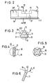
- the cross section of the nails 12 is an equilateral triangle, the corner edges of which, as shown at 17, are strongly rounded.
- One side 18 forms the convex Side of the curvature 12, while the opposite edge 19 is on the concave side of the nail 11.
- the nail 11 results in a considerable saving in material compared to a nail with the circular cross section 20, without the section modulus in the plane of curvature being significantly lower.
- the cross-sectional shape shown in Fig. 3 also has the advantage that the nails can be "packed" better in the bone canal.
- a recess 21 is formed in the straight distal end section 14, the bottom 22 of which extends approximately parallel to the side 18 of the nail 11.
- An impact tool can be brought into engagement with the recess 21 in order to advance the nail in the bone canal or to extract it from the bone canal and additionally perform a rotary movement during these movements.
- the remaining cross section 23 is easily sufficient to withstand torsional forces. It is advisable to select the transition from cross section 23 to the triangular full cross section in order to avoid unnecessarily high notch forces.
- FIG. 4 shows a cross section of a bone nail 30 which is approximately rectangular with edges 31 which are also very rounded.
- the plane of curvature coincides with the large axis 32 of the rectangular cross section.
- the bone nail 30 has a section modulus comparable to that of a circular cross-section bone nail, as indicated by the dashed circle 33. The former therefore results in considerable material savings without reducing the load-bearing capacity.
- FIG. 5 shows a nail 35, which in cross section has approximately the shape of a Maltese cross, the edges again being strongly rounded, as shown at 36.
- a dashed circle 37 shows a circular cross section of a bone nail, the section modulus of which is comparable to that of the bone nail 35.
- FIG. 6 shows the bone nail 11 with the proximal end section.
- a bead 16 with an enlarged diameter, the outer contour of which is approximately circular. Furthermore, the bead is flattened at the free end, as shown at 40.
- the flattening lies in a plane that is approximately perpendicular to the direction of loading, 'which is indicated by an arrow 41. This arrow 41 is also shown in FIG. 1.
- section 23 can additionally be provided with a bore or a through bore 23 'in order to improve the force application with an impact tool.
- a through-hole at the distal end can also be formed with any cross-section in order to attack the impact and extraction tool.
- a bore is indicated, which is arranged outside the recessed portion 21 facing the end.
- 23 '' 'in Fig. 3 is a bore arranged transversely thereto.
- the nail also has a straight section at the distal end section, which is connected to the rest of the nail by a large arch.
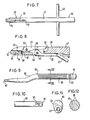
- FIGS. 1 to 6 a suggestion device for bone nails shown in FIGS. 1 to 6 is shown. It consists of a grip section 45 and a coupling section 46. Both have an elongated shaft 47 with a circular cross section, which has a cross bar 48 in the grip section 45, which is guided through a corresponding bore.
- a clutch lever 49 is in the clutch section 46 pivotally mounted (Fig. 8), with the aid of a bearing pin 50. To accommodate the clutch lever 49, a slot 51 is formed axially in the shaft 47, which receives the relatively narrow clutch lever 49, so that it is only a little over the outer contour of the Shaft 47 protrudes.
- the coupling lever 49 extends to the end of the shaft 47 and spans a recess 52 with a triangular cross section, which is open at the end of the shaft 47 and which is delimited at the opposite end by a stop wall 53, at the foot of which there is a transverse groove 54.
- a pin 55 embedded in the shaft 47 projects upward into the recess 52.
- the slot 51 In the bottom of the slot 51 there is a blind bore 56 which receives a compression spring 57 which acts on the clutch lever 49 in the clockwise direction.
- the slot 51 is provided in the diametrical direction with an opening 58 for receiving a cam 59 of a clamping lever 60.
- the clamping lever 60 is pivotally mounted in the region of the cam 59 with the aid of a bearing pin 61, the levers 49 and 60 being pivotable approximately in the same plane.
- a central portion of the lever 60 is partially received in a recess 62 of the shaft 47.
- a handle 63 extends obliquely outwards.
- the distal end of a bone nail can be inserted into the recess 42, the pin 55 engaging, for example, in the recess 21 of a bone nail according to FIGS. 1 to 3.
- a bone nail picked up in this way can now be hammered in with the help of the suggestion tool according to FIGS. 7 and 8 and manipulated in the desired manner, for example also pulled out completely or partially. An unintentional detachment of the device from the bone nail is avoided by the described clamping device.
- the reference device has an elongated shaft 65 of approximately circular cross section, which is slightly cranked in the area of the front third at 66.
- the shaft 66 tapers continuously towards the front end.
- the actual grip section has a longitudinal corrugation 68 so that the reference device can be better grasped by hand.
- An outwardly open transverse slot 69 is formed in the rear region in the shaft 65.
- a through bore 70 is also provided in parallel therewith (FIG. 10).
- the slot 69 has a width or the through-hole 70 has a diameter which is somewhat larger than the largest diameter of the bone nail.
- the device of FIGS. 9 to 12 can therefore also as suction.
- Cabinet irons are used, with the help of which it is possible to deform the bone nail in a limited way, ie to give a different curvature or direction, for example. Preferably two such devices are used.
- the tip of the lookup device can have a milling or flattening on the underside, so that it can engage in the groove 21 of the nail 11 for deflection purposes. In this way, the implanted nail can be knocked out until the suggested device can be used.
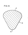
- the profile of the nail 80 according to FIG. 13 is also basically triangular like that according to FIGS. 1 to 3.
- the convex side 81 is not straight, but spherical in cross section.
- the relatively large radius of the side 81 results in a smooth transition to the radii at the edges of the nail 80.
- the concave edge 82 is also provided with a radius.
Landscapes
- Health & Medical Sciences (AREA)
- Orthopedic Medicine & Surgery (AREA)
- Life Sciences & Earth Sciences (AREA)
- Surgery (AREA)
- Medical Informatics (AREA)
- Engineering & Computer Science (AREA)
- Biomedical Technology (AREA)
- Heart & Thoracic Surgery (AREA)
- Nuclear Medicine, Radiotherapy & Molecular Imaging (AREA)
- Molecular Biology (AREA)
- Animal Behavior & Ethology (AREA)
- General Health & Medical Sciences (AREA)
- Public Health (AREA)
- Veterinary Medicine (AREA)
- Neurology (AREA)
- Surgical Instruments (AREA)
Priority Applications (1)
| Application Number | Priority Date | Filing Date | Title |
|---|---|---|---|
| AT83102694T ATE29658T1 (de) | 1982-05-18 | 1983-03-18 | Knochennagel zur versorgung von frakturen im proximalen oberschenkelbereich und zugehoeriges instrumentarium. |
Applications Claiming Priority (2)
| Application Number | Priority Date | Filing Date | Title |
|---|---|---|---|
| DE8214493U | 1982-05-18 | ||
| DE8214493 | 1982-05-18 |
Publications (3)
| Publication Number | Publication Date |
|---|---|
| EP0094489A2 true EP0094489A2 (fr) | 1983-11-23 |
| EP0094489A3 EP0094489A3 (en) | 1984-11-07 |
| EP0094489B1 EP0094489B1 (fr) | 1987-09-16 |
Family
ID=6740247
Family Applications (1)
| Application Number | Title | Priority Date | Filing Date |
|---|---|---|---|
| EP83102694A Expired EP0094489B1 (fr) | 1982-05-18 | 1983-03-18 | Clou d'os pour le traitement des fractures dans la partie proximale du fémur et outillage adapté |
Country Status (5)
| Country | Link |
|---|---|
| US (2) | US4630601A (fr) |
| EP (1) | EP0094489B1 (fr) |
| AT (1) | ATE29658T1 (fr) |
| DE (2) | DE8214493U1 (fr) |
| ES (1) | ES271476Y (fr) |
Cited By (10)
| Publication number | Priority date | Publication date | Assignee | Title |
|---|---|---|---|---|
| US4895571A (en) * | 1988-08-31 | 1990-01-23 | S+G Implants Gmbh | Stem for tibia part of a knee joint endoprosthesis |
| FR2653322A1 (fr) * | 1989-10-25 | 1991-04-26 | Ender Hans | Instrument pour la reduction et la contention des fractures trochanteriennes et insert destine a un tel instrument. |
| EP0425472A1 (fr) * | 1989-10-25 | 1991-05-02 | Hans Georg Dr. Ender | Broche pour os et outil correspondant |
| FR2656212A1 (fr) * | 1989-12-27 | 1991-06-28 | Hardy Jeanmarie | Systeme d'enclouage centro-medullaire pour immobiliser une fracture d'un os. |
| FR2657005A1 (fr) * | 1990-01-15 | 1991-07-19 | Hardy Jean Marie | Systeme d'enclouage pour le traitement des fractures notamment du type cervico-trochanteriennes et pertrochanteriennes. |
| EP0441256A1 (fr) * | 1990-02-08 | 1991-08-14 | Gebrüder Martin GmbH & Co. KG | Agencement d'outillage pour clous d'anclage aux os |
| EP0447824A1 (fr) * | 1990-03-20 | 1991-09-25 | Synthes AG, Chur | Clou intramedullaire à sections conformeés |
| EP0517435A1 (fr) * | 1991-06-01 | 1992-12-09 | Orthopaedic Research Limited Halifax | Dispositif intramédullaire pour l'ostéosynthèse |
| FR2756726A1 (fr) * | 1996-12-11 | 1998-06-12 | Khenifar Brahim | Broche cannelee degradee a pointe boutonnee |
| FR2758075A1 (fr) * | 1997-01-08 | 1998-07-10 | Brahim Khenifar | Broche souple cannelee a extremite boutonnee |
Families Citing this family (70)
| Publication number | Priority date | Publication date | Assignee | Title |
|---|---|---|---|---|
| RO89820B1 (ro) * | 1985-11-05 | 2002-06-28 | îNTREPRINDEREA INDUSTRIA TEHNICO MEDICALA | Implanturi elastice, pentru osteosinteza elastica stabila, a fracturilor femurului si, respectiv, tibiei, precum si instrumentar de lucru |
| FR2649312A1 (fr) * | 1989-07-10 | 1991-01-11 | Lacaffiniere Jean Yves | Dispositif de verrouillage superieur des broches centro-medullaires utilisees pour l'osteosynthese des fractures du femur, du tibia et de l'humerus |
| US5133759A (en) * | 1991-05-24 | 1992-07-28 | Turner Richard H | Asymmetrical femoral condye total knee arthroplasty prosthesis |
| US6712073B2 (en) * | 1995-06-26 | 2004-03-30 | Easton L. Manderson | Extramedullary rod implant for long bones |
| US5672178A (en) * | 1996-01-05 | 1997-09-30 | Petersen; Thomas D. | Fixation pin |
| US6074392A (en) * | 1998-09-01 | 2000-06-13 | Durham; Alfred A. | Method and devices for use in bone fixation procedures |
| US7008425B2 (en) | 1999-05-27 | 2006-03-07 | Jonathan Phillips | Pediatric intramedullary nail and method |
| US6706046B2 (en) * | 2000-02-01 | 2004-03-16 | Hand Innovations, Inc. | Intramedullary fixation device for metaphyseal long bone fractures and methods of using the same |
| US20040153073A1 (en) | 2000-02-01 | 2004-08-05 | Hand Innovations, Inc. | Orthopedic fixation system including plate element with threaded holes having divergent axes |
| US7857838B2 (en) | 2003-03-27 | 2010-12-28 | Depuy Products, Inc. | Anatomical distal radius fracture fixation plate |
| US7695502B2 (en) | 2000-02-01 | 2010-04-13 | Depuy Products, Inc. | Bone stabilization system including plate having fixed-angle holes together with unidirectional locking screws and surgeon-directed locking screws |
| US6767351B2 (en) | 2000-02-01 | 2004-07-27 | Hand Innovations, Inc. | Fixation system with multidirectional stabilization pegs |
| US6527775B1 (en) | 2000-09-22 | 2003-03-04 | Piper Medical, Inc. | Intramedullary interlocking fixation device for the distal radius |
| US6660009B1 (en) * | 2002-05-15 | 2003-12-09 | Carlos A. Azar | Fracture fixation system |
| US7780664B2 (en) | 2002-12-10 | 2010-08-24 | Depuy Products, Inc. | Endosteal nail |
| JP4559424B2 (ja) | 2003-08-13 | 2010-10-06 | シンセス ゲーエムベーハー | 大腿骨中へのガイドワイヤの取付のための湾曲した位置決めおよび導入機器 |
| US7635365B2 (en) | 2003-08-28 | 2009-12-22 | Ellis Thomas J | Bone plates |
| US8979846B2 (en) | 2004-04-12 | 2015-03-17 | Navin N Thakkar | Flexible nail assembly for fractures of long bones |
| US20060015101A1 (en) | 2004-07-15 | 2006-01-19 | Wright Medical Technology, Inc. | Intramedullary fixation assembly and devices and methods for installing the same |
| US7588577B2 (en) | 2004-07-15 | 2009-09-15 | Wright Medical Technology, Inc. | Guide assembly for intramedullary fixation and method of using the same |
| US20180228621A1 (en) * | 2004-08-09 | 2018-08-16 | Mark A. Reiley | Apparatus, systems, and methods for the fixation or fusion of bone |
| US8425570B2 (en) | 2004-08-09 | 2013-04-23 | Si-Bone Inc. | Apparatus, systems, and methods for achieving anterior lumbar interbody fusion |
| US20070156241A1 (en) | 2004-08-09 | 2007-07-05 | Reiley Mark A | Systems and methods for the fixation or fusion of bone |
| US8444693B2 (en) | 2004-08-09 | 2013-05-21 | Si-Bone Inc. | Apparatus, systems, and methods for achieving lumbar facet fusion |
| US9949843B2 (en) | 2004-08-09 | 2018-04-24 | Si-Bone Inc. | Apparatus, systems, and methods for the fixation or fusion of bone |
| US8470004B2 (en) * | 2004-08-09 | 2013-06-25 | Si-Bone Inc. | Apparatus, systems, and methods for stabilizing a spondylolisthesis |
| US20060036251A1 (en) | 2004-08-09 | 2006-02-16 | Reiley Mark A | Systems and methods for the fixation or fusion of bone |
| US8414648B2 (en) | 2004-08-09 | 2013-04-09 | Si-Bone Inc. | Apparatus, systems, and methods for achieving trans-iliac lumbar fusion |
| US8986348B2 (en) | 2004-08-09 | 2015-03-24 | Si-Bone Inc. | Systems and methods for the fusion of the sacral-iliac joint |
| US9662158B2 (en) | 2004-08-09 | 2017-05-30 | Si-Bone Inc. | Systems and methods for the fixation or fusion of bone at or near a sacroiliac joint |
| AU2004323972A1 (en) | 2004-10-14 | 2006-04-20 | Synthes Gmbh | Intramedullary pin for insertion into the medullary space of a femur |
| USD577439S1 (en) | 2005-06-03 | 2008-09-23 | Ortho Innovations, Llc | Surgical nail |
| US7905909B2 (en) | 2005-09-19 | 2011-03-15 | Depuy Products, Inc. | Bone stabilization system including multi-directional threaded fixation element |
| US20070083202A1 (en) * | 2005-09-20 | 2007-04-12 | Donald Eli Running | Intramedullary bone plate with sheath |
| US8758345B2 (en) * | 2006-09-22 | 2014-06-24 | Christopher G. Sidebotham | Interlocking nail geometry and method of use |
| US8974540B2 (en) | 2006-12-07 | 2015-03-10 | Ihip Surgical, Llc | Method and apparatus for attachment in a modular hip replacement or fracture fixation device |
| US8579985B2 (en) | 2006-12-07 | 2013-11-12 | Ihip Surgical, Llc | Method and apparatus for hip replacement |
| WO2008069800A1 (fr) | 2006-12-07 | 2008-06-12 | Anatol Podolsky | Procédé et appareil pour un remplacement de hanche total |
| US8808338B2 (en) * | 2007-12-05 | 2014-08-19 | Syntorr, Inc. | Flexible bone screw |
| US8771283B2 (en) | 2007-12-17 | 2014-07-08 | Wright Medical Technology, Inc. | Guide assembly for intramedullary fixation and method of using the same |
| US12285197B2 (en) | 2008-10-10 | 2025-04-29 | Acumed Llc | Bone fixation system with opposed mounting portions |
| US9775657B2 (en) | 2011-09-30 | 2017-10-03 | Acute Innovations Llc | Bone fixation system with opposed mounting portions |
| US8012155B2 (en) * | 2009-04-02 | 2011-09-06 | Zimmer, Inc. | Apparatus and method for prophylactic hip fixation |
| US8568417B2 (en) | 2009-12-18 | 2013-10-29 | Charles River Engineering Solutions And Technologies, Llc | Articulating tool and methods of using |
| US8992528B2 (en) * | 2011-06-14 | 2015-03-31 | Amit Gupta | Intramedullary system for managing a bone fracture |
| WO2013064888A1 (fr) | 2011-11-03 | 2013-05-10 | Trudell Medical International | Appareil respiratoire et procédé d'utilisation associé |
| WO2013113015A1 (fr) | 2012-01-26 | 2013-08-01 | Acute Innovations Llc | Pince pour stabilisation de côte |
| JP6091529B2 (ja) | 2012-03-09 | 2017-03-08 | エスアイ−ボーン・インコーポレイテッドSi−Bone, Inc. | 一体化インプラント |
| US8778026B2 (en) | 2012-03-09 | 2014-07-15 | Si-Bone Inc. | Artificial SI joint |
| US10363140B2 (en) | 2012-03-09 | 2019-07-30 | Si-Bone Inc. | Systems, device, and methods for joint fusion |
| CN104334092A (zh) | 2012-05-04 | 2015-02-04 | 西-博恩公司 | 穿孔植入物 |
| US9936983B2 (en) | 2013-03-15 | 2018-04-10 | Si-Bone Inc. | Implants for spinal fixation or fusion |
| US11147688B2 (en) | 2013-10-15 | 2021-10-19 | Si-Bone Inc. | Implant placement |
| US9839448B2 (en) | 2013-10-15 | 2017-12-12 | Si-Bone Inc. | Implant placement |
| US9662157B2 (en) | 2014-09-18 | 2017-05-30 | Si-Bone Inc. | Matrix implant |
| US10166033B2 (en) | 2014-09-18 | 2019-01-01 | Si-Bone Inc. | Implants for bone fixation or fusion |
| US10376206B2 (en) | 2015-04-01 | 2019-08-13 | Si-Bone Inc. | Neuromonitoring systems and methods for bone fixation or fusion procedures |
| EP3397180A1 (fr) * | 2015-12-28 | 2018-11-07 | Glenhurst Labs, LLC | Dispositifs chirurgicaux pour chirurgie de fracture de petit os |
| US11116519B2 (en) | 2017-09-26 | 2021-09-14 | Si-Bone Inc. | Systems and methods for decorticating the sacroiliac joint |
| EP3694430A1 (fr) | 2017-10-11 | 2020-08-19 | Tornier, Inc. | Guides de plaque de fixation humérale |
| US11000325B2 (en) | 2018-02-27 | 2021-05-11 | Acumed Llc | Bone fastener with partially overlapping threads and a varying lead |
| EP3773281B1 (fr) | 2018-03-28 | 2025-01-08 | SI-Bone, Inc. | Implants filetés pour utilisation à travers des segments osseux |
| WO2020168269A1 (fr) | 2019-02-14 | 2020-08-20 | Si-Bone Inc. | Implants de fixation et/ou de fusion vertébrale |
| US11369419B2 (en) | 2019-02-14 | 2022-06-28 | Si-Bone Inc. | Implants for spinal fixation and or fusion |
| AU2020386985A1 (en) | 2019-11-21 | 2022-06-02 | Si-Bone Inc. | Rod coupling assemblies for bone stabilization constructs |
| ES3042147T3 (en) | 2019-11-27 | 2025-11-18 | Si Bone Inc | Bone stabilizing implants across si joints |
| JP2023504571A (ja) | 2019-12-09 | 2023-02-03 | エスアイ-ボーン・インコーポレイテッド | 仙腸関節安定化インプラント及び埋込方法 |
| JP2023553120A (ja) | 2020-12-09 | 2023-12-20 | エスアイ-ボーン・インコーポレイテッド | 仙腸関節安定化インプラントおよびインプラント方法 |
| WO2023102533A1 (fr) | 2021-12-03 | 2023-06-08 | Si-Bone Inc. | Cages intersomatique et procédés de stabilisation d'articulation sacro-iliaque |
| AU2024325368A1 (en) | 2023-08-15 | 2026-03-12 | Si-Bone Inc. | Pelvic stabilization implants, methods of use and manufacture |
Family Cites Families (17)
| Publication number | Priority date | Publication date | Assignee | Title |
|---|---|---|---|---|
| DE824239C (de) * | 1949-07-28 | 1951-12-10 | Dr Med Hans Sachse | Extensionsdraht fuer die Knochenchirurgie |
| GB764438A (en) * | 1954-01-29 | 1956-12-28 | Chevalier Et Fils E | Improved artificial femoral heads |
| US2934065A (en) * | 1954-11-01 | 1960-04-26 | Zimmer Mfg Company | Femoral intramedullary prosthesis |
| US3208450A (en) * | 1962-03-14 | 1965-09-28 | Abelson Louis | Fracture setting tool |
| US3433220A (en) * | 1966-12-30 | 1969-03-18 | Robert E Zickel | Intramedullary rod and cross-nail assembly for treating femur fractures |
| AT321447B (de) * | 1971-09-28 | 1975-03-25 | Ender Josef | Nagel zur Fixierung von Oberschenkelbrüchen |
| GB1428653A (en) * | 1972-02-23 | 1976-03-17 | Nat Res Dev | Fracture fixing device |
| DE2305441A1 (de) * | 1973-02-03 | 1974-08-08 | Rosenthal Stemag Tech Keramik | Spannstueckverbindung fuer implantate |
| US4055172A (en) * | 1973-07-18 | 1977-10-25 | Josef Ender | Nail and set for correctly resetting fractured bones for their immediate re-use |
| DE7417700U (de) * | 1974-05-21 | 1974-08-29 | Ulrich M | Marknagel zur chirurgischen fixierung von schenkelhals-frakturen |
| SU562273A1 (ru) * | 1975-03-31 | 1977-06-25 | Штифт дл остеосинтеза | |
| DE7519604U (de) * | 1975-06-20 | 1975-11-20 | Rayer K Kg | Gekrümmter Knochennagel |
| US4011863A (en) * | 1976-07-19 | 1977-03-15 | Zickel Robert E | Supracondylar prosthetic nail |
| US4169470A (en) * | 1977-10-19 | 1979-10-02 | Ender Hans G | Surgical nail for use in setting bone fractures, and tool for emplacing same |
| AT366254B (de) * | 1979-12-14 | 1982-03-25 | Ender Josef | Instrumentarium zur reposition und fixation von per- und subtrochanteren frakturen sowie einen teil dieses instrumentariums bildendes einsatzstueck |
| FR2484243A1 (fr) * | 1980-06-13 | 1981-12-18 | Loutfi Rachid | Un element de soutien en forme de tuyau pour la reduction et la contention des fractures d'os longs |
| ES272906Y (es) * | 1981-06-18 | 1984-12-16 | Mecron Medizinische Produkte Gmbh | Dispositivo de clavo para la fijacion de una fractura de femur. |
-
1982
- 1982-05-18 DE DE8214493U patent/DE8214493U1/de not_active Expired
-
1983
- 1983-03-18 AT AT83102694T patent/ATE29658T1/de not_active IP Right Cessation
- 1983-03-18 EP EP83102694A patent/EP0094489B1/fr not_active Expired
- 1983-03-18 DE DE8383102694T patent/DE3373620D1/de not_active Expired
- 1983-04-15 ES ES1983271476U patent/ES271476Y/es not_active Expired
- 1983-05-12 US US06/493,887 patent/US4630601A/en not_active Expired - Fee Related
-
1986
- 1986-12-19 US US06/943,970 patent/US4712541A/en not_active Expired - Fee Related
Cited By (12)
| Publication number | Priority date | Publication date | Assignee | Title |
|---|---|---|---|---|
| US4895571A (en) * | 1988-08-31 | 1990-01-23 | S+G Implants Gmbh | Stem for tibia part of a knee joint endoprosthesis |
| FR2653322A1 (fr) * | 1989-10-25 | 1991-04-26 | Ender Hans | Instrument pour la reduction et la contention des fractures trochanteriennes et insert destine a un tel instrument. |
| EP0425472A1 (fr) * | 1989-10-25 | 1991-05-02 | Hans Georg Dr. Ender | Broche pour os et outil correspondant |
| FR2656212A1 (fr) * | 1989-12-27 | 1991-06-28 | Hardy Jeanmarie | Systeme d'enclouage centro-medullaire pour immobiliser une fracture d'un os. |
| WO1991009570A1 (fr) * | 1989-12-27 | 1991-07-11 | Hardy Jean Marie | Systeme d'enclouage centro-medullaire pour immobiliser une fracture d'un os |
| FR2657005A1 (fr) * | 1990-01-15 | 1991-07-19 | Hardy Jean Marie | Systeme d'enclouage pour le traitement des fractures notamment du type cervico-trochanteriennes et pertrochanteriennes. |
| WO1991010407A1 (fr) * | 1990-01-15 | 1991-07-25 | Hardy Jean Marie | Systeme d'enclouage pour le traitement des fractures notamment du type cervico-trochanteriennes et pertrochanteriennes |
| EP0441256A1 (fr) * | 1990-02-08 | 1991-08-14 | Gebrüder Martin GmbH & Co. KG | Agencement d'outillage pour clous d'anclage aux os |
| EP0447824A1 (fr) * | 1990-03-20 | 1991-09-25 | Synthes AG, Chur | Clou intramedullaire à sections conformeés |
| EP0517435A1 (fr) * | 1991-06-01 | 1992-12-09 | Orthopaedic Research Limited Halifax | Dispositif intramédullaire pour l'ostéosynthèse |
| FR2756726A1 (fr) * | 1996-12-11 | 1998-06-12 | Khenifar Brahim | Broche cannelee degradee a pointe boutonnee |
| FR2758075A1 (fr) * | 1997-01-08 | 1998-07-10 | Brahim Khenifar | Broche souple cannelee a extremite boutonnee |
Also Published As
| Publication number | Publication date |
|---|---|
| US4712541A (en) | 1987-12-15 |
| DE3373620D1 (en) | 1987-10-22 |
| DE8214493U1 (de) | 1982-09-09 |
| US4630601A (en) | 1986-12-23 |
| EP0094489B1 (fr) | 1987-09-16 |
| ATE29658T1 (de) | 1987-10-15 |
| EP0094489A3 (en) | 1984-11-07 |
| ES271476Y (es) | 1984-06-01 |
| ES271476U (es) | 1983-12-01 |
Similar Documents
| Publication | Publication Date | Title |
|---|---|---|
| EP0094489B1 (fr) | Clou d'os pour le traitement des fractures dans la partie proximale du fémur et outillage adapté | |
| EP2440147B1 (fr) | Dispositif chirurgical avec vis d'ostéosynthèse | |
| DE60204034T2 (de) | Knochenfixationssystem | |
| DE69922075T2 (de) | Orthopädische Knochenplatte | |
| DE3752049T2 (de) | Modulsystem zum Fixieren des Femur | |
| EP1402831B1 (fr) | Clou huméral | |
| DE69725342T2 (de) | Schraubenförmiges implantat zur osteosynthese | |
| DE69409565T2 (de) | Schwenkbares gekrümmtes Instrument | |
| DE68922620T2 (de) | Chirurgisches instrument. | |
| DE602004000199T2 (de) | Ellenbogengelenkprothese | |
| EP1857062B9 (fr) | Clou de verrouillage, en particulier pour les fractures de l'extrémité proximale du fémur | |
| DE10107369B4 (de) | Implantatplatte | |
| EP1901671B1 (fr) | Plaque d'osteosynthese presentant des ouvertures de passage inclinees par rapport au plan de la plaque | |
| DE69814938T2 (de) | Knochenschraube zum Verbinden von Knochenteilchen | |
| EP0328883B1 (fr) | Dispositif d'étaiement de la colonne vertébrale humaine | |
| DE2936495C2 (de) | Markhöhlennagel | |
| DE2554805A1 (de) | Nagelimplantationssystem fuer hueftoperationen | |
| EP0069048A2 (fr) | Clou pour la fixation des fractures du col fémoral | |
| CH666176A5 (de) | Einrichtung zur behandlung eines knochens und nagel fuer eine solche einrichtung. | |
| EP1277444A2 (fr) | Boulon fileté, écrou fileté et liaison filetée | |
| DE10296736T5 (de) | Chirurgisches Schneidinstrument | |
| EP3261566B1 (fr) | Plaque d'ostéosynthèse et kit chirurgical pour la fixation de fragments osseux | |
| DE10220190B4 (de) | Chirurgisches Instrument | |
| EP0159453B1 (fr) | Instrument chirurgical avec poignée | |
| DE202004014288U1 (de) | Intraamedullärer Verriegelungsnagel |
Legal Events
| Date | Code | Title | Description |
|---|---|---|---|
| PUAI | Public reference made under article 153(3) epc to a published international application that has entered the european phase |
Free format text: ORIGINAL CODE: 0009012 |
|
| AK | Designated contracting states |
Designated state(s): AT CH DE FR GB IT LI |
|
| 17P | Request for examination filed |
Effective date: 19840508 |
|
| PUAL | Search report despatched |
Free format text: ORIGINAL CODE: 0009013 |
|
| AK | Designated contracting states |
Designated state(s): AT CH DE FR GB IT LI |
|
| 17Q | First examination report despatched |
Effective date: 19860408 |
|
| GRAA | (expected) grant |
Free format text: ORIGINAL CODE: 0009210 |
|
| AK | Designated contracting states |
Kind code of ref document: B1 Designated state(s): AT CH DE FR GB IT LI |
|
| REF | Corresponds to: |
Ref document number: 29658 Country of ref document: AT Date of ref document: 19871015 Kind code of ref document: T |
|
| GBT | Gb: translation of ep patent filed (gb section 77(6)(a)/1977) | ||
| REF | Corresponds to: |
Ref document number: 3373620 Country of ref document: DE Date of ref document: 19871022 |
|
| ET | Fr: translation filed | ||
| ITF | It: translation for a ep patent filed | ||
| PLBE | No opposition filed within time limit |
Free format text: ORIGINAL CODE: 0009261 |
|
| STAA | Information on the status of an ep patent application or granted ep patent |
Free format text: STATUS: NO OPPOSITION FILED WITHIN TIME LIMIT |
|
| 26N | No opposition filed | ||
| ITTA | It: last paid annual fee | ||
| PGFP | Annual fee paid to national office [announced via postgrant information from national office to epo] |
Ref country code: GB Payment date: 19921218 Year of fee payment: 11 |
|
| PGFP | Annual fee paid to national office [announced via postgrant information from national office to epo] |
Ref country code: AT Payment date: 19930114 Year of fee payment: 11 |
|
| PGFP | Annual fee paid to national office [announced via postgrant information from national office to epo] |
Ref country code: CH Payment date: 19930125 Year of fee payment: 11 |
|
| PGFP | Annual fee paid to national office [announced via postgrant information from national office to epo] |
Ref country code: FR Payment date: 19931217 Year of fee payment: 12 |
|
| PG25 | Lapsed in a contracting state [announced via postgrant information from national office to epo] |
Ref country code: AT Effective date: 19940318 Ref country code: GB Effective date: 19940318 |
|
| PG25 | Lapsed in a contracting state [announced via postgrant information from national office to epo] |
Ref country code: LI Effective date: 19940331 Ref country code: CH Effective date: 19940331 |
|
| GBPC | Gb: european patent ceased through non-payment of renewal fee |
Effective date: 19940318 |
|
| REG | Reference to a national code |
Ref country code: CH Ref legal event code: PL |
|
| PG25 | Lapsed in a contracting state [announced via postgrant information from national office to epo] |
Ref country code: FR Free format text: LAPSE BECAUSE OF NON-PAYMENT OF DUE FEES Effective date: 19951130 |
|
| REG | Reference to a national code |
Ref country code: FR Ref legal event code: ST |
|
| PGFP | Annual fee paid to national office [announced via postgrant information from national office to epo] |
Ref country code: DE Payment date: 20000904 Year of fee payment: 18 |
|
| PG25 | Lapsed in a contracting state [announced via postgrant information from national office to epo] |
Ref country code: DE Free format text: LAPSE BECAUSE OF NON-PAYMENT OF DUE FEES Effective date: 20020101 |