EP0094523A1 - Dispositif tendeur pour au moins un ruban de pression associé à une poulie de renvoi d'un margeur de feuilles rotary - Google Patents
Dispositif tendeur pour au moins un ruban de pression associé à une poulie de renvoi d'un margeur de feuilles rotary Download PDFInfo
- Publication number
- EP0094523A1 EP0094523A1 EP83103931A EP83103931A EP0094523A1 EP 0094523 A1 EP0094523 A1 EP 0094523A1 EP 83103931 A EP83103931 A EP 83103931A EP 83103931 A EP83103931 A EP 83103931A EP 0094523 A1 EP0094523 A1 EP 0094523A1
- Authority
- EP
- European Patent Office
- Prior art keywords
- spring
- lever
- clamping
- feeder
- pivot shaft
- Prior art date
- Legal status (The legal status is an assumption and is not a legal conclusion. Google has not performed a legal analysis and makes no representation as to the accuracy of the status listed.)
- Granted
Links
Images

Classifications
-
- B—PERFORMING OPERATIONS; TRANSPORTING
- B65—CONVEYING; PACKING; STORING; HANDLING THIN OR FILAMENTARY MATERIAL
- B65H—HANDLING THIN OR FILAMENTARY MATERIAL, e.g. SHEETS, WEBS, CABLES
- B65H5/00—Feeding articles separated from piles; Feeding articles to machines
- B65H5/02—Feeding articles separated from piles; Feeding articles to machines by belts or chains, e.g. between belts or chains
- B65H5/021—Feeding articles separated from piles; Feeding articles to machines by belts or chains, e.g. between belts or chains by belts
- B65H5/023—Feeding articles separated from piles; Feeding articles to machines by belts or chains, e.g. between belts or chains by belts between a pair of belts forming a transport nip
-
- B—PERFORMING OPERATIONS; TRANSPORTING
- B65—CONVEYING; PACKING; STORING; HANDLING THIN OR FILAMENTARY MATERIAL
- B65H—HANDLING THIN OR FILAMENTARY MATERIAL, e.g. SHEETS, WEBS, CABLES
- B65H2404/00—Parts for transporting or guiding the handled material
- B65H2404/20—Belts
- B65H2404/26—Particular arrangement of belt, or belts
- B65H2404/261—Arrangement of belts, or belt(s) / roller(s) facing each other for forming a transport nip
Definitions
- the invention relates to a tensioning device for at least one pressure belt assigned to a deflection drum of a round stacking sheet feeder with at least one bearing lever which is fastened to a pivot shaft mounted in the feeder frame and on the free end of which a tensioning roller for the pressure belt is mounted, and with a spring having one end engages the feeder frame and acts on the bearing lever at different distances from its pivot shaft to achieve a different clamping force.
- a round stacking sheet feeder usually has several pressure tapes which are arranged at a distance from one another.
- Each of these pressure belts is assigned a separate tensioning device, which consists of a lever which is pivotally held at one end on the feed frame side and at the other end of which the tensioning roller is mounted.
- the lever has several holes on its longitudinal extension.
- One end of a prestressing spring engages in one of these bores, the other end of which is fixed on the feed frame side. If the respective pressure band has to be tightened more, the spring is hooked into the hole, which causes the spring to stretch more.
- the object on which the invention is based is now to design the tensioning device of the type mentioned at the beginning with simple means in such a way that a correct deflection of the scaled sheet stack is ensured without tearing apart.
- the tensioning device has the advantage that the contact pressure can be continuously adjusted for all contact belts during the operation of the circular stack feeder. With this setting, the behavior of the shingled sheet stack can be observed when deflecting, so that influences due to different friction between the respective papers can be compensated extremely easily and a perfect delivery of the individual sheets is guaranteed in the working cycle of a suction roll.
- a particularly favorable force setting results from the fact that the axis of the spring forms an angle of essentially 90 ° with the tensioning lever in its central position.
- the spring is a gas pressure spring, since this has an approximately constant force over the spring travel.
- a particularly favorable stepless adjustment of the holding member by hand is obtained if the holding member has a bore with an internal thread into which a spindle engages, which is essentially parallel to the tensioning lever and which is rotatably but axially fixed on the tensioning lever.
- the set position of the holding member is fixed by the friction in the thread.
- the round pile sheet feeder 1 shown in Fig. 1 has an A nlegerrahmen 7, in which the individual components held or stored.
- the round stack sheet feeder 1 has a first belt conveyor 2 assigned to a lay-up table with a deflection drum 3 and a second belt conveyor 4, the pressure belts 8 of which are pressed against the deflection drum 3 for deflecting the stack of sheets and which are held taut by a tension roller 5.
- the second belt conveyor 4 guides the sheets deflected on the deflection drum 3 onto a third belt conveyor 6 assigned to a removal table.
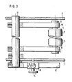
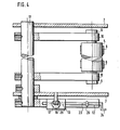
- the tensioning device has a pivot shaft 11 which is pivotably mounted in the feeder frame 7.
- bearing levers 10 are fixed, in which shaft journals 9 of the tensioning roller 5 are supported at their free ends, via which a number of pressure belts 8, not shown, runs.
- a clamping lever 12 is seated on the pivot shaft 11 in parallel association with the bearing levers 10. 21. displaced and in the set position on the clamping lever 12 with the aid of a handwheel .14 that actuates a clamping device (not shown).
- the holding member 13 On the upper side opposite the handle 21, the holding member 13 has a swivel joint 15, to which one end of a spring 17 is connected, the other end of which is articulated on the outside of one wall of the feed frame 7 in a joint 16.
- the strength in F. 2 spring 17 shown is a gas pressure spring, the piston rod 18 engages the joint 15.
- the threaded member moves the holding member 13 in one direction or the other in accordance with the double arrow 19 of FIG. 2.
- a locking of the respectively set position between the holding member 13 and the clamping lever 12 is not necessary as the position is maintained due to the friction of the thread engagement.
Landscapes
- Engineering & Computer Science (AREA)
- Mechanical Engineering (AREA)
- Delivering By Means Of Belts And Rollers (AREA)
- Sheets, Magazines, And Separation Thereof (AREA)
- Devices For Conveying Motion By Means Of Endless Flexible Members (AREA)
- Drives For Endless Conveyors (AREA)
Applications Claiming Priority (2)
| Application Number | Priority Date | Filing Date | Title |
|---|---|---|---|
| DE3218566 | 1982-05-17 | ||
| DE3218566A DE3218566C2 (de) | 1982-05-17 | 1982-05-17 | Spannvorrichtung für wenigstens ein einer Umlenktrommel eines Rundstapelbogenanlegers zugeordnetes Anpreßband |
Publications (2)
| Publication Number | Publication Date |
|---|---|
| EP0094523A1 true EP0094523A1 (fr) | 1983-11-23 |
| EP0094523B1 EP0094523B1 (fr) | 1985-08-07 |
Family
ID=6163857
Family Applications (1)
| Application Number | Title | Priority Date | Filing Date |
|---|---|---|---|
| EP83103931A Expired EP0094523B1 (fr) | 1982-05-17 | 1983-04-21 | Dispositif tendeur pour au moins un ruban de pression associé à une poulie de renvoi d'un margeur de feuilles rotary |
Country Status (5)
| Country | Link |
|---|---|
| US (1) | US4508214A (fr) |
| EP (1) | EP0094523B1 (fr) |
| JP (1) | JPS58216813A (fr) |
| CA (1) | CA1198457A (fr) |
| DE (1) | DE3218566C2 (fr) |
Families Citing this family (2)
| Publication number | Priority date | Publication date | Assignee | Title |
|---|---|---|---|---|
| DD267476A1 (de) * | 1987-11-30 | 1989-05-03 | Polygraph Leipzig | Verstelleinrichtung fuer anpressbaender |
| AT413692B (de) * | 2004-02-11 | 2006-05-15 | Tgw Transportgeraete Gmbh | Zugmitteltrieb, insbesondere für eine fördereinrichtung |
Citations (3)
| Publication number | Priority date | Publication date | Assignee | Title |
|---|---|---|---|---|
| DE2342615A1 (de) * | 1972-09-21 | 1974-03-28 | Grapha Holding Ag | Vorrichtung zum umsetzen eines papierbogenstapels in einen schuppenstrom |
| DE2628451A1 (de) * | 1975-07-07 | 1977-01-20 | Stobb Inc | Einrichtung zur zufuehrung von signaturen zu einer zusammentragemaschine |
| DE2516187B2 (de) * | 1974-04-16 | 1978-05-18 | International Business Machines Corp., Armonk, N.Y. (V.St.A.) | Magazin mit Vereinzelungsvorrichtung fur lochkartenförmige Aufzeichnungsträger |
Family Cites Families (11)
| Publication number | Priority date | Publication date | Assignee | Title |
|---|---|---|---|---|
| US1875442A (en) * | 1932-09-06 | Belt scraper | ||
| US832361A (en) * | 1905-12-20 | 1906-10-02 | Levi B Blevins | Conveyer-belt tightener for harvesters. |
| GB336737A (en) * | 1929-09-04 | 1930-10-23 | Colin Hugh Macmillan | Improvements in valve driving mechanism for internal combustion engines |
| US2833394A (en) * | 1953-11-12 | 1958-05-06 | Cordis Nat | Dual-belt elevator for poultry feeds |
| US2920751A (en) * | 1956-12-03 | 1960-01-12 | Gerbert Products Company | Chain tightener |
| US3142193A (en) * | 1961-11-20 | 1964-07-28 | Int Harvester Co | Belt tensioning device |
| US3214001A (en) * | 1962-10-09 | 1965-10-26 | Production Machinery Corp | Unscrambler |
| GB1090851A (en) * | 1964-01-14 | 1967-11-15 | John Douglas Dyson | Improvements in endless elevating conveyors |
| US3292772A (en) * | 1965-01-26 | 1966-12-20 | Burton Machine Corp John | Conveyor structure |
| GB1082266A (en) * | 1965-07-23 | 1967-09-06 | Gen Electric Co Ltd | Improvements in or relating to conveyor arrangements |
| US4089407A (en) * | 1977-01-31 | 1978-05-16 | K-Tron Corporation | Constant belt tensioner |
-
1982
- 1982-05-17 DE DE3218566A patent/DE3218566C2/de not_active Expired
-
1983
- 1983-04-21 EP EP83103931A patent/EP0094523B1/fr not_active Expired
- 1983-05-02 US US06/490,440 patent/US4508214A/en not_active Expired - Lifetime
- 1983-05-16 CA CA000428188A patent/CA1198457A/fr not_active Expired
- 1983-05-17 JP JP58086519A patent/JPS58216813A/ja active Pending
Patent Citations (3)
| Publication number | Priority date | Publication date | Assignee | Title |
|---|---|---|---|---|
| DE2342615A1 (de) * | 1972-09-21 | 1974-03-28 | Grapha Holding Ag | Vorrichtung zum umsetzen eines papierbogenstapels in einen schuppenstrom |
| DE2516187B2 (de) * | 1974-04-16 | 1978-05-18 | International Business Machines Corp., Armonk, N.Y. (V.St.A.) | Magazin mit Vereinzelungsvorrichtung fur lochkartenförmige Aufzeichnungsträger |
| DE2628451A1 (de) * | 1975-07-07 | 1977-01-20 | Stobb Inc | Einrichtung zur zufuehrung von signaturen zu einer zusammentragemaschine |
Also Published As
| Publication number | Publication date |
|---|---|
| DE3218566A1 (de) | 1983-11-17 |
| CA1198457A (fr) | 1985-12-24 |
| DE3218566C2 (de) | 1984-12-06 |
| US4508214A (en) | 1985-04-02 |
| EP0094523B1 (fr) | 1985-08-07 |
| JPS58216813A (ja) | 1983-12-16 |
Similar Documents
| Publication | Publication Date | Title |
|---|---|---|
| DE4013656C2 (de) | Vorrichtung zum Spleißen von Bahnen, insbesondere von Papierbahnen für die Herstellung von Wellpappe | |
| DE3126808C2 (fr) | ||
| DE19601470A1 (de) | Schleppsaugergetriebe, insbesondere Schleppsaugergetriebe für eine Vorrichtung zur Schrägbogenkorrektur | |
| CH694797A5 (de) | Doppeltwirkende Spreizeinrichtung zur Spreizung einer Bahn. | |
| DE69818754T2 (de) | Welleinrichtung, insbesondere für Blätter oder Bahnen aus Papier oder dergleichen | |
| EP0094523B1 (fr) | Dispositif tendeur pour au moins un ruban de pression associé à une poulie de renvoi d'un margeur de feuilles rotary | |
| DE3045051A1 (de) | Druckwerk fuer eine rollen-rotationsdruckmaschine | |
| EP1086916B1 (fr) | Unité de palier pour rouleaux tendeurs de bandes de matériau | |
| DE19519373A1 (de) | Falzapparat | |
| EP0475125B1 (fr) | Système de réglage de l'angle de phase entre un arbre entraînant et un arbre entraîné d'une transmission par chaîne dans une presse à imprimer pour feuilles | |
| DE10202798B4 (de) | Vorrichtung zum Verstellen von bahnführenden Walzen | |
| EP1112952B1 (fr) | Dispositif pour plier en continu de matériau plat | |
| DE4327012A1 (de) | Vorrichtung zur Betätigung seitlicher Bogenführungen an Rotationsdruckmaschinen | |
| DE19611787C2 (de) | Anordnung zum Falzen von Bögen | |
| DE3614264C2 (fr) | ||
| DE1561153C3 (de) | Vorrichtung zum Einstellen des Walzenabstandes an Falzmaschinen | |
| DE2337544C2 (de) | Rotationsvervielfältiger mit einer Bogenzuführvorrichtung | |
| DE2925066C2 (de) | Vorrichtung zum Falzen von Flachmaterial längs einer geraden Falzlinie | |
| DE2853741A1 (de) | Verfahren zur zufuehrung von bahnen aus papier zu einer falzmaschine sowie einrichtung zur durchfuehrung des verfahrens | |
| DE2435971A1 (de) | Vorrichtung zum laengsperforieren oder sicken von papierbahnen in druckmaschinen | |
| DE1574333B1 (de) | Vorrichtung zum verhueten von spannungsschwankungen in einer materialbahn | |
| EP0765746A1 (fr) | Machine d'impression et procédé d'alimentation en feuilles sous plusieurs cylindres d'impression | |
| DE2417041C3 (de) | Stauchfalzmaschine | |
| DE19611124A1 (de) | Bogenübertragungseinrichtung einer Bogenrotationsdruckmaschine | |
| DE19603030C2 (de) | Wechselvorrichtung |
Legal Events
| Date | Code | Title | Description |
|---|---|---|---|
| PUAI | Public reference made under article 153(3) epc to a published international application that has entered the european phase |
Free format text: ORIGINAL CODE: 0009012 |
|
| AK | Designated contracting states |
Designated state(s): FR GB IT |
|
| 17P | Request for examination filed |
Effective date: 19831024 |
|
| ITF | It: translation for a ep patent filed | ||
| GRAA | (expected) grant |
Free format text: ORIGINAL CODE: 0009210 |
|
| AK | Designated contracting states |
Designated state(s): FR GB IT |
|
| ET | Fr: translation filed | ||
| PLBE | No opposition filed within time limit |
Free format text: ORIGINAL CODE: 0009261 |
|
| STAA | Information on the status of an ep patent application or granted ep patent |
Free format text: STATUS: NO OPPOSITION FILED WITHIN TIME LIMIT |
|
| 26N | No opposition filed | ||
| ITTA | It: last paid annual fee | ||
| PGFP | Annual fee paid to national office [announced via postgrant information from national office to epo] |
Ref country code: GB Payment date: 19940329 Year of fee payment: 12 |
|
| PGFP | Annual fee paid to national office [announced via postgrant information from national office to epo] |
Ref country code: FR Payment date: 19940428 Year of fee payment: 12 |
|
| PG25 | Lapsed in a contracting state [announced via postgrant information from national office to epo] |
Ref country code: GB Effective date: 19950421 |
|
| GBPC | Gb: european patent ceased through non-payment of renewal fee |
Effective date: 19950421 |
|
| PG25 | Lapsed in a contracting state [announced via postgrant information from national office to epo] |
Ref country code: FR Effective date: 19951229 |
|
| REG | Reference to a national code |
Ref country code: FR Ref legal event code: ST |