EP0094533B1 - Méthode d'essai de fuite de tuyaux ou tuyautages - Google Patents
Méthode d'essai de fuite de tuyaux ou tuyautages Download PDFInfo
- Publication number
- EP0094533B1 EP0094533B1 EP83104218A EP83104218A EP0094533B1 EP 0094533 B1 EP0094533 B1 EP 0094533B1 EP 83104218 A EP83104218 A EP 83104218A EP 83104218 A EP83104218 A EP 83104218A EP 0094533 B1 EP0094533 B1 EP 0094533B1
- Authority
- EP
- European Patent Office
- Prior art keywords
- pressure
- pipe
- time
- difference
- standardised
- Prior art date
- Legal status (The legal status is an assumption and is not a legal conclusion. Google has not performed a legal analysis and makes no representation as to the accuracy of the status listed.)
- Expired
Links
- 238000000034 method Methods 0.000 title claims description 49
- 238000012360 testing method Methods 0.000 title claims description 16
- 238000005259 measurement Methods 0.000 claims description 37
- 238000004364 calculation method Methods 0.000 claims description 7
- 230000001419 dependent effect Effects 0.000 claims description 4
- 238000009530 blood pressure measurement Methods 0.000 claims description 3
- 239000000463 material Substances 0.000 claims description 2
- 239000012530 fluid Substances 0.000 claims 7
- 239000007788 liquid Substances 0.000 description 21
- 238000001514 detection method Methods 0.000 description 7
- 239000000446 fuel Substances 0.000 description 6
- 238000012544 monitoring process Methods 0.000 description 4
- 239000002689 soil Substances 0.000 description 4
- 230000007423 decrease Effects 0.000 description 3
- 230000006870 function Effects 0.000 description 3
- 239000010779 crude oil Substances 0.000 description 2
- 238000013461 design Methods 0.000 description 2
- 239000000428 dust Substances 0.000 description 2
- 230000000694 effects Effects 0.000 description 2
- 230000002123 temporal effect Effects 0.000 description 2
- 238000009529 body temperature measurement Methods 0.000 description 1
- 238000010586 diagram Methods 0.000 description 1
- 230000008030 elimination Effects 0.000 description 1
- 238000003379 elimination reaction Methods 0.000 description 1
- 238000011156 evaluation Methods 0.000 description 1
- 239000002828 fuel tank Substances 0.000 description 1
- 239000007789 gas Substances 0.000 description 1
- 238000009434 installation Methods 0.000 description 1
- 230000002045 lasting effect Effects 0.000 description 1
- 238000012886 linear function Methods 0.000 description 1
- 238000010606 normalization Methods 0.000 description 1
- 239000002245 particle Substances 0.000 description 1
- 230000002441 reversible effect Effects 0.000 description 1
- 239000004576 sand Substances 0.000 description 1
- 238000007619 statistical method Methods 0.000 description 1
- 239000000126 substance Substances 0.000 description 1
Images
Classifications
-
- G—PHYSICS
- G01—MEASURING; TESTING
- G01M—TESTING STATIC OR DYNAMIC BALANCE OF MACHINES OR STRUCTURES; TESTING OF STRUCTURES OR APPARATUS, NOT OTHERWISE PROVIDED FOR
- G01M3/00—Investigating fluid-tightness of structures
- G01M3/02—Investigating fluid-tightness of structures by using fluid or vacuum
- G01M3/26—Investigating fluid-tightness of structures by using fluid or vacuum by measuring rate of loss or gain of fluid, e.g. by pressure-responsive devices, by flow detectors
- G01M3/28—Investigating fluid-tightness of structures by using fluid or vacuum by measuring rate of loss or gain of fluid, e.g. by pressure-responsive devices, by flow detectors for pipes, cables or tubes; for pipe joints or seals; for valves ; for welds
- G01M3/2807—Investigating fluid-tightness of structures by using fluid or vacuum by measuring rate of loss or gain of fluid, e.g. by pressure-responsive devices, by flow detectors for pipes, cables or tubes; for pipe joints or seals; for valves ; for welds for pipes
- G01M3/2815—Investigating fluid-tightness of structures by using fluid or vacuum by measuring rate of loss or gain of fluid, e.g. by pressure-responsive devices, by flow detectors for pipes, cables or tubes; for pipe joints or seals; for valves ; for welds for pipes using pressure measurements
Definitions
- Pipes and pipe networks are understood here to mean all types of unbranched and branched lines of any cross section in which gas, liquids or dust particles are transported or which are intended for this are.
- the pressure test is made more difficult by the fact that pressure changes occur even without a leak if the pipe contents and pipe environment, eg soil, are not at the same temperature. Due to the temperature equalization processes taking place between the pipe contents and the pipe environment, the pressure in the pipe system or in the pipe section concerned rises or falls. This is the case, for example, at airports, where the fuel is stored in tanks and is distributed to taps via an underground pipe network with a pipe length of a few kilometers. Fueling processes constantly bring fuel with tank temperature into the pipe system, which is relatively cooler in summer and warmer in winter. In addition, the amounts of fuel in the individual pipe sections are stored for different lengths of time depending on the history of the fueling process and can therefore more or less adapt to the temperature of the surrounding soil.
- a temperature change of only 0.1 ° K in crude oil lines causes a pressure change of 1 bar regardless of the volume of the pipe network.
- the same pressure drop occurs, for example, in a pipe section containing 100 m 3 when approx. 101 have leaked. If one wants to find leaks / are less than or equal to 10 I h, then you have to entwe - the make sure the temperature that the pipe section to be much less than 0.1 ° K / changes h, or you have the mean temperature Determine very precisely in the pipe section and correct the pressure fluctuation caused by them.
- the invention has for its object to provide a method of the type mentioned, with which with little technical effort leaks - even those of relatively small size - can be detected safely and reliably in a short time even if the temperature of the pipe contents itself changes during the test process.
- the object is achieved according to the invention in a method for leak monitoring of the type defined in the preamble of claim 1 by the features in the characterizing part of claim 1.
- the method according to the invention is temperature-independent, so that neither the immense effort previously required for an extensive measuring point network for temperature measurement in the pipe system nor long waiting times for the temperature compensation between pipe content and pipe environment have to be accepted.
- temperature-related pressure changes are practically not dependent on the outlet pressure levels in the pipe section. Since the difference between the time-standardized pressure drops is formed at two different output pressure levels in the method according to the invention, lift the temperature-related parts largely emerge. This leads to absolutely reliable results as long as the measurement time, i.e. the sum of the duration of the measurement intervals, which are preferably immediately following one another, is very short compared to the half-life of a temperature compensation process between the inside and the outside of the pipe, and thus there is a quasi-linear pressure curve for the measurement time.
- the reliability of the method according to the invention can be determined by the further Increase design according to claim 5.
- An advantageous embodiment of the method according to the invention also results from claim 3.
- the regression calculation provided can be used to determine a pressure change in the case of superimposed statistical fluctuations in the pressure curve and / or the measured value display, which leads to usable results for leak testing and detection.
- K is the quotient of the maximum permissible leakage current (e.g. 1 I / h) and the square rooted pressure that occurs in the pipe network
- V the liquid volume in the closed pipe section
- t the time span
- p a1 and p a2 two different output pressure levels.
- the constant B is a quantity dependent on the geometry of the pipe network and is calculated according to
- Equation (1) can be used write: where u can assume a value between 0.3 and 0.8 depending on the type of flow in the leak and is 0.5 for pure turbulence.
- L is the leakage quantity
- (f) the leakage quantity escaping per unit of time, ie the leakage current, and p - as mentioned above - the maximum pressure occurring in the pipe network. If you want to detect leaks from a specified minimum size in pipe systems that are always at a constant operating pressure, as is the case with underground tank networks at airports, it is advisable to use the operating pressure p B of the pipe system for the pressure p instead of the maximum pressure that occurs.
- a further advantageous embodiment of the method according to the invention results from claim 8, also in conjunction with claim 9.
- the compensation of the creeping processes allows, on the one hand, a reduction in the false alarm rate and a more precise estimate of the leakage amount flowing out per unit of time, and, on the other hand, measurements in only short time intervals, whereby the measurement phases can begin a few minutes after the setting of the respective output pressure level and the distances between the settings, the so-called Measurement intervals need not be longer than 10 min.
- the constant C by which the difference in the outlet pressure levels is to be multiplied, is specific to the pipe network and can be determined empirically in accordance with a further embodiment of the invention according to claim 12 with the method steps specified therein. Tests have shown that the constant C is largely independent of the pipe network and pipe design, but is to a certain extent dependent on the structure of the soil surrounding the pipe network. For a pipe system embedded in sand, the constant C was determined to be 16. 10-6 S - 1 .
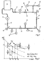
- the refueling system of an airport shown schematically in FIG. 1, has a pipe network 10 laid in the ground from a multiplicity of branched pipelines 11 connected to one another. At the end of the pipelines 11, some of which are stub lines, hydrants 12 are connected. The aircraft are refueled by so-called servicers who take off the fuel at the hydrant 12, clean it, reduce it to tank pressure and then direct it into the aircraft tank.
- the pipe network 10 is supplied with fuel from at least one main pump 13 from an above-ground fuel tank 14. The main pump 13 also ensures the necessary excess pressure in the pipes 11 of the pipe network 10.
- the pipe network 10 can be divided by means of a remotely controllable gate valve 15 into individual pipe sections with a predetermined liquid volume V. In Fig. 1, the pipe network 10 can be divided into four pipe sections A to D. A pressure sensor 16 for pressure measurement is provided in each pipe section.
- a leak test is carried out once a day in a longer, mostly several-hour refueling break in which fuel is not withdrawn from the pipe network 10 because of the stationary airport traffic.
- the pressure in all the pipes 11 of the pipe network 10 is set to a first outlet pressure level Pa1 of, for example, 9 bar.
- all gate valves 15 are closed, so that four hermetically sealed pipe sections A to D with a sufficiently small liquid volume in relation to the measuring accuracy and the maximum leakage flow permitted, which can be different in the individual pipe sections A to D and in the example is 40 m 3 , arise.
- the sufficiently small volume of liquid can be estimated from equation (1) if one knows the measuring accuracy of the pressure sensors 16 used and then defines the default value Ap.
- the constant K contains the permissible leakage current and B is determined by the geometry of the pipe network and the type of liquid.
- a pressure change difference .DELTA.p is now formed from the pressure changes .DELTA.p 1 and .DELTA.p 2 detected in the two measurement intervals and compared with a preset value .DELTA.p v . If there is a leak, the escaping leakage current depends on the overpressure in the pipe section. The higher this is, the greater the leakage losses. Since there are generally turbulent flow conditions at the outlet, the amount of leakage is a function of the root of the pressure difference between the pressure in the pipe system and the ambient pressure. The time course of the pressure results from the sizes agree with those given for equations (1) and (2). Due to the output pressure dependency of the leakage current, there is a pressure change difference in any case if there is a leak.
- the default value ⁇ p v can therefore be made 0.
- the default value ⁇ p v is calculated as described at the beginning and is, for example with a maximum permissible leakage current specification of 10 I / h, a liquid volume in the pipe section A of 40 m 3 , a measuring interval time of 10 min as the reference time unit and 0.147 bar for the specified two output pressures. If the pressure change difference Ap is greater than this preset value Ap., It can be concluded with certainty that there is a leak in the pipe section A. This process can be repeated several times, which significantly increases the reliability of the information.
- Fig. 2 two pressure profiles in the pipe section A are shown as a function of time. With this pressure curve, the assumption is made that there is no leak in pipe section A and the pressure drop is caused exclusively by a temperature gradient between the ground and the liquid in pipe section A. It is assumed that there is no longer a linear pressure curve over time.
- the pressure change here pressure drop
- the leakage quantity L flowing out through this leak under the operating condition of the pipe network 10 in the same time period of the measurement intervals, for example 10 minutes can be estimated in accordance with the following equation (4) the time-normalized pressure change difference measured in the measuring interval is multiplied by the reciprocal of the difference between the square root pressure levels p a1 and p a2 and multiplied by a constant.
- the constant x is system-specific and depends on the operating pressure p B of the pipe network 10 pending and is determined according to equation (5) wherein the constant B is calculated according to equation (2) and V represents the closed volume of the pipe section A.
- the estimation error for the leak quantity flowing out at the reference time unit is between -37 and + 49%, which is quite sufficient for assessing the leak size and the measures to be taken afterwards.
- the estimation error is based on the fact that in equations (4) and (5) again a turbulent flow in the leak is assumed.
- equations (4) and (5) the actual leak quantity flowing out in the reference time unit is where u can assume values between 0.3 and 0.8 depending on the type of flow in the leak and 0.5 for turbulence.
- the measured time-standardized pressure change difference Ap is reduced by a factor a before it is compared with the preset value Ap or used to estimate the leakage quantity L escaping per unit of time.
- the factor a depends on the difference between the outlet pressure levels p a and p a2 and is calculated according to equation (7)
- the constant C can be determined empirically by measuring the pressure change differences Ap occurring at measuring intervals on the dense network of pipes or on the individual pipe sections at a multiplicity of differently set outlet pressure levels Pal and Pa2 .
- the time-normalized pressure change differences are then plotted as a linear function of the difference between the outlet pressure levels p a1 and Pa2 , and the constant C is determined therefrom as the slope of the straight line according to equation (8)
- the invention is not restricted to the exemplary embodiment described above.
- the specified values for the time and pressure intervals are not mandatory, but rather adapted to the local conditions of the pipe network and the type and amount of the liquid. It is also not mandatory to determine the pressure change difference by setting an initially high and then low outlet pressure level in successive measurement intervals. The reverse setting of the outlet pressure levels brings the same results.
- the invention is also not restricted to the determination of the pressure change difference in two or three measuring intervals and to only two stages of the initial pressure level. In this way, several different output pressure levels can be set in several measuring intervals. The choice of measuring intervals of the same length of time is also not mandatory.
- the pressure changes, the pressure change difference and the default value and the estimated leakage quantity must be standardized, i.e. refer to the same unit of time. Recorded pressure changes must then be divided by the duration of the individual measurement intervals and multiplied by the reference time unit. None changes in the process. The calculation of the default value and the estimation of the leakage amount are then carried out with the reference time unit. It is equivalent to determining the slope of the pressure curve at predetermined times in the measurement interval, that is to say determining the time differential of the pressure.
- the method according to the invention is not only suitable for leak testing of liquid-filled pipes or pipe networks, as represented by the refueling system described.
- the method can also be used to test empty pipes or pipes intended for gas or dust transport for leaks.
- the pipes or pipe networks - if necessary divided into pipe sections - must be filled with liquid and sealed at the end.
Landscapes
- Physics & Mathematics (AREA)
- General Physics & Mathematics (AREA)
- Examining Or Testing Airtightness (AREA)
Claims (13)
Priority Applications (1)
| Application Number | Priority Date | Filing Date | Title |
|---|---|---|---|
| AT83104218T ATE18607T1 (de) | 1982-05-15 | 1983-04-29 | Verfahren zur leckpruefung von rohren oder rohrnetzen. |
Applications Claiming Priority (3)
| Application Number | Priority Date | Filing Date | Title |
|---|---|---|---|
| DE3218477 | 1982-05-15 | ||
| DE3218477 | 1982-05-15 | ||
| US06/547,096 US4608857A (en) | 1982-05-15 | 1983-10-31 | Method for checking pipes or pipe networks for leaks |
Publications (2)
| Publication Number | Publication Date |
|---|---|
| EP0094533A1 EP0094533A1 (fr) | 1983-11-23 |
| EP0094533B1 true EP0094533B1 (fr) | 1986-03-12 |
Family
ID=25801859
Family Applications (1)
| Application Number | Title | Priority Date | Filing Date |
|---|---|---|---|
| EP83104218A Expired EP0094533B1 (fr) | 1982-05-15 | 1983-04-29 | Méthode d'essai de fuite de tuyaux ou tuyautages |
Country Status (3)
| Country | Link |
|---|---|
| US (1) | US4608857A (fr) |
| EP (1) | EP0094533B1 (fr) |
| DE (1) | DE3316849A1 (fr) |
Families Citing this family (72)
| Publication number | Priority date | Publication date | Assignee | Title |
|---|---|---|---|---|
| EP0188911A3 (fr) * | 1984-12-25 | 1987-09-16 | Nippon Kokan Kabushiki Kaisha | Méthode et appareil pour détecter des fuites dans une canalisation de gaz |
| US4715214A (en) * | 1986-10-03 | 1987-12-29 | S. Himmelstein And Company | Leak tester |
| AU603644B2 (en) * | 1987-01-16 | 1990-11-22 | Saipem Australia Pty. Limited | Testing of pipelines |
| GB8707231D0 (en) * | 1987-03-26 | 1987-04-29 | Analytical Instr Ltd | Temperature compensation in pressure leak detection |
| GB8716032D0 (en) * | 1987-07-08 | 1987-08-12 | British Telecomm | Duct testing |
| US4876530A (en) * | 1987-10-13 | 1989-10-24 | The Marley Company | Method and apparatus for detecting leakage in fuel storage and delivery systems |
| DD294542A5 (de) * | 1989-05-19 | 1991-10-02 | Kk | Leckageueberwachung fuer hydraulische antriebssysteme |
| US5632269A (en) * | 1989-09-22 | 1997-05-27 | Respironics Inc. | Breathing gas delivery method and apparatus |
| DE3933265C2 (de) * | 1989-10-05 | 1993-11-04 | Walter Ludwig Behaelter Stahl | Verfahren und vorrichtung zur leckpruefung bei mehrwandigen druckbehaeltern |
| US5090234A (en) * | 1990-08-30 | 1992-02-25 | Vista Research, Inc. | Positive displacement pump apparatus and methods for detection of leaks in pressurized pipeline systems |
| US5078006A (en) * | 1990-08-30 | 1992-01-07 | Vista Research, Inc. | Methods for detection of leaks in pressurized pipeline systems |
| US5375455A (en) * | 1990-08-30 | 1994-12-27 | Vista Research, Inc. | Methods for measuring flow rates to detect leaks |
| US5317899A (en) * | 1992-12-11 | 1994-06-07 | Control Engineers, Inc. | Method for detecting leaks in underground product lines |
| GB9302958D0 (en) * | 1993-02-13 | 1993-03-31 | Lucas Ind Plc | Method of and apparatus for detecting fuel system leak |
| US5372032A (en) * | 1993-04-23 | 1994-12-13 | Filippi; Ernest A. | Pressurized piping line leak detector |
| US5361622A (en) * | 1993-09-09 | 1994-11-08 | The Shafer Valve Company | Device and method for detection of leaks in pressurized fluid vessels |
| US5377529A (en) * | 1993-11-15 | 1995-01-03 | Boyd; Mark A. | Leak detecting device, and method of constructing and utilizing same |
| US5450883A (en) * | 1994-02-07 | 1995-09-19 | Gilbarco, Inc. | System and method for testing for error conditions in a fuel vapor recovery system |
| GB9403184D0 (en) * | 1994-02-18 | 1994-04-06 | Boc Group Plc | Methods and apparatus for leak testing |
| US5557965A (en) * | 1994-10-20 | 1996-09-24 | Dover Corporation | Pipeline leak detector |
| US5526679A (en) * | 1995-01-05 | 1996-06-18 | Campo/Miller | Automatically calibrated pressurized piping leak detector |
| GB9505815D0 (en) * | 1995-03-22 | 1995-05-10 | British Gas Plc | Method of testing pipes for leakage |
| JP3543426B2 (ja) * | 1995-07-06 | 2004-07-14 | 株式会社日立製作所 | 管路網管理方法およびシステム |
| DE19609071C2 (de) * | 1996-03-08 | 2000-05-18 | Wtw Weilheim | Verfahren zur Fehlervermeidung bei der Messung oder Bestimmung des Gasverbrauchs von Materie |
| US6012482A (en) * | 1997-01-30 | 2000-01-11 | Djt Products, Inc. | Line break detector for pressurized fluid pumping systems |
| GB9711432D0 (en) * | 1997-06-04 | 1997-07-30 | British Gas Plc | Pipe leakage detection |
| US5948969A (en) * | 1997-10-20 | 1999-09-07 | Vista Research, Inc. | Methods for measuring the flow rate due to a leak in a pressurized pipe system |
| RU2155947C2 (ru) * | 1998-06-15 | 2000-09-10 | Камский политехнический институт | Способ определения расстояния до места негерметичности в длинномерных изделиях |
| SE513838C2 (sv) * | 1998-06-25 | 2000-11-13 | Gambro Lundia Ab | Metod jämte anordning för kalibrering av avkännande medel i ett system med ett strömmande fluidum |
| US6070452A (en) * | 1998-07-16 | 2000-06-06 | Brannan; Gene T. | Pipe leak locator with pressure gauge |
| EP1127256A1 (fr) * | 1998-10-07 | 2001-08-29 | Paavo Halmekytö Consulting Oy | Procede de detection de fuites dans des systemes de distribution d'eau |
| US6244100B1 (en) * | 1999-01-29 | 2001-06-12 | Caldon, Inc. | Temperature compensation for automated leak detection |
| US6311548B1 (en) * | 1999-08-25 | 2001-11-06 | Delphi Technologies, Inc. | Method of validating a diagnostic leak detection test for a fuel tank |
| DE19957998C2 (de) * | 1999-12-02 | 2001-10-18 | Josef Messmann Gmbh | Verfahren und Vorrichtung zum Prüfen von porösen Rohren o. dgl. auf Dichtheit |
| US6336479B1 (en) | 2000-02-07 | 2002-01-08 | Marconi Commerce Systems Inc. | Determining vapor recovery in a fueling system |
| US6549857B2 (en) | 2000-05-02 | 2003-04-15 | Vista Research, Inc. | Methods for detecting leaks in pressurized piping with a pressure measurement system |
| EP1452846A4 (fr) * | 2001-11-27 | 2011-04-13 | Aim Tech Co Ltd | Procede et dispositif de mesure de pression |
| DE10201109C1 (de) * | 2002-01-15 | 2003-01-23 | Fresenius Medical Care De Gmbh | Verfahren und Vorrichtung zur Detektion einer Leckage in einem Flüssigkeitssystem einer Blutbehandlungsvorrichtung |
| DE10242162A1 (de) * | 2002-09-10 | 2004-03-18 | Cegelec Anlagen- Und Automatisierungstechnik Gmbh & Co. Kg | Verfahren zur Leckprüfung von Rohren und Rohrsystemen |
| RU2227907C1 (ru) * | 2002-12-17 | 2004-04-27 | Белей Иван Васильевич | Способ испытания магистральных газопроводов |
| FR2849695B1 (fr) * | 2003-01-08 | 2005-06-03 | Michel Georges Andre Somnier | Procede de controle et de diagnostic de fuites sur un reseau de distribution d'un gaz |
| US7263873B2 (en) * | 2005-03-04 | 2007-09-04 | Robert Charles Richey | System and method for detecting leaks in pressurized piping systems |
| US7613584B2 (en) * | 2006-05-01 | 2009-11-03 | Hansa Consult Of North America, Llc | Methods, systems and computer program products for automatically detecting leaks in a hydrant fuel piping system |
| US8061360B2 (en) | 2006-09-19 | 2011-11-22 | Kci Licensing, Inc. | System and method for locating fluid leaks at a drape of a reduced pressure delivery system |
| US8366690B2 (en) * | 2006-09-19 | 2013-02-05 | Kci Licensing, Inc. | System and method for determining a fill status of a canister of fluid in a reduced pressure treatment system |
| US7438060B2 (en) * | 2006-11-17 | 2008-10-21 | General Motors Corporation | System for detecting purge valve malfunction |
| RU2380609C1 (ru) * | 2008-11-25 | 2010-01-27 | Дочернее Открытое Акционерное Общество (ДОАО) "Оргэнергогаз" | Установка для пневматических испытаний трубопровода и способ пневматических испытаний трубопровода (варианты) |
| NO329802B1 (no) * | 2009-02-24 | 2010-12-20 | Vemund Eithun | System og fremgangsmåte for lekkasjekontroll og/eller testing av rørnett og tappepunkter for ikke-komprimerbare væsker |
| US9207143B2 (en) | 2009-08-18 | 2015-12-08 | Innovative Pressure Testing, Llc | System and method for determining leaks in a complex system |
| US10031042B2 (en) | 2009-08-18 | 2018-07-24 | Innovative Pressure Testing, Llc | System and method for detecting leaks |
| WO2011022132A2 (fr) * | 2009-08-18 | 2011-02-24 | Franklin Charles M | Système et procédé de détection de fuites |
| US8682600B2 (en) | 2011-07-06 | 2014-03-25 | Saudi Arabian Oil Company | Pipeline leak detection and location system through pressure and cathodic protection soil |
| CN103245466A (zh) * | 2013-05-11 | 2013-08-14 | 中煤科工集团武汉设计研究院 | 长距离管道输煤清管试压方法 |
| CA2926187C (fr) | 2013-10-17 | 2020-01-07 | Innovative Pressure Testing, Llc | Systeme et procede pour un test de performances de pression |
| US9518461B2 (en) * | 2013-10-17 | 2016-12-13 | Innovative Pressure Testing, Llc | System and method for a pressure test |
| EP3058327B1 (fr) | 2013-10-17 | 2019-03-27 | Innovative Pressure Testing LLC | Système et procédé pour essai de pression étalon |
| JP6052197B2 (ja) * | 2014-02-05 | 2016-12-27 | Jfeスチール株式会社 | 監視装置および監視方法 |
| GB2553681B (en) * | 2015-01-07 | 2019-06-26 | Homeserve Plc | Flow detection device |
| WO2017053396A1 (fr) | 2015-09-21 | 2017-03-30 | AMI Investments, LLC | Surveillance à distance de système de distribution d'eau |
| US11988656B2 (en) | 2015-09-21 | 2024-05-21 | Mcwane, Inc. | Remote monitoring of water distribution system |
| DE102016106222A1 (de) | 2016-04-05 | 2017-10-05 | Krones Ag | Verfahren und Prüfvorrichtung zum automatischen Prüfen der Dichtheit eines Füllweges einer Füllvorrichtung sowie Füllvorrichtung |
| DE102017110112A1 (de) * | 2017-05-10 | 2018-11-15 | Grohe Ag | Verfahren zum Detektieren einer Leckage in einer Flüssigkeitsleitung sowie Wasserzähler mit einer Steuerung zur Durchführung des Verfahrens |
| GB2567180A (en) * | 2017-10-05 | 2019-04-10 | Homeserve Plc | Leak detection method and apparatus |
| JP6851953B2 (ja) * | 2017-10-30 | 2021-03-31 | アークレイ株式会社 | ポンプ駆動方法 |
| RU2669987C1 (ru) * | 2017-12-19 | 2018-10-17 | Общество с ограниченной ответственностью "Газпром трансгаз Самара" | Способ пневматического испытаний отключенного участка магистрального газопровода и устройство для его осуществления |
| DE102018128855A1 (de) | 2018-11-16 | 2020-05-20 | Viega Technology Gmbh & Co. Kg | Anordnung und Verfahren zum Detektieren von Leckagen in einem Wasserleitungssystem |
| US20210231516A1 (en) * | 2020-01-29 | 2021-07-29 | Water Hero Llc | Leak Detection System and Method |
| EP4196763B1 (fr) * | 2020-08-11 | 2026-07-22 | Clarke, Robert Turner | Appareil et procédé d'essai de pression |
| CN114251605A (zh) * | 2021-12-29 | 2022-03-29 | 东本电气科技(苏州)有限公司 | 一种燃气地下管网的检漏方法及应急装置 |
| CN114576568B (zh) * | 2022-02-25 | 2023-08-29 | 辽宁石油化工大学 | 基于次声波的管道泄漏检测方法及装置 |
| US12564748B2 (en) | 2022-08-05 | 2026-03-03 | Clow Valve Co. division of McWane, Inc. | Remote monitoring of water distribution system |
| CN117771535B (zh) * | 2024-01-09 | 2026-07-31 | 深圳核心医疗科技股份有限公司 | 基于输液装置的压强控制方法及装置 |
Family Cites Families (4)
| Publication number | Priority date | Publication date | Assignee | Title |
|---|---|---|---|---|
| FR2257080B1 (fr) * | 1974-01-08 | 1976-05-14 | Sud Ouest Ste Nationale Gaz | |
| DE2422561C2 (de) * | 1974-05-09 | 1983-11-03 | Hoechst Ag, 6230 Frankfurt | Vorrichtung zur Lecküberwachung einer Rohrleitung |
| DE2741546C2 (de) * | 1977-09-15 | 1983-07-07 | Hoechst Ag, 6230 Frankfurt | Verfahren zur Lecküberwachung von Rohrleitungen |
| JPS5827041A (ja) * | 1981-08-11 | 1983-02-17 | Hokuriku Electric Power Co Inc:The | パイプラインの漏洩検知方法 |
-
1983
- 1983-04-29 EP EP83104218A patent/EP0094533B1/fr not_active Expired
- 1983-05-07 DE DE19833316849 patent/DE3316849A1/de not_active Withdrawn
- 1983-10-31 US US06/547,096 patent/US4608857A/en not_active Expired - Lifetime
Also Published As
| Publication number | Publication date |
|---|---|
| DE3316849A1 (de) | 1983-11-17 |
| US4608857A (en) | 1986-09-02 |
| EP0094533A1 (fr) | 1983-11-23 |
Similar Documents
| Publication | Publication Date | Title |
|---|---|---|
| EP0094533A1 (fr) | Méthode d'essai de fuite de tuyaux ou tuyautages | |
| DE2422561C2 (de) | Vorrichtung zur Lecküberwachung einer Rohrleitung | |
| DE1922986C3 (de) | Verfahren zur Lecküberwachung von Flüssigkeitsleitungen | |
| EP0533960B1 (fr) | Dispositif et procédé pour la détection des fuites dans les canalisations doubles mures pour des milieux fluides | |
| EP3918296B1 (fr) | Procédé de détection d'une fuite dans un système de conduit et système de commande servant à mettre en oeuvre le procédé | |
| EP3760997A1 (fr) | Procédé et dispositif de mesure permettant de vérifier l'étanchéité de conduites d'eau | |
| EP2918894B1 (fr) | Dispositif et procédé de blocage de sécurité d'installations à gaz liquéfié | |
| DE2434872A1 (de) | Verfahren und vorrichtung zum erfassen eines lecks in einer pipeline | |
| EP0018536A1 (fr) | Indicateur de fissures pour la surveillance de l'isolation de réservoirs de stockage de gaz liquéfiés | |
| DE10242162A1 (de) | Verfahren zur Leckprüfung von Rohren und Rohrsystemen | |
| EP0661529B1 (fr) | Procédé et dispositif d'essai d'étanchéité d'un volume et pour déterminer la quantité de fuite | |
| DE4205453C2 (de) | Einrichtung zum Messen von hydraulischen Durchflußmengen und Leckagen an einem Prüfling | |
| EP0678735B1 (fr) | Dispositif de surveillance du débit d'un liquide | |
| DE102019129324A1 (de) | Detektion einer Leckage in einer Rohrleitung | |
| DE581053C (de) | Verfahren zur Ortsbestimmung undichter Stellen von Kanaelen, die in Hochspannungskabeln oder Kabelanlagen zur Aufnahme eines gasfoermigen Druckmittels angeordnet sind | |
| EP0638793B1 (fr) | Procédé et dispositif d'essai d'étanchéité de conduites ou appareils à gaz | |
| DE3815308C2 (fr) | ||
| DE2741546C2 (de) | Verfahren zur Lecküberwachung von Rohrleitungen | |
| CH623911A5 (fr) | ||
| DE29707328U1 (de) | Luftdruckprüfgerät zur Prüfung der Dichtigkeit von verlegten Kanalisationsrohren | |
| DE3907490A1 (de) | Vorrichtung zur leckueberwachung einer mit einem fluid gefuellten rohrleitung | |
| DE3910016C2 (fr) | ||
| DE4416639B4 (de) | Verfahren und Anordnung zur Dichtigkeitsprüfung von Gasrohrleitungen und Gasgeräten | |
| DE2802930C3 (de) | Vorrichtung zur Dichtheitsprüfung von mit Flüssigkeit gefüllten Behältern, insbesondere Flachbodentanks mit großem Fassungsvermögen zur Lagerung von flüssigen Mineralölprodukten u.dgl. | |
| DE19947992A1 (de) | Verfahren und Messanlage zur Überprüfung eines Durchflussmessers im eingebauten Zustand |
Legal Events
| Date | Code | Title | Description |
|---|---|---|---|
| PUAI | Public reference made under article 153(3) epc to a published international application that has entered the european phase |
Free format text: ORIGINAL CODE: 0009012 |
|
| AK | Designated contracting states |
Designated state(s): AT BE CH DE FR GB IT LI NL SE |
|
| 17P | Request for examination filed |
Effective date: 19831130 |
|
| ITF | It: translation for a ep patent filed | ||
| GRAA | (expected) grant |
Free format text: ORIGINAL CODE: 0009210 |
|
| AK | Designated contracting states |
Kind code of ref document: B1 Designated state(s): AT BE CH DE FR GB IT LI NL SE |
|
| REF | Corresponds to: |
Ref document number: 18607 Country of ref document: AT Date of ref document: 19860315 Kind code of ref document: T |
|
| REF | Corresponds to: |
Ref document number: 3362508 Country of ref document: DE Date of ref document: 19860417 |
|
| ET | Fr: translation filed | ||
| PLBE | No opposition filed within time limit |
Free format text: ORIGINAL CODE: 0009261 |
|
| STAA | Information on the status of an ep patent application or granted ep patent |
Free format text: STATUS: NO OPPOSITION FILED WITHIN TIME LIMIT |
|
| 26N | No opposition filed | ||
| ITTA | It: last paid annual fee | ||
| REG | Reference to a national code |
Ref country code: CH Ref legal event code: PUE Owner name: ATLAS ELEKTRONIK GMBH Ref country code: CH Ref legal event code: PFA Free format text: FRIED. KRUPP AG |
|
| REG | Reference to a national code |
Ref country code: GB Ref legal event code: 732 |
|
| BECH | Be: change of holder |
Free format text: 921216 *ATLAS ELEKTRONIK G.M.B.H. |
|
| REG | Reference to a national code |
Ref country code: FR Ref legal event code: TP Ref country code: FR Ref legal event code: CN Ref country code: FR Ref legal event code: CD |
|
| ITPR | It: changes in ownership of a european patent |
Owner name: CAMBIO RAGIONE SOCIALE;FRIED. KRUPP AG |
|
| NLS | Nl: assignments of ep-patents |
Owner name: FRIED. KRUPP AG TE ESSEN, BONDSREPUBLIEK DUITSLAND |
|
| NLS | Nl: assignments of ep-patents |
Owner name: ATLAS ELEKTRONIK GMBH TE BREMEN, BONDSREPUBLIEK DU |
|
| EAL | Se: european patent in force in sweden |
Ref document number: 83104218.9 |
|
| PGFP | Annual fee paid to national office [announced via postgrant information from national office to epo] |
Ref country code: GB Payment date: 19980323 Year of fee payment: 16 |
|
| PGFP | Annual fee paid to national office [announced via postgrant information from national office to epo] |
Ref country code: AT Payment date: 19980327 Year of fee payment: 16 |
|
| PGFP | Annual fee paid to national office [announced via postgrant information from national office to epo] |
Ref country code: FR Payment date: 19980420 Year of fee payment: 16 |
|
| PGFP | Annual fee paid to national office [announced via postgrant information from national office to epo] |
Ref country code: SE Payment date: 19980427 Year of fee payment: 16 Ref country code: BE Payment date: 19980427 Year of fee payment: 16 |
|
| PGFP | Annual fee paid to national office [announced via postgrant information from national office to epo] |
Ref country code: NL Payment date: 19980430 Year of fee payment: 16 |
|
| PGFP | Annual fee paid to national office [announced via postgrant information from national office to epo] |
Ref country code: CH Payment date: 19980518 Year of fee payment: 16 |
|
| PG25 | Lapsed in a contracting state [announced via postgrant information from national office to epo] |
Ref country code: GB Free format text: LAPSE BECAUSE OF NON-PAYMENT OF DUE FEES Effective date: 19990429 Ref country code: AT Free format text: LAPSE BECAUSE OF NON-PAYMENT OF DUE FEES Effective date: 19990429 |
|
| PG25 | Lapsed in a contracting state [announced via postgrant information from national office to epo] |
Ref country code: SE Free format text: LAPSE BECAUSE OF NON-PAYMENT OF DUE FEES Effective date: 19990430 Ref country code: LI Free format text: LAPSE BECAUSE OF NON-PAYMENT OF DUE FEES Effective date: 19990430 Ref country code: CH Free format text: LAPSE BECAUSE OF NON-PAYMENT OF DUE FEES Effective date: 19990430 Ref country code: BE Free format text: LAPSE BECAUSE OF NON-PAYMENT OF DUE FEES Effective date: 19990430 |
|
| BERE | Be: lapsed |
Owner name: ATLAS ELEKTRONIK G.M.B.H. Effective date: 19990430 |
|
| PG25 | Lapsed in a contracting state [announced via postgrant information from national office to epo] |
Ref country code: NL Free format text: LAPSE BECAUSE OF NON-PAYMENT OF DUE FEES Effective date: 19991101 |
|
| REG | Reference to a national code |
Ref country code: CH Ref legal event code: PL |
|
| GBPC | Gb: european patent ceased through non-payment of renewal fee |
Effective date: 19990429 |
|
| PG25 | Lapsed in a contracting state [announced via postgrant information from national office to epo] |
Ref country code: FR Free format text: LAPSE BECAUSE OF NON-PAYMENT OF DUE FEES Effective date: 19991231 |
|
| NLV4 | Nl: lapsed or anulled due to non-payment of the annual fee |
Effective date: 19991101 |
|
| EUG | Se: european patent has lapsed |
Ref document number: 83104218.9 |
|
| REG | Reference to a national code |
Ref country code: FR Ref legal event code: ST |
|
| PGFP | Annual fee paid to national office [announced via postgrant information from national office to epo] |
Ref country code: DE Payment date: 20020503 Year of fee payment: 20 |