EP0094537B1 - Outil de tronçonnage simple et multiple - Google Patents
Outil de tronçonnage simple et multiple Download PDFInfo
- Publication number
- EP0094537B1 EP0094537B1 EP83104266A EP83104266A EP0094537B1 EP 0094537 B1 EP0094537 B1 EP 0094537B1 EP 83104266 A EP83104266 A EP 83104266A EP 83104266 A EP83104266 A EP 83104266A EP 0094537 B1 EP0094537 B1 EP 0094537B1
- Authority
- EP
- European Patent Office
- Prior art keywords
- cutting
- tool
- clamping
- recess
- plates
- Prior art date
- Legal status (The legal status is an assumption and is not a legal conclusion. Google has not performed a legal analysis and makes no representation as to the accuracy of the status listed.)
- Expired
Links
- 230000002441 reversible effect Effects 0.000 claims 1
- 230000000153 supplemental effect Effects 0.000 abstract 1
- 241000047428 Halter Species 0.000 description 1
- 230000006835 compression Effects 0.000 description 1
- 238000007906 compression Methods 0.000 description 1
- 238000006073 displacement reaction Methods 0.000 description 1
- 238000000034 method Methods 0.000 description 1
- 238000004806 packaging method and process Methods 0.000 description 1
- 230000000149 penetrating effect Effects 0.000 description 1
- 230000001681 protective effect Effects 0.000 description 1
- 230000000284 resting effect Effects 0.000 description 1
Images

Classifications
-
- B—PERFORMING OPERATIONS; TRANSPORTING
- B23—MACHINE TOOLS; METAL-WORKING NOT OTHERWISE PROVIDED FOR
- B23B—TURNING; BORING
- B23B27/00—Tools for turning or boring machines; Tools of a similar kind in general; Accessories therefor
- B23B27/04—Cutting-off tools
-
- B—PERFORMING OPERATIONS; TRANSPORTING
- B23—MACHINE TOOLS; METAL-WORKING NOT OTHERWISE PROVIDED FOR
- B23B—TURNING; BORING
- B23B29/00—Holders for non-rotary cutting tools; Boring bars or boring heads; Accessories for tool holders
- B23B29/04—Tool holders for a single cutting tool
- B23B29/043—Tool holders for a single cutting tool with cutting-off, grooving or profile cutting tools, i.e. blade- or disc-like main cutting parts
-
- B—PERFORMING OPERATIONS; TRANSPORTING
- B23—MACHINE TOOLS; METAL-WORKING NOT OTHERWISE PROVIDED FOR
- B23B—TURNING; BORING
- B23B2205/00—Fixation of cutting inserts in holders
- B23B2205/16—Shims
-
- B—PERFORMING OPERATIONS; TRANSPORTING
- B23—MACHINE TOOLS; METAL-WORKING NOT OTHERWISE PROVIDED FOR
- B23B—TURNING; BORING
- B23B2210/00—Details of turning tools
- B23B2210/02—Tool holders having multiple cutting inserts
- B23B2210/022—Grooving tools
-
- B—PERFORMING OPERATIONS; TRANSPORTING
- B23—MACHINE TOOLS; METAL-WORKING NOT OTHERWISE PROVIDED FOR
- B23B—TURNING; BORING
- B23B2220/00—Details of turning, boring or drilling processes
- B23B2220/28—Parting off and chamferring simultaneously
-
- B—PERFORMING OPERATIONS; TRANSPORTING
- B23—MACHINE TOOLS; METAL-WORKING NOT OTHERWISE PROVIDED FOR
- B23B—TURNING; BORING
- B23B2260/00—Details of constructional elements
- B23B2260/004—Adjustable elements
-
- Y—GENERAL TAGGING OF NEW TECHNOLOGICAL DEVELOPMENTS; GENERAL TAGGING OF CROSS-SECTIONAL TECHNOLOGIES SPANNING OVER SEVERAL SECTIONS OF THE IPC; TECHNICAL SUBJECTS COVERED BY FORMER USPC CROSS-REFERENCE ART COLLECTIONS [XRACs] AND DIGESTS
- Y10—TECHNICAL SUBJECTS COVERED BY FORMER USPC
- Y10T—TECHNICAL SUBJECTS COVERED BY FORMER US CLASSIFICATION
- Y10T407/00—Cutters, for shaping
- Y10T407/22—Cutters, for shaping including holder having seat for inserted tool
- Y10T407/2208—Plural simultaneously usable separable tools in common seat or common clamp actuator for plural simultaneously usable tools
-
- Y—GENERAL TAGGING OF NEW TECHNOLOGICAL DEVELOPMENTS; GENERAL TAGGING OF CROSS-SECTIONAL TECHNOLOGIES SPANNING OVER SEVERAL SECTIONS OF THE IPC; TECHNICAL SUBJECTS COVERED BY FORMER USPC CROSS-REFERENCE ART COLLECTIONS [XRACs] AND DIGESTS
- Y10—TECHNICAL SUBJECTS COVERED BY FORMER USPC
- Y10T—TECHNICAL SUBJECTS COVERED BY FORMER US CLASSIFICATION
- Y10T407/00—Cutters, for shaping
- Y10T407/22—Cutters, for shaping including holder having seat for inserted tool
- Y10T407/2266—Holder adapted for tools of different shape
-
- Y—GENERAL TAGGING OF NEW TECHNOLOGICAL DEVELOPMENTS; GENERAL TAGGING OF CROSS-SECTIONAL TECHNOLOGIES SPANNING OVER SEVERAL SECTIONS OF THE IPC; TECHNICAL SUBJECTS COVERED BY FORMER USPC CROSS-REFERENCE ART COLLECTIONS [XRACs] AND DIGESTS
- Y10—TECHNICAL SUBJECTS COVERED BY FORMER USPC
- Y10T—TECHNICAL SUBJECTS COVERED BY FORMER US CLASSIFICATION
- Y10T407/00—Cutters, for shaping
- Y10T407/22—Cutters, for shaping including holder having seat for inserted tool
- Y10T407/2272—Cutters, for shaping including holder having seat for inserted tool with separate means to fasten tool to holder
-
- Y—GENERAL TAGGING OF NEW TECHNOLOGICAL DEVELOPMENTS; GENERAL TAGGING OF CROSS-SECTIONAL TECHNOLOGIES SPANNING OVER SEVERAL SECTIONS OF THE IPC; TECHNICAL SUBJECTS COVERED BY FORMER USPC CROSS-REFERENCE ART COLLECTIONS [XRACs] AND DIGESTS
- Y10—TECHNICAL SUBJECTS COVERED BY FORMER USPC
- Y10T—TECHNICAL SUBJECTS COVERED BY FORMER US CLASSIFICATION
- Y10T407/00—Cutters, for shaping
- Y10T407/22—Cutters, for shaping including holder having seat for inserted tool
- Y10T407/2272—Cutters, for shaping including holder having seat for inserted tool with separate means to fasten tool to holder
- Y10T407/2282—Cutters, for shaping including holder having seat for inserted tool with separate means to fasten tool to holder including tool holding clamp and clamp actuator
-
- Y—GENERAL TAGGING OF NEW TECHNOLOGICAL DEVELOPMENTS; GENERAL TAGGING OF CROSS-SECTIONAL TECHNOLOGIES SPANNING OVER SEVERAL SECTIONS OF THE IPC; TECHNICAL SUBJECTS COVERED BY FORMER USPC CROSS-REFERENCE ART COLLECTIONS [XRACs] AND DIGESTS
- Y10—TECHNICAL SUBJECTS COVERED BY FORMER USPC
- Y10T—TECHNICAL SUBJECTS COVERED BY FORMER US CLASSIFICATION
- Y10T407/00—Cutters, for shaping
- Y10T407/23—Cutters, for shaping including tool having plural alternatively usable cutting edges
Definitions
- the invention relates to a single or multiple plunging tool with detachably clampable in a recess of a holder cutting plates, which by means of a substantially L-shaped, the cutting plate or a cutting plate package from above and one side overlapping bracket against the bottom and a side wall of the recess be clamped, a clamping force component of the clamping bracket being generated transversely to the side wall when the clamping bracket is braced against the floor via a wedge ramp.
- Such a lancing tool which has become known from US Pat. No. 3,675,291, has the advantage that not only are the cutting plates pressed down against the bottom of the holder recess by the actuation of the clamping screw, but at the same time are braced against one another as a package by the transverse component produced in the process .
- the difficulty with this previously known piercing tool is, firstly, that the additional cutting plates provided with a rib are suspended on the top of the main cutting plate and that exact positioning - i.e. H. the distances of the cutting edges of the different plates from each other - difficult adjustment work required and there is a risk that this adjustment will be adjusted due to the stresses in operation.
- the invention is therefore based on the object of designing a lancing tool of the type described above in such a way that the cutting plate can be clamped quickly and in a precise position, so that no cumbersome adjustment work is required even when turning or replacing the cutting plate.
- adjusting ribs engaging in the fitting grooves of all cutting inserts are arranged on the bottom of the recess and / or the underside of the upper clamping leg of the clamping bracket.
- fitting grooves according to the invention which are arranged centrally in the preferred use of indexable inserts and ground in with a precise fit with respect to the cutting edges, in connection with the end inserts between the various inserts, the system has a very simple repeatability without the slightest adjustment work having to be carried out .
- the generation of the clamping force component transversely to the side wall can be achieved according to a first embodiment of the inventive concept in that a non-self-clamping wedge is interposed between the side of the plate of the clamping bracket and the leg of the clamping bracket widening downwards, which widen downwards, and the opposite wall of the recess.
- a non-self-clamping wedge is interposed between the side of the plate of the clamping bracket and the leg of the clamping bracket widening downwards, which widen downwards, and the opposite wall of the recess.
- the inner angle of the clamping bracket should be somewhat smaller than 90 ° in an embodiment of the invention, so that the retaining bracket is placed like a collet around the interchangeable plate pack.
- a clamping screw which can be screwed, for example, laterally next to the clamping wedge into a threaded hole in the holder and with its head either engages over the clamping wedge or engages in a lateral flute of the clamping wedge.
- a guide pin which engages in a bore of the clamping wedge and is fastened in the holder can be provided.
- a clamping screw can also be provided to further increase the clamping security for fixing the free end of the upper clamping leg of the clamping bracket that lies on the holder next to the recess.
- the tightening of this screw which of course has to pass through the upper clamping leg to enable the plate pack to be pressed together, takes place only after the clamping wedge has been braced.
- the generation of the clamping force component of the tensioning bracket transverse to the side wall can also be achieved in that a transverse tensioning cam supported on a wedge ramp of the holder is provided at the free end of the leg of the tensioning bracket which overlaps the plate or the plate pack and that a clamping screw penetrating the leg in an elongated hole engages in a threaded bore of the holder between this ramp and the side wall.
- a transverse tensioning cam supported on a wedge ramp of the holder is provided at the free end of the leg of the tensioning bracket which overlaps the plate or the plate pack and that a clamping screw penetrating the leg in an elongated hole engages in a threaded bore of the holder between this ramp and the side wall.
- the adjusting rib prefferably be formed on a base plate which fills the base area of the recess and is held by a bolt passing through it, in particular the guide bolt of the clamping wedge, so that the flutes must be arranged on the underside of the plates.
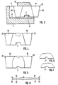
- a support plate 5 is held by means of a bolt 6 passing through it, on the upper side of which an adjusting rib 5 'is formed.
- the adjusting rib 5 ' engages in fitting grooves 7 of cutting plates 8 to 11 designed as indexable inserts, which are held with the help of end-shaped shim plates 12 to 14 and a protective outer shim 15 with the help of a clamping bracket 16.
- the clamping bracket 16 is essentially L-shaped, with the upper clamping leg 17 resting on the plate pack, while the second leg 18 of the plate pack, which widens in a wedge-shaped manner towards its free end, lies laterally.
- the clamping bracket 16 is tensioned, the inside angle of which is somewhat less than 90 °. It is thereby achieved that the upper clamping leg 17 is first pressed down at its end and thus finally pressed onto the plate pack in a clamping manner before the plate pack is pressed in the direction of the side wall 21 of the recess 4.
- the system results in exact repeatability, both when the plates are turned and when they are exchanged, without any special adjustment effort.
- FIG. 2 shows a multi-plunger tool in which the grooving plates 8 'and 10' break the edges of the groove which is machined into the workpiece by the grooving plate 9 ', while at a precise distance therefrom, which is defined by the gauge plate 23 results in the cutting plate 11 'incorporating a further, but less deep groove into the workpiece.
- FIGS. 4 and 5 are different shapes. of the fitting grooves 7, T, 7 "and 7" ', dashed lines in FIGS. 4 and 5 also indicate the possibility of accommodating these grooves in the top of the grooving plates, which would however make it necessary to adjust the adjusting rib 5' to form on the underside of the leg 17.
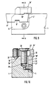
- FIGS. 9 and 10 show a single piercing tool with a recess 4 'of the holder 1 which is open on three sides.
- the clamping bracket 16' is at the end opposite the shortened leg 18 'which bears against the side face of the cutting plate 8' 'by means of a threaded screw provided with a conical tip 24 transverse tensioning cams 25 which are supported on an inclined ramp 26 of the holder 1.
- the middle part of the plates and the cutting ends have exactly the same thickness a (which is indicated in FIG. 8), but it is also advantageous if one distinguishes between the precisely fitting middle section and the cutouts provides recesses 32 so that the cutting edges of adjacent plates are exposed laterally and do not abut the neighboring plate.
- the cutting edges can therefore have a somewhat larger width, since they then come to rest in the region of the recesses 32 of the adjacent plates.
Landscapes
- Engineering & Computer Science (AREA)
- Mechanical Engineering (AREA)
- Cutting Tools, Boring Holders, And Turrets (AREA)
- Connection Of Plates (AREA)
- Knives (AREA)
- Clamps And Clips (AREA)
- Processing Of Stones Or Stones Resemblance Materials (AREA)
Claims (14)
Priority Applications (1)
| Application Number | Priority Date | Filing Date | Title |
|---|---|---|---|
| AT83104266T ATE22023T1 (de) | 1982-05-19 | 1983-04-30 | Ein- und mehrfachstechwerkzeug. |
Applications Claiming Priority (2)
| Application Number | Priority Date | Filing Date | Title |
|---|---|---|---|
| DE3219019 | 1982-05-19 | ||
| DE3219019A DE3219019A1 (de) | 1982-05-19 | 1982-05-19 | Ein- und mehrfachstechwerkzeug |
Publications (2)
| Publication Number | Publication Date |
|---|---|
| EP0094537A1 EP0094537A1 (fr) | 1983-11-23 |
| EP0094537B1 true EP0094537B1 (fr) | 1986-09-10 |
Family
ID=6164102
Family Applications (1)
| Application Number | Title | Priority Date | Filing Date |
|---|---|---|---|
| EP83104266A Expired EP0094537B1 (fr) | 1982-05-19 | 1983-04-30 | Outil de tronçonnage simple et multiple |
Country Status (5)
| Country | Link |
|---|---|
| US (1) | US4573832A (fr) |
| EP (1) | EP0094537B1 (fr) |
| JP (1) | JPS58211801A (fr) |
| AT (1) | ATE22023T1 (fr) |
| DE (2) | DE3219019A1 (fr) |
Families Citing this family (16)
| Publication number | Priority date | Publication date | Assignee | Title |
|---|---|---|---|---|
| US4509886A (en) * | 1983-11-25 | 1985-04-09 | Lindsay Harold W | Cutting tool with cutting inserts having positioning keyways |
| SE504314C2 (sv) * | 1992-04-28 | 1997-01-13 | Sandvik Ab | Skärförsett verktyg för avstickning eller liknande svarvningsoperationer samt underläggselement för skär till dylika verktyg |
| US5370023A (en) * | 1992-09-09 | 1994-12-06 | Gte Products Corporation | Cutting tool for turning parallel grooves |
| US5322395A (en) * | 1992-12-09 | 1994-06-21 | Cole Larry M | Datum point form tool |
| US5345846A (en) * | 1993-03-22 | 1994-09-13 | Somma Tool Company, Inc. | Tool holder with resharpenable form tool insert |
| US5924826A (en) * | 1994-04-27 | 1999-07-20 | Sandvik Ab | Cutting insert mounted on holder by rib-and-groove coupling |
| DE4415425A1 (de) * | 1994-05-03 | 1995-11-09 | Krupp Widia Gmbh | Spanendes Werkzeug |
| SE509363C2 (sv) * | 1995-09-25 | 1999-01-18 | Sandvik Ab | Fastspänningsanordning fjör skärplattor samt skärplatta avsedd för dylik anordning |
| US5942295A (en) * | 1997-10-01 | 1999-08-24 | International Paper Co. | Polyester paperboard ovenable container |
| US6068897A (en) * | 1997-10-01 | 2000-05-30 | International Paper Company | Dual ovenable paperboard structures having unique adhesive tie materials |
| US5968647A (en) * | 1997-10-01 | 1999-10-19 | International Paper Company | Enhanced ethylene methyl acrylate adhesive tie material for polyester paperboard ovenable container |
| DE10012821A1 (de) * | 2000-03-16 | 2001-09-20 | Sandvik Ab | Schneidplattenhalter für Drehwerkzeug sowie Stechplatte hierfür |
| DE50110198D1 (de) * | 2000-03-16 | 2006-08-03 | Sandvik Intellectual Property | Schneidplattenhalter für Drehwerkzeuge sowie Stechplatten hierfür |
| DE102006052701A1 (de) * | 2006-01-09 | 2007-07-26 | Ceramtec Ag Innovative Ceramic Engineering | Formschlüssig befestigte Schneidplatte auf einer Stützplatte |
| US9033622B2 (en) | 2012-01-03 | 2015-05-19 | Iscar, Ltd. | Cutting insert having curved ramps for insertion into a tool holder, cutting tool and method of assembly |
| CN108672729A (zh) * | 2018-08-07 | 2018-10-19 | 陈耀龙 | 大行程高灵敏度车刀刀尖高度精密调整装置 |
Family Cites Families (17)
| Publication number | Priority date | Publication date | Assignee | Title |
|---|---|---|---|---|
| US1336155A (en) * | 1919-03-14 | 1920-04-06 | Clarence S Luitwieler | Tool-holder |
| US1396180A (en) * | 1920-07-15 | 1921-11-08 | Continental Motors Corp | Cutting-tool |
| DE617343C (de) * | 1932-12-04 | 1935-08-16 | Winter & Sohn Ernst | Vorrichtung zum genauen seitlichen Einstellen von Mehrfach-Schlichtwerkzeugen, insbesondere Diamantwerkzeugen |
| US2142517A (en) * | 1936-12-21 | 1939-01-03 | Ingersoll Milling Machine Co | Metal working |
| US2289155A (en) * | 1940-09-12 | 1942-07-07 | Samuel Briskman | Tool holder |
| US2498721A (en) * | 1945-06-07 | 1950-02-28 | Stephen M Stafford | Hob |
| US2497228A (en) * | 1946-06-21 | 1950-02-14 | Leon B Miller | Groove scraping device |
| FR1044242A (fr) * | 1950-10-30 | 1953-11-16 | Outil à rainurer de largeur réglable, pour tour | |
| US3132542A (en) * | 1962-03-27 | 1964-05-12 | Paul M Horvath | Cutter having a removable tip |
| US3289272A (en) * | 1964-10-13 | 1966-12-06 | Willeys Carbide Tool Co | Cutting tools with throw-away inserts |
| US3675291A (en) * | 1971-02-19 | 1972-07-11 | Empire Tool Co | Combination cut-off and chamfer tool |
| US3760474A (en) * | 1971-11-04 | 1973-09-25 | Warner Swasey Co | Reversible blade-like cutoff tool |
| US3805350A (en) * | 1972-11-29 | 1974-04-23 | Warner Swasey Co | Cutoff insert apparatus |
| US3887974A (en) * | 1974-08-01 | 1975-06-10 | Kennametal Inc | Cutting insert and holder therefor |
| US4063841A (en) * | 1976-07-08 | 1977-12-20 | Posa-Cut Corporation | Indexable insert for grooving tools |
| US4078868A (en) * | 1977-04-06 | 1978-03-14 | The Ingersoll Milling Machine Company | Cutter having inserts clamped with wedges |
| GB2085333B (en) * | 1980-10-13 | 1985-03-06 | Sandvik Ltd | Cutting inserts and tools provided with replaceable cutting inserts |
-
1982
- 1982-05-19 DE DE3219019A patent/DE3219019A1/de not_active Withdrawn
-
1983
- 1983-04-30 DE DE8383104266T patent/DE3365993D1/de not_active Expired
- 1983-04-30 EP EP83104266A patent/EP0094537B1/fr not_active Expired
- 1983-04-30 AT AT83104266T patent/ATE22023T1/de not_active IP Right Cessation
- 1983-05-05 US US06/491,627 patent/US4573832A/en not_active Expired - Lifetime
- 1983-05-19 JP JP58089044A patent/JPS58211801A/ja active Pending
Also Published As
| Publication number | Publication date |
|---|---|
| ATE22023T1 (de) | 1986-09-15 |
| DE3219019A1 (de) | 1983-11-24 |
| EP0094537A1 (fr) | 1983-11-23 |
| DE3365993D1 (en) | 1986-10-16 |
| JPS58211801A (ja) | 1983-12-09 |
| US4573832A (en) | 1986-03-04 |
Similar Documents
| Publication | Publication Date | Title |
|---|---|---|
| EP0094537B1 (fr) | Outil de tronçonnage simple et multiple | |
| DE69516971T2 (de) | Halterungsvorrichtung | |
| DE2339873C2 (de) | Anordnung zum Einstellen und Befestigen eines ein Schneidplättchen tragenden Blocks in einer nutförmigen Aufnahme im Werkzeugkörper eines spanabhebenden Werkzeugs | |
| EP0602204B1 (fr) | Element intermediaire pour dispositifs de serrage sur plaques a matrice de trous de machine-outil | |
| DE69212871T2 (de) | Spannvorrichtung | |
| EP0126432A1 (fr) | Outil de fraisage | |
| DE2411759B2 (de) | Schneidwerkzeug fuer die spanabhebende bearbeitung | |
| EP0381924B1 (fr) | Alésoir | |
| EP2771142A1 (fr) | Système d'outil | |
| EP1764168A1 (fr) | Ensemble coulisseau pour une camme arienne | |
| DE3140905C2 (de) | Planfräsmesserkopf | |
| EP0196544B1 (fr) | Etau pour le support précis d'une pièce | |
| EP0362753A1 (fr) | Dispositif de fixation | |
| DE2904468C2 (fr) | ||
| DE1936471C3 (de) | Werkzeughalter | |
| EP0275073B1 (fr) | Tête de fraisage | |
| DE3828482C2 (de) | Stoss- oder Ziehwerkzeug | |
| DE3732268A1 (de) | Planfraesmesserkopf | |
| EP0315094B1 (fr) | Porte-plaquette | |
| EP1268107B1 (fr) | OUTIL DE PERçAGE | |
| DE19828211A1 (de) | Spannbacken zum Spannen eines Werkstücks auf dem Tisch einer Werkzeugmaschine | |
| WO2004038234A1 (fr) | Support de serrage | |
| DE19521599A1 (de) | Ausbohrstange | |
| DE3916582C2 (fr) | ||
| DE19846060A1 (de) | Fräswerkzeug |
Legal Events
| Date | Code | Title | Description |
|---|---|---|---|
| PUAI | Public reference made under article 153(3) epc to a published international application that has entered the european phase |
Free format text: ORIGINAL CODE: 0009012 |
|
| AK | Designated contracting states |
Designated state(s): AT BE CH DE FR GB IT LI LU NL SE |
|
| 17P | Request for examination filed |
Effective date: 19840518 |
|
| RAP1 | Party data changed (applicant data changed or rights of an application transferred) |
Owner name: ZINNER GMBH |
|
| GRAA | (expected) grant |
Free format text: ORIGINAL CODE: 0009210 |
|
| AK | Designated contracting states |
Kind code of ref document: B1 Designated state(s): AT BE CH DE FR GB IT LI LU NL SE |
|
| PG25 | Lapsed in a contracting state [announced via postgrant information from national office to epo] |
Ref country code: NL Effective date: 19860910 Ref country code: IT Free format text: LAPSE BECAUSE OF FAILURE TO SUBMIT A TRANSLATION OF THE DESCRIPTION OR TO PAY THE FEE WITHIN THE PRESCRIBED TIME-LIMIT;WARNING: LAPSES OF ITALIAN PATENTS WITH EFFECTIVE DATE BEFORE 2007 MAY HAVE OCCURRED AT ANY TIME BEFORE 2007. THE CORRECT EFFECTIVE DATE MAY BE DIFFERENT FROM THE ONE RECORDED. Effective date: 19860910 Ref country code: BE Effective date: 19860910 |
|
| REF | Corresponds to: |
Ref document number: 22023 Country of ref document: AT Date of ref document: 19860915 Kind code of ref document: T |
|
| PG25 | Lapsed in a contracting state [announced via postgrant information from national office to epo] |
Ref country code: SE Effective date: 19860930 |
|
| REF | Corresponds to: |
Ref document number: 3365993 Country of ref document: DE Date of ref document: 19861016 |
|
| ET | Fr: translation filed | ||
| NLV1 | Nl: lapsed or annulled due to failure to fulfill the requirements of art. 29p and 29m of the patents act | ||
| PG25 | Lapsed in a contracting state [announced via postgrant information from national office to epo] |
Ref country code: LU Free format text: LAPSE BECAUSE OF NON-PAYMENT OF DUE FEES Effective date: 19870430 Ref country code: LI Effective date: 19870430 Ref country code: CH Effective date: 19870430 Ref country code: AT Effective date: 19870430 |
|
| PLBE | No opposition filed within time limit |
Free format text: ORIGINAL CODE: 0009261 |
|
| STAA | Information on the status of an ep patent application or granted ep patent |
Free format text: STATUS: NO OPPOSITION FILED WITHIN TIME LIMIT |
|
| 26N | No opposition filed | ||
| REG | Reference to a national code |
Ref country code: CH Ref legal event code: PL |
|
| PG25 | Lapsed in a contracting state [announced via postgrant information from national office to epo] |
Ref country code: GB Free format text: LAPSE BECAUSE OF NON-PAYMENT OF DUE FEES Effective date: 19881122 |
|
| PGFP | Annual fee paid to national office [announced via postgrant information from national office to epo] |
Ref country code: FR Payment date: 19980430 Year of fee payment: 16 |
|
| PG25 | Lapsed in a contracting state [announced via postgrant information from national office to epo] |
Ref country code: FR Free format text: LAPSE BECAUSE OF NON-PAYMENT OF DUE FEES Effective date: 19991231 |
|
| REG | Reference to a national code |
Ref country code: FR Ref legal event code: ST |
|
| PGFP | Annual fee paid to national office [announced via postgrant information from national office to epo] |
Ref country code: DE Payment date: 20010427 Year of fee payment: 19 |
|
| PG25 | Lapsed in a contracting state [announced via postgrant information from national office to epo] |
Ref country code: DE Free format text: LAPSE BECAUSE OF NON-PAYMENT OF DUE FEES Effective date: 20021101 |