EP0094579A1 - Soupape pilote de limitation de pression pour circuits de liquides sous pression - Google Patents
Soupape pilote de limitation de pression pour circuits de liquides sous pression Download PDFInfo
- Publication number
- EP0094579A1 EP0094579A1 EP83104521A EP83104521A EP0094579A1 EP 0094579 A1 EP0094579 A1 EP 0094579A1 EP 83104521 A EP83104521 A EP 83104521A EP 83104521 A EP83104521 A EP 83104521A EP 0094579 A1 EP0094579 A1 EP 0094579A1
- Authority
- EP
- European Patent Office
- Prior art keywords
- valve
- pressure
- piston
- line connection
- main piston
- Prior art date
- Legal status (The legal status is an assumption and is not a legal conclusion. Google has not performed a legal analysis and makes no representation as to the accuracy of the status listed.)
- Granted
Links
- 239000012530 fluid Substances 0.000 title claims abstract description 10
- 230000004044 response Effects 0.000 abstract description 3
- 230000035945 sensitivity Effects 0.000 abstract description 2
- 230000002411 adverse Effects 0.000 description 1
- 230000008901 benefit Effects 0.000 description 1
- 230000008859 change Effects 0.000 description 1
- 230000002706 hydrostatic effect Effects 0.000 description 1
- 238000012423 maintenance Methods 0.000 description 1
- 238000000034 method Methods 0.000 description 1
- 230000008569 process Effects 0.000 description 1
- 230000009467 reduction Effects 0.000 description 1
- 239000007787 solid Substances 0.000 description 1
Images
Classifications
-
- F—MECHANICAL ENGINEERING; LIGHTING; HEATING; WEAPONS; BLASTING
- F16—ENGINEERING ELEMENTS AND UNITS; GENERAL MEASURES FOR PRODUCING AND MAINTAINING EFFECTIVE FUNCTIONING OF MACHINES OR INSTALLATIONS; THERMAL INSULATION IN GENERAL
- F16K—VALVES; TAPS; COCKS; ACTUATING-FLOATS; DEVICES FOR VENTING OR AERATING
- F16K17/00—Safety valves; Equalising valves, e.g. pressure relief valves
- F16K17/02—Safety valves; Equalising valves, e.g. pressure relief valves opening on surplus pressure on one side; closing on insufficient pressure on one side
- F16K17/04—Safety valves; Equalising valves, e.g. pressure relief valves opening on surplus pressure on one side; closing on insufficient pressure on one side spring-loaded
- F16K17/10—Safety valves; Equalising valves, e.g. pressure relief valves opening on surplus pressure on one side; closing on insufficient pressure on one side spring-loaded with auxiliary valve for fluid operation of the main valve
- F16K17/105—Safety valves; Equalising valves, e.g. pressure relief valves opening on surplus pressure on one side; closing on insufficient pressure on one side spring-loaded with auxiliary valve for fluid operation of the main valve using choking or throttling means to control the fluid operation of the main valve
-
- G—PHYSICS
- G05—CONTROLLING; REGULATING
- G05D—SYSTEMS FOR CONTROLLING OR REGULATING NON-ELECTRIC VARIABLES
- G05D16/00—Control of fluid pressure
- G05D16/04—Control of fluid pressure without auxiliary power
- G05D16/10—Control of fluid pressure without auxiliary power the sensing element being a piston or plunger
-
- Y—GENERAL TAGGING OF NEW TECHNOLOGICAL DEVELOPMENTS; GENERAL TAGGING OF CROSS-SECTIONAL TECHNOLOGIES SPANNING OVER SEVERAL SECTIONS OF THE IPC; TECHNICAL SUBJECTS COVERED BY FORMER USPC CROSS-REFERENCE ART COLLECTIONS [XRACs] AND DIGESTS
- Y10—TECHNICAL SUBJECTS COVERED BY FORMER USPC
- Y10T—TECHNICAL SUBJECTS COVERED BY FORMER US CLASSIFICATION
- Y10T137/00—Fluid handling
- Y10T137/7722—Line condition change responsive valves
- Y10T137/7758—Pilot or servo controlled
- Y10T137/7762—Fluid pressure type
- Y10T137/7764—Choked or throttled pressure type
-
- Y—GENERAL TAGGING OF NEW TECHNOLOGICAL DEVELOPMENTS; GENERAL TAGGING OF CROSS-SECTIONAL TECHNOLOGIES SPANNING OVER SEVERAL SECTIONS OF THE IPC; TECHNICAL SUBJECTS COVERED BY FORMER USPC CROSS-REFERENCE ART COLLECTIONS [XRACs] AND DIGESTS
- Y10—TECHNICAL SUBJECTS COVERED BY FORMER USPC
- Y10T—TECHNICAL SUBJECTS COVERED BY FORMER US CLASSIFICATION
- Y10T137/00—Fluid handling
- Y10T137/7722—Line condition change responsive valves
- Y10T137/7758—Pilot or servo controlled
- Y10T137/7762—Fluid pressure type
- Y10T137/7769—Single acting fluid servo
- Y10T137/777—Spring biased
Definitions
- the invention relates to a pilot-operated pressure relief valve for pressurized fluid lines, which is provided with two line connections, of which one line connection forms the inlet side and the other line connection forms the outlet side and optionally both the one and the other line connection form the inlet side or the outlet side and which has a main piston, which is preceded by a pressure relief valve, which is permanently connected to the respective inlet side during operation, the main piston being cup-shaped and pressurized at its bottom by the pressure in the one line connection.
- Pilot operated pressure relief valves are used to a large extent in the distribution of pressurized fluids wherever relatively large amounts of fluid have to be drained off when the set pressure is exceeded. They essentially consist of a main piston and a pilot valve assigned to the main piston, which is a small, direct-acting pressure relief valve. This opens when the set pressure is exceeded, whereby one surface of the main piston is relieved and relieved the fluid pressure of the main piston is moved into the open position.
- pilot-operated pressure relief valves are used in large numbers and work reliably even with appropriate maintenance, the main piston, especially with large dimensions, is relatively heavy, so that a large mass has to be accelerated when opening, which adversely affects the opening time.
- the weight of the main piston can be reduced if a pressure relief valve based on the cartridge design is used.
- the main piston is hollow and cup-shaped, whereby a substantial reduction in the mass of the main piston is achieved.
- the advantage of this design occurs particularly when this valve is used as a single-acting pressure relief valve.
- the inlet side i.e. the pressure side
- this area can be designed so that it is only a little smaller than the total area of the main piston. This means that the valve responds immediately if the pressure on the side of the main spool opposite the base is only slight.
- the smaller mass of the main piston on the one hand and the lower pressure drop required to respond to the main piston mean that the valve responds more quickly than with a solid piston.
- valves must be used in the cartridge design in fluid systems in which the pressure sides change, so that the higher pressure can occur at both line connections of such a valve, since such a valve can only secure one pressure side, a second valve must be provided for the other pressure side. This represents a relatively large effort, which is why solutions were sought to secure the two pressure sides by means of a single valve.
- the cup-shaped main piston has, in addition to its bottom surface, to which the one line connection connects, a second annular surface which is assigned to the second line connection. Since it is a pilot operated valve, the pilot valve must also be controlled in such a way that it is always connected to the line connection in which the higher pressure prevails.
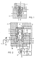
- a single-acting valve in cartridge design is shown. It is designed as a 2-way cartridge valve with the two line connections A, B. It is composed of a sleeve inserted into a bore 1 of a housing 2, a valve piston 4 slidably guided in the sleeve 3 with a valve seat 5 and a closing spring 6.
- the bore 1 is closed by a cover plate 7, in which a pilot line 8 is provided, which connects the interior of the valve piston 4 with a pilot valve or another control device (not shown).
- a narrow bore 9 is provided in the bottom of the valve piston 4, which connects the line connection A to the interior of the valve piston 4 and thus to the pilot valve or the control device.
- the closing spring 6 is a relatively weak spring which practically does not affect the opening process; it closes the valve in the absence of pressure.
- FIG. 1 From Fig. 1 it can be seen that this valve only at can respond to a pressure increase in line connection A.
- the line connection B is not connected to the pilot control (not shown), so that the valve cannot respond depending on the pressure in the line connection B. It is essential that in the valve according to FIG. 1 the surface of the valve piston 4 at the line connection A can be made practically the same size as the diameter of the valve piston 4 in the sleeve 3.
- the valve can always respond when there is a higher pressure in one of the two line connections A, B, a shuttle valve 10 and a pilot-controlled reversing valve 11 are provided.
- the line connection A is connected via a line 12 and the line connection B via a line 13 to the shuttle valve 10 and the reversing valve 11.
- the shuttle valve 10 can be designed, for example, as a check valve with two inlet lines 15, 16 and one outlet line 17.
- the shuttle valve 10 is shown in FIG. 2 for higher pressure in the feed line 15, as a result of which the valve ball is pressed against the feed line 16 and closes it, so that the feed line 15 is connected to the drain line 17, which opens into an annular space 18.
- the pilot line 8 goes from the annular space 18 to a pilot valve 19, which is only shown as a symbol.
- This valve can be designed, for example, as a spring-loaded valve cone that opens rests on a valve seat and blocks line 8. If the pressure exceeds a certain pressure defined by the spring, the valve opens, as a result of which the pressure in the annular space 18 is reduced, since the connecting lines 12, 13 to the line connections A, B are throttled in a suitable manner, for example by a throttle (not shown) are.
- cup-shaped valve piston 4 is connected at its free end to an annular piston 20 which forms two annular surfaces 21, 22.
- the inside diameter of the annular piston 20 can be equal to the outside diameter of the valve piston 4 and the area of the annular surfaces 21, 22 can be the same size.
- the annular surface 22 is connected directly to the line connection B via a line 23.
- the cover plate 7 is closed by a cover 23 which has a projecting pin 24 which forms the inner wall of the annular space 18 for the annular piston 20.
- the pilot-controlled shuttle valve 11 has two inlet lines 25, 26 and an outlet line 27, which is connected to the interior 28 of the valve piston 4.
- the function of the reversing valve is opposite to that of the shuttle valve 10, since the respectively higher pressure in one of the two inlet lines 25, 26 controls the double valve body in such a way that the inlet line with the lower pressure is connected to the outlet line 27.
- This means that the interior 28 is always connected to that of the two line connections A, B in which the lower pressure prevails, which is either equal to the atmospheric pressure or a few bar above this.
- annular space 18 is always connected to that of the two line connections A, B in which the higher pressure prevails.
- the shuttle valve 10 is brought into the position shown in FIG. 2, so that there is a connection between the inlet line 15 and the outlet line 17 and thus with the annular space 18. If the pressure in the line connection A now rises above the pressure set in the pilot control valve 19, this opens and causes the valve piston 4 to open, the pressure fluid flowing after the line connection B. If the greater pressure prevails in the line connection B, the shuttle valve 10 closes the inlet line 15 and connects the inlet line 16 to the outlet line 17 and to the annular space 18. At the same time, the double valve body 29 in the reversing valve 11 is brought into the opposite position as in FIG. ie the inlet line 26 is blocked and the inlet line 25 having the low pressure is connected to the outlet line 27 and to the interior 28 of the valve piston 4.
- the annular piston 18 represents only a small increase in the mass of the valve piston 4, since its overall height need not be significantly greater than the stroke of the valve piston 4. In addition, it is possible without difficulty to make the bottom surface of the valve piston 4 directed against the line connection A the same size as the two ring surfaces 21, 22, as a result of which a high sensitivity is achieved.
- the valve according to FIG. 2 has been described as a double-acting pressure relief valve.
- a valve makes it possible to protect two pressure sides, for example a hydrostatic circuit, with the same value, ie to limit them to the same pressure.
- the flow takes place either from line connection A to line connection B or vice versa.
- the pilot valve 19 on the valve described is replaced by a manually or automatically switching bypass valve, the valve can be used as an idle valve, which connects the two line connections A, B to one another almost without pressure.
Landscapes
- Engineering & Computer Science (AREA)
- General Engineering & Computer Science (AREA)
- Mechanical Engineering (AREA)
- Physics & Mathematics (AREA)
- Fluid Mechanics (AREA)
- General Physics & Mathematics (AREA)
- Automation & Control Theory (AREA)
- Fluid-Driven Valves (AREA)
- Safety Valves (AREA)
- Fluid-Pressure Circuits (AREA)
- Servomotors (AREA)
- Valves And Accessory Devices For Braking Systems (AREA)
Priority Applications (1)
| Application Number | Priority Date | Filing Date | Title |
|---|---|---|---|
| AT83104521T ATE27051T1 (de) | 1982-05-19 | 1983-05-07 | Vorgesteuertes druckbegrenzungsventil fuer unter druck stehende fluidleitungen. |
Applications Claiming Priority (2)
| Application Number | Priority Date | Filing Date | Title |
|---|---|---|---|
| CH3131/82A CH658895A5 (de) | 1982-05-19 | 1982-05-19 | Druckbegrenzungsventil fuer unter druck stehende fluidleitungen. |
| CH3131/82 | 1982-05-19 |
Publications (2)
| Publication Number | Publication Date |
|---|---|
| EP0094579A1 true EP0094579A1 (fr) | 1983-11-23 |
| EP0094579B1 EP0094579B1 (fr) | 1987-05-06 |
Family
ID=4249284
Family Applications (1)
| Application Number | Title | Priority Date | Filing Date |
|---|---|---|---|
| EP83104521A Expired EP0094579B1 (fr) | 1982-05-19 | 1983-05-07 | Soupape pilote de limitation de pression pour circuits de liquides sous pression |
Country Status (6)
| Country | Link |
|---|---|
| US (1) | US4531540A (fr) |
| EP (1) | EP0094579B1 (fr) |
| AT (1) | ATE27051T1 (fr) |
| CH (1) | CH658895A5 (fr) |
| DE (1) | DE3371401D1 (fr) |
| ZA (1) | ZA832349B (fr) |
Cited By (1)
| Publication number | Priority date | Publication date | Assignee | Title |
|---|---|---|---|---|
| FR2686679A1 (fr) * | 1992-01-28 | 1993-07-30 | Reglage Thermique Ste Alsacien | Dispositif de securite protegeant contre les surpressions d'un fluide confine dans une enceinte. |
Families Citing this family (6)
| Publication number | Priority date | Publication date | Assignee | Title |
|---|---|---|---|---|
| DE8817026U1 (de) * | 1988-01-13 | 1992-03-05 | Barth, Hans, 7801 Schallstadt | Druckregelventil |
| LU88384A1 (de) * | 1993-07-16 | 1995-02-01 | Hydrolux Sarl | 2-Wege-Einbauventil als Sitzventil |
| US7490625B1 (en) | 2001-04-23 | 2009-02-17 | John Leslie Johnson | Pilot valve manifold |
| EP1800007B1 (fr) * | 2004-09-20 | 2013-12-25 | Magna Powertrain Inc. | Pompe a pression de sortie selectionnable |
| CN101943188B (zh) * | 2010-04-29 | 2013-08-21 | 上海人豪液压技术有限公司 | 采用组合式法兰控制盖板的紧凑型二通插装阀 |
| DE102021134609A1 (de) * | 2021-12-23 | 2023-06-29 | Eto Magnetic Gmbh | Durchströmbarer hydraulischer Ventilschieber, bidirektionales Regelventil und Verfahren |
Citations (2)
| Publication number | Priority date | Publication date | Assignee | Title |
|---|---|---|---|---|
| DE1775178B2 (fr) * | 1968-07-13 | 1975-04-10 | G.L. Rexroth Gmbh, 8770 Lohr | |
| DE2527249A1 (de) * | 1974-06-21 | 1976-01-08 | Hoerbiger Fluidtechnik Kg | Druckregler fuer stroemende medien |
Family Cites Families (5)
| Publication number | Priority date | Publication date | Assignee | Title |
|---|---|---|---|---|
| US2612019A (en) * | 1949-01-03 | 1952-09-30 | Havilland Engine Co Ltd | Propellent injection system with safety valve to cut off fluid pressure supply |
| US3060951A (en) * | 1956-12-26 | 1962-10-30 | Alsacienne Constr Meca | Hydraulic regulating system |
| CH364671A (de) * | 1958-12-02 | 1962-09-30 | Von Roll Ag | Vorgesteuertes Sicherheitsventil |
| US3238966A (en) * | 1963-06-28 | 1966-03-08 | Charles N Howard | Fluid operated control valve and gas control system |
| US4000754A (en) * | 1974-06-11 | 1977-01-04 | Maxton Manufacturing Company | Automatic control valve for a fluid system |
-
1982
- 1982-05-19 CH CH3131/82A patent/CH658895A5/de not_active IP Right Cessation
-
1983
- 1983-03-31 ZA ZA832349A patent/ZA832349B/xx unknown
- 1983-05-07 AT AT83104521T patent/ATE27051T1/de not_active IP Right Cessation
- 1983-05-07 DE DE8383104521T patent/DE3371401D1/de not_active Expired
- 1983-05-07 EP EP83104521A patent/EP0094579B1/fr not_active Expired
- 1983-05-13 US US06/494,319 patent/US4531540A/en not_active Expired - Fee Related
Patent Citations (2)
| Publication number | Priority date | Publication date | Assignee | Title |
|---|---|---|---|---|
| DE1775178B2 (fr) * | 1968-07-13 | 1975-04-10 | G.L. Rexroth Gmbh, 8770 Lohr | |
| DE2527249A1 (de) * | 1974-06-21 | 1976-01-08 | Hoerbiger Fluidtechnik Kg | Druckregler fuer stroemende medien |
Cited By (1)
| Publication number | Priority date | Publication date | Assignee | Title |
|---|---|---|---|---|
| FR2686679A1 (fr) * | 1992-01-28 | 1993-07-30 | Reglage Thermique Ste Alsacien | Dispositif de securite protegeant contre les surpressions d'un fluide confine dans une enceinte. |
Also Published As
| Publication number | Publication date |
|---|---|
| ZA832349B (en) | 1983-12-28 |
| CH658895A5 (de) | 1986-12-15 |
| ATE27051T1 (de) | 1987-05-15 |
| DE3371401D1 (en) | 1987-06-11 |
| EP0094579B1 (fr) | 1987-05-06 |
| US4531540A (en) | 1985-07-30 |
Similar Documents
| Publication | Publication Date | Title |
|---|---|---|
| DE1576088A1 (de) | Schnellentlastungsventil fuer hydraulische Kraftzylinder | |
| DE1947678A1 (de) | Drucksteuerventil mit mehreren Abtastergliedern | |
| DE2126763A1 (de) | Hydraulik-Steuerventil | |
| DE69230948T2 (de) | Einhebelmischarmatur mit einer Vorrichtung zum Vermeiden von Wasserschlägen während des Hebelschliessvorganges | |
| EP0094579B1 (fr) | Soupape pilote de limitation de pression pour circuits de liquides sous pression | |
| DE2551489A1 (de) | Steuerventil in hydraulischen stromkreisen | |
| DE3341643A1 (de) | Vorgesteuertes druckentlastungs- und steuerventil | |
| DE2407177A1 (de) | Hochdruck-ausloeseventil | |
| DE1006685B (de) | Einrichtung zur Regelung des Druckes innerhalb enger Grenzen in einer hydraulischen Anlage und/oder einem Speicher | |
| DE2240012C3 (de) | Steuereinrichtung für hydrostatische Hilfskraftlenkungen o.dgl. | |
| DE3006530A1 (de) | Hydraulisches blockier- oder halteventil | |
| DE3243182C2 (fr) | ||
| DE1103098B (de) | Mehrzwecksteuerventil | |
| DE2932523C2 (de) | Hydraulisch entsperrbares Sitzventil | |
| DE2536784C3 (de) | Hydraulische Ventileinrichtung zur Wegesteuerung des Arbeitsdruckmittels für einen hydraulischen Servomotor | |
| DE2307285A1 (de) | Ventil, insbesondere entlueftungsventil | |
| DE1222754B (de) | Rohrbruchventil | |
| DE2034214A1 (de) | Steuervorrichtung fur einen hydrauli sehen Arbeitskreis | |
| DE1101887B (de) | Hydraulische Steuervorrichtung | |
| DE2833971A1 (de) | Leitungsbruchsicherungs-vorrichtung | |
| DE936130C (de) | Einrichtung zur druckabhaengigen Steuerung eines hydraulischen Systems | |
| DE1775602B1 (de) | Halte und loesevorrichtung fuer steuerschieber hydraulischer wegeventile | |
| DE2602923C3 (de) | Bremsventil | |
| DE3136535C2 (fr) | ||
| DE1104785B (de) | Hilfsgesteuerte UEberdruck-Entlastungs-vorrichtung fuer hydraulische Anlagen |
Legal Events
| Date | Code | Title | Description |
|---|---|---|---|
| PUAI | Public reference made under article 153(3) epc to a published international application that has entered the european phase |
Free format text: ORIGINAL CODE: 0009012 |
|
| AK | Designated contracting states |
Designated state(s): AT DE FR GB |
|
| RAP1 | Party data changed (applicant data changed or rights of an application transferred) |
Owner name: VON ROLL - HYDRAULIK A.G. |
|
| 17P | Request for examination filed |
Effective date: 19840220 |
|
| GRAA | (expected) grant |
Free format text: ORIGINAL CODE: 0009210 |
|
| AK | Designated contracting states |
Kind code of ref document: B1 Designated state(s): AT DE FR GB |
|
| REF | Corresponds to: |
Ref document number: 27051 Country of ref document: AT Date of ref document: 19870515 Kind code of ref document: T |
|
| REF | Corresponds to: |
Ref document number: 3371401 Country of ref document: DE Date of ref document: 19870611 |
|
| ET | Fr: translation filed | ||
| PLBE | No opposition filed within time limit |
Free format text: ORIGINAL CODE: 0009261 |
|
| STAA | Information on the status of an ep patent application or granted ep patent |
Free format text: STATUS: NO OPPOSITION FILED WITHIN TIME LIMIT |
|
| 26N | No opposition filed | ||
| PGFP | Annual fee paid to national office [announced via postgrant information from national office to epo] |
Ref country code: GB Payment date: 20010412 Year of fee payment: 19 |
|
| PGFP | Annual fee paid to national office [announced via postgrant information from national office to epo] |
Ref country code: AT Payment date: 20010427 Year of fee payment: 19 |
|
| PGFP | Annual fee paid to national office [announced via postgrant information from national office to epo] |
Ref country code: FR Payment date: 20010507 Year of fee payment: 19 |
|
| PGFP | Annual fee paid to national office [announced via postgrant information from national office to epo] |
Ref country code: DE Payment date: 20010509 Year of fee payment: 19 |
|
| REG | Reference to a national code |
Ref country code: GB Ref legal event code: IF02 |
|
| PG25 | Lapsed in a contracting state [announced via postgrant information from national office to epo] |
Ref country code: GB Free format text: LAPSE BECAUSE OF NON-PAYMENT OF DUE FEES Effective date: 20020507 Ref country code: AT Free format text: LAPSE BECAUSE OF NON-PAYMENT OF DUE FEES Effective date: 20020507 |
|
| PG25 | Lapsed in a contracting state [announced via postgrant information from national office to epo] |
Ref country code: DE Free format text: LAPSE BECAUSE OF NON-PAYMENT OF DUE FEES Effective date: 20021203 |
|
| GBPC | Gb: european patent ceased through non-payment of renewal fee |
Effective date: 20020507 |
|
| PG25 | Lapsed in a contracting state [announced via postgrant information from national office to epo] |
Ref country code: FR Free format text: LAPSE BECAUSE OF NON-PAYMENT OF DUE FEES Effective date: 20030131 |
|
| REG | Reference to a national code |
Ref country code: FR Ref legal event code: ST |