EP0094582A2 - Dispositif pour suspendre une personne par les jambes - Google Patents
Dispositif pour suspendre une personne par les jambes Download PDFInfo
- Publication number
- EP0094582A2 EP0094582A2 EP83104531A EP83104531A EP0094582A2 EP 0094582 A2 EP0094582 A2 EP 0094582A2 EP 83104531 A EP83104531 A EP 83104531A EP 83104531 A EP83104531 A EP 83104531A EP 0094582 A2 EP0094582 A2 EP 0094582A2
- Authority
- EP
- European Patent Office
- Prior art keywords
- outer jacket
- ankle
- area
- hook
- lining
- Prior art date
- Legal status (The legal status is an assumption and is not a legal conclusion. Google has not performed a legal analysis and makes no representation as to the accuracy of the status listed.)
- Withdrawn
Links
- 210000003423 ankle Anatomy 0.000 claims abstract description 40
- 210000002414 leg Anatomy 0.000 claims abstract description 39
- 239000000725 suspension Substances 0.000 claims abstract description 34
- 210000002683 foot Anatomy 0.000 claims abstract description 18
- 244000309466 calf Species 0.000 claims abstract description 16
- 210000003127 knee Anatomy 0.000 claims abstract description 6
- 239000006260 foam Substances 0.000 claims description 5
- 239000007787 solid Substances 0.000 claims description 2
- 101100390736 Danio rerio fign gene Proteins 0.000 description 6
- 101100390738 Mus musculus Fign gene Proteins 0.000 description 6
- 230000006978 adaptation Effects 0.000 description 5
- 239000000463 material Substances 0.000 description 5
- 210000003205 muscle Anatomy 0.000 description 4
- 238000005452 bending Methods 0.000 description 3
- 210000003108 foot joint Anatomy 0.000 description 3
- 230000007704 transition Effects 0.000 description 3
- 230000002411 adverse Effects 0.000 description 2
- 238000004519 manufacturing process Methods 0.000 description 2
- 210000003489 abdominal muscle Anatomy 0.000 description 1
- 229910052782 aluminium Inorganic materials 0.000 description 1
- XAGFODPZIPBFFR-UHFFFAOYSA-N aluminium Chemical compound [Al] XAGFODPZIPBFFR-UHFFFAOYSA-N 0.000 description 1
- 210000000544 articulatio talocruralis Anatomy 0.000 description 1
- 230000008878 coupling Effects 0.000 description 1
- 238000010168 coupling process Methods 0.000 description 1
- 238000005859 coupling reaction Methods 0.000 description 1
- 238000006073 displacement reaction Methods 0.000 description 1
- 210000003414 extremity Anatomy 0.000 description 1
- 238000009434 installation Methods 0.000 description 1
- 229910052751 metal Inorganic materials 0.000 description 1
- 239000002184 metal Substances 0.000 description 1
- 230000002787 reinforcement Effects 0.000 description 1
- 125000006850 spacer group Chemical group 0.000 description 1
- 230000003068 static effect Effects 0.000 description 1
- 230000001225 therapeutic effect Effects 0.000 description 1
- 210000000689 upper leg Anatomy 0.000 description 1
- XLYOFNOQVPJJNP-UHFFFAOYSA-N water Substances O XLYOFNOQVPJJNP-UHFFFAOYSA-N 0.000 description 1
Images


Classifications
-
- A—HUMAN NECESSITIES
- A61—MEDICAL OR VETERINARY SCIENCE; HYGIENE
- A61H—PHYSICAL THERAPY APPARATUS, e.g. DEVICES FOR LOCATING OR STIMULATING REFLEX POINTS IN THE BODY; ARTIFICIAL RESPIRATION; MASSAGE; BATHING DEVICES FOR SPECIAL THERAPEUTIC OR HYGIENIC PURPOSES OR SPECIFIC PARTS OF THE BODY
- A61H1/00—Apparatus for passive exercising; Vibrating apparatus; Chiropractic devices, e.g. body impacting devices, external devices for briefly extending or aligning unbroken bones
- A61H1/02—Stretching or bending or torsioning apparatus for exercising
- A61H1/0218—Drawing-out devices
-
- A—HUMAN NECESSITIES
- A61—MEDICAL OR VETERINARY SCIENCE; HYGIENE
- A61H—PHYSICAL THERAPY APPARATUS, e.g. DEVICES FOR LOCATING OR STIMULATING REFLEX POINTS IN THE BODY; ARTIFICIAL RESPIRATION; MASSAGE; BATHING DEVICES FOR SPECIAL THERAPEUTIC OR HYGIENIC PURPOSES OR SPECIFIC PARTS OF THE BODY
- A61H2201/00—Characteristics of apparatus not provided for in the preceding codes
- A61H2201/16—Physical interface with patient
- A61H2201/1602—Physical interface with patient kind of interface, e.g. head rest, knee support or lumbar support
- A61H2201/164—Feet or leg, e.g. pedal
- A61H2201/1642—Holding means therefor
Definitions
- the invention relates to a device for hanging a person on the legs with a solid outer jacket comprising the foot joint area at least on its front side and with a locking device for holding the hanging device in the area of the ankle joint and with a device for attaching to a support rod, a ceiling hook
- a device of this type has already become known, for example, from US Pat. No. 3,380,447. In this device, it is criticized that it encloses only the foot g élénk od, and this in connection with the manner of attachment of the device to attach to a support rod. Dcl. to an undesirable load on the leg and ankle leads. In particular, torsional or torsional loads can be determined.
- the object of the invention is therefore to develop the device of the type mentioned in such a way that the load on the leg, in particular the lower leg and also the ankle of the suspended person, is eliminated. but at least is reduced.
- the device is designed according to the preamble of claim 1 according to the characterizing part of this claim. Due to the arrangement of the hardening loop, approximately in the area of a plane through the longitudinal central axis of the device, the direction of force from the weight load extends approximately in the longitudinal central axis of the leg - such a device is of course attached to each leg - so that on the whole it is only seen is subjected to a tensile load. Bending, torsional and torsional stresses are at least largely eliminated, and the person can be hung up with straight legs. At least as regards the design of the device and the suspension as such, angling, for example in the knee area, is not necessary.
- this device is a device which is used for the therapeutic treatment of should serve suspended person.
- the primary aim here is to relieve the spine, with the intervertebral discs being relieved during the period of suspension so that they can move back into their correct position, for example in the event of a small lateral displacement.
- this also applies to slightly offset vertebrae.
- the device is also used in the field of sports for training purposes because it enables sporting exercises to be carried out with the spine unloaded. With this device, for example, the abdominal muscles, the muscles of the thighs and other muscle areas can be strengthened. Both in the medical and in the sports field, it is essential that the relief of the spine is not accompanied by an adverse load on the legs, in particular the lower leg and the joint areas.
- the rear support member is designed as a loop-shaped, stiff bracket which extends from the hook or the like in the direction of the knee and whose end remote from the hook encompasses the leg on the back of the calf area.
- Decisive for the relief is primarily the part of the bracket furthest away from the hook, which surrounds the calf area, for example, in a semicircle.
- the remaining part of this loop-shaped bracket represents a largely rigid spacer for holding this rear bracket part.
- a further embodiment of the invention consists in that at least the arcuate part of the bracket lying away from the hook is provided with soft elastic padding. It increases comfort and enables better adaptation to the respective calf shape. At the same time, the surface pressure in this area is reduced. The latter would also be possible with a pressure plate, but you would have to adapt it to the Also pad the calf shape.
- the proposed training has manufacturing advantages.
- the soft elastic padding of the rigid pipe section is formed by a pipe section made of foam, rubber or the like. It can be easily pushed over the bracket, which is also conveniently made from a tube.
- an unslit piece of pipe made of foam should be preferred because it is more robust and dimensionally stable in the long run.
- the rigid stirrup is detachably connected to the outer jacket in a very advantageous manner, this simplifies the assembly of the upholstery, in particular if it is an unslit piece of pipe made of foam.
- the device for shipping can be made more compact.
- the attachment of the bracket by the user is absolutely problem-free if the bracket and the outer jacket are releasably held together in a further development of the invention via a push-button-like connection. It is irrelevant whether the closure parts of the push-button-type connection are attached directly to the outer jacket or to the two bow ends or to intermediate elements which are firmly connected to the outer jacket on the one hand and / or the bow ends on the other hand and possibly simplify production bring. This can also egg ne more stable training can be achieved in this fastening area.
- a device with a resilient lining of the outer jacket is that the lining projects beyond the outer jacket both at its end facing the foot and the calf. This prevents the rigid outer sheath from being pressed into the foot or leg, especially when attaching and detaching, but also during certain gymnastic exercises.
- the extent to which the spring-elastic lining protrudes depends on the special shape and length of the outer jacket, seen in the longitudinal direction of the leg.
- the elastic properties of this lining must also be selected in accordance with the elasticity of the outer jacket. For the protection of the ankle, it is advantageous if the total elasticity of the outer jacket and lining is not too great.
- a further embodiment of the invention is characterized by a spring-elastic lining of the rear support member, which projects beyond the latter at least at its end facing the hollow of the knee.
- the rear support member is also overhanged by the lining along its longitudinal edges, in order to avoid pressure points on the calf or lower leg.
- a particularly preferred embodiment of the invention provides that the resilient lining of the outer jacket and the rear support member are made in one piece, in particular at least largely encloses the ankle area. As a rule, however, it will be best if the ankle area is completely enclosed.
- the hook is made in one piece with a stiffening plate which is firmly connected to the outer jacket, in particular riveted to it.
- the weight of the suspended body is transferred from the hook to the stiffening plate and from the latter via the fastening elements to the outer jacket.
- all the parts mentioned must be worked very solidly and held together perfectly. Since only half the weight of the person is given up on each device, it is sufficient even for tall and heavy people if the stiffening plate is fastened, for example, with four strong rivets.
- the stiffening plate is expediently placed on the outside of the surface of the outer jacket assigned to the front of the ankle region, an additional stiffening plate being located on the inside of this region, which has a receptacle for the two ends of the loop-shaped stiff strap.
- the receptacle is advantageously located outside the outer casing, ie in the position of use below the outer casing. This gives them the opportunity to make them stable and big enough, which makes them smart fen-shaped rigid bracket can also be generously dimensioned at its fastening end, or no reduction in cross section is required there. Also with regard to the releasable connection, it is advantageous if this additional stiffening plate is led outwards in this way and its external approach is chosen large enough.
- the two ends of the suspension loop of the embodiment of the invention described at the outset are designed in a very advantageous manner in a ring-like manner and are each suspended in a support bolt of the outer jacket, each support bolt preferably having a thickened head. The latter prevents the hanging up eye from being unintentionally removed.
- the support bolts can be attached or molded to a further inner or outer support plate, which can be riveted to the outer jacket in the same way as the support plate with the U-shaped hook.
- the resilient lining of the outer jacket is designed in the manner of a longitudinally slotted sleeve, the sleeve ends tapering in a wedge shape and overlap at least in the position of use. That is, in the starting position, the lining can either take a U-shape, which makes it easier to put on this device, or it can be pre-shaped so that the ends have to be spread apart to put on the device. In the first case, the overlap takes place only in the use position, while in the second case, possibly to a lesser extent, it overlaps even before use Condition of the device can be present.
- the length of the wedges in seen the sleeve depending on the thickness and the selected material can be chosen according to needs.
- the resilient lining projects beyond the outer casing at least with its wedge-shaped ends in the circumferential direction. If the outer jacket only encompasses the foot at about 180 °, then the second 180 °, that is to say the rest of the ankle area, is covered exclusively by the spring-elastic lining. For example, it can be pressed onto this foot joint area with the aid of a locking device designed in a special way, wherein this locking device can perform a function similar to that of the outer jacket. In this case it is expedient if the overlap of the resilient lining is comparatively long and extends approximately over this second 180 ° range. The latter is incidentally the back of the leg arranges because the suspension hook is known to be assigned to the front of the leg or ankle and is attached to the outer jacket.
- the resilient lining of the outer jacket is optionally formed, including the resilient lining of the rear support member, in the manner of an inner boot, a ski boot consisting of an inner and outer boot.
- the inner drawer consists of a sheath filled with a special material, whereby this material deforms under the influence of heat and thereby achieves a particularly clean adaptation to the respective ankle shape.
- the lining surrounds the toe region.
- it is entirely possible that the lining projects beyond the outer jacket in such a way that the sole of the foot is also encompassed at least in its central region.
- the outer jacket is designed in the manner of a longitudinally slotted sleeve, the sleeve ends overlapping at least in the position of use.
- the outer jacket can also be shaped such that it assumes an approximately U-shaped shape in the starting position, in order to enable easier attachment to the ankle.
- which shape you choose in detail may also depend on the choice of material.
- the closed sleeve has the advantage that no or only a few additional bending stresses are applied in the position of use.
- the sleeve ends of the outer jacket advantageously run in a wedge shape.
- the explanations for elastic lining apply analogously here.
- the wedge-shaped and overlapping finds allow adaptation to quite different ankle sizes, in contrast to the prior art, where the ends of the outer jacket butt butt against one another, so that adaptation to a weaker ankle is not possible.
- the overlap region of the sleeve ends of at least the outer jacket is roughly assigned to the front of the ankle.
- the latter and possibly also the reinforcement plate are located in the central region of the front of the foot, which is why the overlap region of the sleeve ends of the outer jacket must lie to the side thereof.
- the overlap area of the outer jacket can be assigned directly to the middle part of the front of the ankle.
- the fastening belt holds both the longitudinally slotted outer jacket and its spring elastic together. Lining and a tight attachment of the suspension device to differently strong ankles. On the other hand, you can design this locking device so that it can be opened and locked quickly.
- toggle-like or buckle-like locks as are known for ski boots, have proven themselves.
- the fastening belt consists of hard but elastic plastic and that the belt-like element of the buckle-like lock is fastened and adjustable at one end.
- the "coupling" of the buckle-like lock to this free fastening belt end can advantageously be carried out by means of a latching device which enables the necessary span length to be tapped off in small steps.
- the outer jacket is advantageously made of strong but resilient plastic, while the bracket is advantageously made of metal, for example aluminum.
- the resilient lining lends itself in particular to a foam rubber-like plastic.
- the thickness of the resilient lining is in the range of 1 to 2 cm, while a thickness of the order of about 1/2 cm is sufficient for the outer jacket.
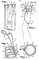
- the suspension device has an outer jacket 12 with a stiffening plate 14 which is held on a base plate 18 with the aid of fastening elements 16, for example rivets.
- the outer jacket 12 is designed in such a way that it fits snugly in the area of the ankle, ie at the transition from the leg to the foot of a person. If the device is opened before being placed on the leg, it has a substantially U-shaped shape, whereby the stiffening plate 14 is located on the U crossbar.
- a resilient lining 20 is attached, which is slightly wider than the outer jacket, so that edge strips 22 and 24 protrude above and below the outer jacket.
- Two strap-like fastening belts 26 are fastened with their fastening end 28 to the outer jacket 12 and their other, free end is designated by 30. It stands, as shown in Fig. 5, in the longitudinal direction over the outer jacket and is held in the use position in a buckle-like lock 32 which is attached to the other U-leg of the outer jacket.
- a U-shaped hook 34 is fastened with its one U-leg 36 to the stiffening plate 1u, while its other leg has a preferably spherical end 38, this other leg being removed from the side of the suspension device which is the foot 40 of a person to be suspended 42 has turned.
- a loop-shaped bracket 44 is attached with its ends 46 to the stiffening plate 14 on both sides of the leg of the U-shaped hook 34 located there. The bracket is spread out from the outer jacket 12 and extends in such a direction that it rests on the rear side of the leg 48 of the person to be hung.
- a soft, resilient padding 50 is attached to the location of the bracket 44 which is in contact with the leg or calf.
- the suspension device 10 which is preferably preformed such that the outer jacket 12 and the federela
- the static liner 20 normally assume a closed position, as shown in FIGS. 3 and 4 show, in the area of the ankle at the transition from the leg to the foot, the stiffening plate 14 being assigned to the front of the leg.
- the outer jacket and the elastic lining overlap automatically on the leg and the free ends 30 of the fastening belts 26 are then inserted into their lock 32 and subjected to; whereby the suspension device is securely held on the person to be suspended.
- Another suspension device is then placed on the other ankle, and then the hooks 34 are hung, for example on a bar 52 of the bar or the like mentioned, whereby the person is suspended in the opposite position for treatment or for exercise purposes. Because the hooks are placed on the front of the leg and the loop-shaped tabs 44 attack on the back of the leg, this suspension device results in a comfortable position that avoids bending or rotating the suspended load, that is, keeps adverse loads on the leg and ankle away .
- the outer jacket 1? and the resilient lining 20 in contrast to the embodiment according to FIGS. 1 to 4 are not shaped in such a way that their free ends overlap one another in the initial state, rather the loose suspension device assumes a U-like shape before being placed on the ankle of a person to be suspended.
- the embodiment according to FIG. 4 can also be brought into the shape according to FIG. 5 by resiliently pulling its ends apart. If the embodiment according to FIG.
- FIGS. 6 to 10 A further embodiment of the invention can be seen in FIGS. 6 to 10 and is designated 10a.
- the outer jacket 12a For fastening in the area of the person's ankle, the outer jacket 12a has a resilient lining 20a which is fastened to its inside, the lining being in turn wider than the outer jacket, so that an upper and lower edge strip 22a and 24a protrude.
- a pair of fastening straps 26a are mounted with their fastening end 28a on the outer jacket and the other ends 30a can be inserted into a buckle-like lock 32a and detachably held therein.
- the locks 32a are held on the outer casing 12.
- a suspension means for this suspension device is formed by two support bolts 54. They are mounted on opposite sides of the outer casing 12 and placed in such a way that they assume a central position with respect to the foot of the person.
- the suspension device 12a is shaped in such a way that it fits to the transition area from the leg to the foot, that is to say approximately the foot joint area.
- the outer jacket 12 and the lining 20 are preferably preformed again in such a way that their free ends overlap in the loose state and thereby encompass the joint area. In this case it is necessary to open the hanger before putting it on.
- a variation of this embodiment is that it takes on a substantially U-shaped shape before being tightened, as shown in Fig. 10 of the drawing.
- the suspension device is preferably shaped so that the U-center piece is assigned to the back of the person, as the drawing shows, but this embodiment is not limited to this, rather the suspension device can also be shaped and designed such that the U-center piece on the front of the person, i.e. assigned to the shin. In both cases, however, the support bolts 54 are located opposite each other on the inside and outside of the pure of the person to be hung.
- the hanging device 10a is placed in the ankle area of the person.
- the ends of the outer casing 12a and the elastic lining 20a are folded over and the fastening straps 26a are inserted and tightened in their lock 32a.
- the support bolts 54 are now used to hold the device on the stretching rod 52 or the like, whereby the person for treatment or the like in an inverted position, ie upside down is hung.
- a hanging loop 56 is used, which has an eyelet 58 at each end.
- An eyelet is slid over one of the support bolts 54, which is preferably provided with a thickened head, and, after the suspension loop has been placed over the stretching rod 52, the other eyelet is also suspended in the support bolts on the other side of the device.
- this hanging device is used in the same way and the person is thus able to be hung upside down. It is expressly pointed out that this embodiment is not limited to being attached to a stretching rod 52 in the manner described above, but that other suitable means can also be used for this purpose, such as a stiff, not shown hanging means with an eyelet for Attachment to the support bolt, and a hook at its end for attaching to the horizontal bar, although this embodiment should not be regarded as a limitation.
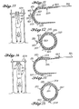
- 11 and 12 show a further embodiment of the suspension device, which is designated by 10b.
- This is a variation of the suspension device shown in FIGS. 1 to 4 or 5.
- This embodiment in turn has an outer jacket 12b, the leg lengths of which are limited.
- the resilient lining 20b which serves for cushioning, is fastened to the inside of the outer jacket and its ends taper in a wedge shape in order to facilitate the folding over when fastening this device.
- the fastening straps 26b are again held around one end 28b on the outer shell 12, and a buckle-like lock 32b is located on the opposite side of the outer shell.
- Fs receives the end 30b of the associated fastening straps, whereby the ends of the device are held together in an adjustable manner.
- a U-shaped hook 34b is fastened to the end 36b of the outer jacket 12, specifically to the U center piece.
- the ends 46b of a loop-shaped bracket 44b are fastened to the outer jacket 12 along the one hook leg.
- the loop-shaped bracket extends in such a direction that it runs along the leg of the person to be hung.
- the liner 20 is preferably preformed such that its legs overlap as shown in FIG. 12. However, this does not necessarily have to be the case and another variant can consist of it. that the device takes on a substantially U-shaped shape before application, as shown in FIG. 11.
- FIGS. 14 and 15 A further variant of the invention is shown in FIGS. 14 and 15.
- This suspension device is designated 10c.
- This device has an outer jacket 12c with limbs of limited length.
- the lining 20 is in turn attached to the inside of the outer jacket and its ends are again wedge-shaped in order to facilitate the overlap when applying and fastening this device.
- the fastening straps 26c are fastened with their one ends 28c to the outer casing and locks 32c are located on the opposite side of the outer jacket. They take up the ends 30c of each fastening strap, whereby the two ends of the suspension device are connected to one another in an adjustable manner. Furthermore, a pair of support bolts are attached to the outer jacket.
- the lining 20c is preferably preformed again such that its leg ends overlap as shown in FIG. 15.
- the suspension device is essentially U-shaped before installation; as shown in FIG. 14.
Landscapes
- Health & Medical Sciences (AREA)
- Animal Behavior & Ethology (AREA)
- Pain & Pain Management (AREA)
- Physical Education & Sports Medicine (AREA)
- Rehabilitation Therapy (AREA)
- Life Sciences & Earth Sciences (AREA)
- Epidemiology (AREA)
- General Health & Medical Sciences (AREA)
- Public Health (AREA)
- Veterinary Medicine (AREA)
- Orthopedics, Nursing, And Contraception (AREA)
- Finger-Pressure Massage (AREA)
- Medicines Containing Material From Animals Or Micro-Organisms (AREA)
- Footwear And Its Accessory, Manufacturing Method And Apparatuses (AREA)
Applications Claiming Priority (2)
| Application Number | Priority Date | Filing Date | Title |
|---|---|---|---|
| US379106 | 1982-05-17 | ||
| US06/379,106 US4515152A (en) | 1982-05-17 | 1982-05-17 | Load centering boot for inverse suspension |
Publications (2)
| Publication Number | Publication Date |
|---|---|
| EP0094582A2 true EP0094582A2 (fr) | 1983-11-23 |
| EP0094582A3 EP0094582A3 (fr) | 1984-03-07 |
Family
ID=23495853
Family Applications (1)
| Application Number | Title | Priority Date | Filing Date |
|---|---|---|---|
| EP83104531A Withdrawn EP0094582A3 (fr) | 1982-05-17 | 1983-05-07 | Dispositif pour suspendre une personne par les jambes |
Country Status (4)
| Country | Link |
|---|---|
| US (1) | US4515152A (fr) |
| EP (1) | EP0094582A3 (fr) |
| JP (1) | JPS58209364A (fr) |
| AU (1) | AU1448583A (fr) |
Cited By (3)
| Publication number | Priority date | Publication date | Assignee | Title |
|---|---|---|---|---|
| RU2271792C2 (ru) * | 2004-06-03 | 2006-03-20 | Василий Борисович Бартов | Устройство для тренировки мышц и вытягивания позвоночника |
| CN107648011A (zh) * | 2017-10-31 | 2018-02-02 | 大连大学 | 一种老年人用固定式外骨骼康复训练机械装置 |
| WO2019149317A1 (fr) * | 2018-01-31 | 2019-08-08 | ReActive Robotics GmbH | Système de décharge pour la décharge au moins partielle du poids du corps d'une personne |
Families Citing this family (16)
| Publication number | Priority date | Publication date | Assignee | Title |
|---|---|---|---|---|
| JPS61185453U (fr) * | 1985-05-10 | 1986-11-19 | ||
| US5003967A (en) * | 1988-03-25 | 1991-04-02 | Mcconnell Bernard E | Hand traction wrap |
| US5419756A (en) * | 1988-03-25 | 1995-05-30 | Mcconnell Orthopedic Mfg. Co., Inc. | Arm traction device and method of using same |
| USD334623S (en) | 1990-02-01 | 1993-04-06 | Spinal Designs International, Inc. | Traction unit for removing loading from the back |
| US5195949A (en) * | 1990-02-01 | 1993-03-23 | Spinal Designs International, Inc. | Traction device |
| US5105803A (en) * | 1990-02-28 | 1992-04-21 | Spinal Designs International, Inc. | Gravity traction device with a base support |
| US5169364A (en) * | 1991-06-06 | 1992-12-08 | Donaldson Keith D | Weight attachable leg exercise device |
| RU2146162C1 (ru) * | 1999-05-28 | 2000-03-10 | Палько Анатолий Степанович | Манжета для соединения тренирующегося с тренажером |
| US6814691B1 (en) * | 2002-09-09 | 2004-11-09 | Chung Jen Kuo | Secured mount for a body inversion exerciser |
| US7081073B1 (en) * | 2004-12-07 | 2006-07-25 | Roger C. Teeter | Foot retaining device for inversion exerciser |
| USD631109S1 (en) * | 2009-05-14 | 2011-01-18 | Expectations, LLC | Foot pad for tilting inversion exerciser |
| US8012073B2 (en) | 2009-12-22 | 2011-09-06 | Michael Charles Barnett | Fitness machine with automated variable resistance |
| US9839804B2 (en) * | 2015-04-17 | 2017-12-12 | Timothy R. Werner | Pole vault swing-up rack |
| RU210817U1 (ru) * | 2021-04-28 | 2022-05-05 | Борис Эргардович Филимонов | Фиксирующая манжета для тренажера |
| US12207704B2 (en) * | 2022-10-03 | 2025-01-28 | Nathan Bertrand | Footwear for inversion exercises |
| PL449238A1 (pl) * | 2024-07-15 | 2026-01-19 | Jacek Bartoszuk | Przyrząd treningowy do wykonywania pozycji odwróconej |
Family Cites Families (9)
| Publication number | Priority date | Publication date | Assignee | Title |
|---|---|---|---|---|
| US2696208A (en) * | 1952-02-04 | 1954-12-07 | Falls Herbert Pitman | Surgical traction boot |
| US2723663A (en) * | 1954-04-23 | 1955-11-15 | Ralph E Davis | Traction cuff |
| US2973757A (en) * | 1957-11-21 | 1961-03-07 | Katthoefer Eric | Therapeutic aid |
| US2952459A (en) * | 1959-04-13 | 1960-09-13 | Morris R Moffitt | Leg exercising device |
| US2969790A (en) * | 1960-02-12 | 1961-01-31 | Reddig Phyllis | Surgical traction boot |
| US3380447A (en) * | 1965-10-19 | 1968-04-30 | Robert M. Martin | Ankle device for supporting an individual in an inverted position |
| DE2063468C3 (de) * | 1970-12-23 | 1978-07-20 | Peter 6909 Walldorf Mandel | Übungsgerät zur Stärkung der Muskulatur |
| US3875923A (en) * | 1974-02-27 | 1975-04-08 | Marvin H Horel | Slingshot with arm brace and range indicating indicia |
| JPS54179270U (fr) * | 1978-06-07 | 1979-12-18 |
-
1982
- 1982-05-17 US US06/379,106 patent/US4515152A/en not_active Expired - Lifetime
-
1983
- 1983-05-04 JP JP58077677A patent/JPS58209364A/ja active Pending
- 1983-05-07 EP EP83104531A patent/EP0094582A3/fr not_active Withdrawn
- 1983-05-12 AU AU14485/83A patent/AU1448583A/en not_active Abandoned
Cited By (4)
| Publication number | Priority date | Publication date | Assignee | Title |
|---|---|---|---|---|
| RU2271792C2 (ru) * | 2004-06-03 | 2006-03-20 | Василий Борисович Бартов | Устройство для тренировки мышц и вытягивания позвоночника |
| CN107648011A (zh) * | 2017-10-31 | 2018-02-02 | 大连大学 | 一种老年人用固定式外骨骼康复训练机械装置 |
| WO2019149317A1 (fr) * | 2018-01-31 | 2019-08-08 | ReActive Robotics GmbH | Système de décharge pour la décharge au moins partielle du poids du corps d'une personne |
| US11357693B2 (en) | 2018-01-31 | 2022-06-14 | ReActive Robotics GmbH | Relief system for at least partially relieving the body weight of a person |
Also Published As
| Publication number | Publication date |
|---|---|
| AU1448583A (en) | 1983-11-24 |
| EP0094582A3 (fr) | 1984-03-07 |
| JPS58209364A (ja) | 1983-12-06 |
| US4515152A (en) | 1985-05-07 |
Similar Documents
| Publication | Publication Date | Title |
|---|---|---|
| DE69000628T2 (de) | Orthese zur dreidimensionalen dynamischen rueckbildung einer skoliose. | |
| DE69002093T2 (de) | Orthopädische vorrichtung für gehbehinderte. | |
| DE2733205A1 (de) | Orthopaedische apparate, um gelaehmten das aufrechte stehen zu ermoeglichen | |
| DE2905388A1 (de) | Verbindungsvorrichtung, insbesondere fuer zwei skilaeufer | |
| EP0270661B1 (fr) | Dispositif orthopedique | |
| EP2858606B1 (fr) | Orthèse | |
| DE2921015A1 (de) | Orthopaedische vorrichtung | |
| DE2724586A1 (de) | Orthopaedische schiene zur stuetzung des kniegelenkes | |
| DE102011054094A1 (de) | Trainingsgerät | |
| DE60031805T2 (de) | Stützvorrichtung zum Abfangen des Körpergewichts und Trainingshilfe | |
| DE29719490U1 (de) | Hilfselement für Krücken | |
| WO1987006820A1 (fr) | Dispositif pour le maintien du genou, destine en particulier aux skieurs | |
| DE102015000783A1 (de) | Knöchelorthese | |
| EP3127513B1 (fr) | Systeme de traitement orthopedique de lesions et/ou de deformations de la jambe et/ou de la cheville | |
| DE2833482C2 (de) | Als Gehhilfe ausgebildete Stützprothese | |
| DE102004009315A1 (de) | Vorrichtung zur Entlastung des Rückens | |
| DE102014208717A1 (de) | Trainingsgerät | |
| DE202018102324U1 (de) | Oberlippenbremse für Pferde im Klammerstil | |
| DE202011103635U1 (de) | Gehhilfe | |
| DE2063468C3 (de) | Übungsgerät zur Stärkung der Muskulatur | |
| DE8313567U1 (de) | Vorrichtung zum Aufhängen einer Person an den Beinen | |
| DE20020135U1 (de) | Trainingseinrichtung zur Erzielung einer Penisverlängerung und/oder Penisstimulierung | |
| DE102010038699A1 (de) | Tragevorrichtung zum Tragen von Lasten | |
| DE102009009681B3 (de) | Orthopädische Vorrichtung | |
| DE10305131A1 (de) | Stützfeder |
Legal Events
| Date | Code | Title | Description |
|---|---|---|---|
| PUAI | Public reference made under article 153(3) epc to a published international application that has entered the european phase |
Free format text: ORIGINAL CODE: 0009012 |
|
| AK | Designated contracting states |
Designated state(s): AT CH DE FR GB IT LI NL SE |
|
| PUAL | Search report despatched |
Free format text: ORIGINAL CODE: 0009013 |
|
| AK | Designated contracting states |
Designated state(s): AT CH DE FR GB IT LI NL SE |
|
| STAA | Information on the status of an ep patent application or granted ep patent |
Free format text: STATUS: THE APPLICATION IS DEEMED TO BE WITHDRAWN |
|
| 18D | Application deemed to be withdrawn |
Effective date: 19850401 |
|
| RIN1 | Information on inventor provided before grant (corrected) |
Inventor name: TEETER, ROGER CHARLES |