EP0094628B1 - Schiebetor - Google Patents
Schiebetor Download PDFInfo
- Publication number
- EP0094628B1 EP0094628B1 EP83104690A EP83104690A EP0094628B1 EP 0094628 B1 EP0094628 B1 EP 0094628B1 EP 83104690 A EP83104690 A EP 83104690A EP 83104690 A EP83104690 A EP 83104690A EP 0094628 B1 EP0094628 B1 EP 0094628B1
- Authority
- EP
- European Patent Office
- Prior art keywords
- guide rail
- gate
- runners
- section
- hollow member
- Prior art date
- Legal status (The legal status is an assumption and is not a legal conclusion. Google has not performed a legal analysis and makes no representation as to the accuracy of the status listed.)
- Expired
Links
- 238000005096 rolling process Methods 0.000 claims description 3
- 238000007688 edging Methods 0.000 claims description 2
- 239000000463 material Substances 0.000 claims description 2
- 230000003068 static effect Effects 0.000 claims description 2
- 238000005253 cladding Methods 0.000 description 2
- 230000007797 corrosion Effects 0.000 description 2
- 238000005260 corrosion Methods 0.000 description 2
- 238000004519 manufacturing process Methods 0.000 description 2
- 230000006835 compression Effects 0.000 description 1
- 238000007906 compression Methods 0.000 description 1
- 238000010276 construction Methods 0.000 description 1
- 239000000356 contaminant Substances 0.000 description 1
- 238000005246 galvanizing Methods 0.000 description 1
- 238000009434 installation Methods 0.000 description 1
- 238000012423 maintenance Methods 0.000 description 1
- 238000000034 method Methods 0.000 description 1
- 230000000149 penetrating effect Effects 0.000 description 1
- 239000000725 suspension Substances 0.000 description 1
- XLYOFNOQVPJJNP-UHFFFAOYSA-N water Substances O XLYOFNOQVPJJNP-UHFFFAOYSA-N 0.000 description 1
Images

Classifications
-
- E—FIXED CONSTRUCTIONS
- E06—DOORS, WINDOWS, SHUTTERS, OR ROLLER BLINDS IN GENERAL; LADDERS
- E06B—FIXED OR MOVABLE CLOSURES FOR OPENINGS IN BUILDINGS, VEHICLES, FENCES OR LIKE ENCLOSURES IN GENERAL, e.g. DOORS, WINDOWS, BLINDS, GATES
- E06B11/00—Means for allowing passage through fences, barriers or the like, e.g. stiles
- E06B11/02—Gates; Doors
- E06B11/04—Gates; Doors characterised by the kind of suspension
- E06B11/045—Gates; Doors characterised by the kind of suspension exclusively for horizontally sliding gates
-
- E—FIXED CONSTRUCTIONS
- E05—LOCKS; KEYS; WINDOW OR DOOR FITTINGS; SAFES
- E05D—HINGES OR SUSPENSION DEVICES FOR DOORS, WINDOWS OR WINGS
- E05D15/00—Suspension arrangements for wings
- E05D15/06—Suspension arrangements for wings for wings sliding horizontally more or less in their own plane
- E05D15/0617—Suspension arrangements for wings for wings sliding horizontally more or less in their own plane of cantilever type
-
- E—FIXED CONSTRUCTIONS
- E05—LOCKS; KEYS; WINDOW OR DOOR FITTINGS; SAFES
- E05D—HINGES OR SUSPENSION DEVICES FOR DOORS, WINDOWS OR WINGS
- E05D15/00—Suspension arrangements for wings
- E05D15/06—Suspension arrangements for wings for wings sliding horizontally more or less in their own plane
- E05D15/0621—Details, e.g. suspension or supporting guides
- E05D15/066—Details, e.g. suspension or supporting guides for wings supported at the bottom
-
- E—FIXED CONSTRUCTIONS
- E05—LOCKS; KEYS; WINDOW OR DOOR FITTINGS; SAFES
- E05D—HINGES OR SUSPENSION DEVICES FOR DOORS, WINDOWS OR WINGS
- E05D15/00—Suspension arrangements for wings
- E05D15/06—Suspension arrangements for wings for wings sliding horizontally more or less in their own plane
- E05D15/0621—Details, e.g. suspension or supporting guides
- E05D15/066—Details, e.g. suspension or supporting guides for wings supported at the bottom
- E05D15/0691—Top guides
-
- E—FIXED CONSTRUCTIONS
- E05—LOCKS; KEYS; WINDOW OR DOOR FITTINGS; SAFES
- E05D—HINGES OR SUSPENSION DEVICES FOR DOORS, WINDOWS OR WINGS
- E05D15/00—Suspension arrangements for wings
- E05D15/06—Suspension arrangements for wings for wings sliding horizontally more or less in their own plane
- E05D15/0621—Details, e.g. suspension or supporting guides
- E05D15/0626—Details, e.g. suspension or supporting guides for wings suspended at the top
- E05D15/0656—Bottom guides
-
- E—FIXED CONSTRUCTIONS
- E05—LOCKS; KEYS; WINDOW OR DOOR FITTINGS; SAFES
- E05Y—INDEXING SCHEME ASSOCIATED WITH SUBCLASSES E05D AND E05F, RELATING TO CONSTRUCTION ELEMENTS, ELECTRIC CONTROL, POWER SUPPLY, POWER SIGNAL OR TRANSMISSION, USER INTERFACES, MOUNTING OR COUPLING, DETAILS, ACCESSORIES, AUXILIARY OPERATIONS NOT OTHERWISE PROVIDED FOR, APPLICATION THEREOF
- E05Y2201/00—Constructional elements; Accessories therefor
- E05Y2201/60—Suspension or transmission members; Accessories therefor
- E05Y2201/622—Suspension or transmission members elements
- E05Y2201/688—Rollers
- E05Y2201/692—Rollers having vertical axes
-
- E—FIXED CONSTRUCTIONS
- E05—LOCKS; KEYS; WINDOW OR DOOR FITTINGS; SAFES
- E05Y—INDEXING SCHEME ASSOCIATED WITH SUBCLASSES E05D AND E05F, RELATING TO CONSTRUCTION ELEMENTS, ELECTRIC CONTROL, POWER SUPPLY, POWER SIGNAL OR TRANSMISSION, USER INTERFACES, MOUNTING OR COUPLING, DETAILS, ACCESSORIES, AUXILIARY OPERATIONS NOT OTHERWISE PROVIDED FOR, APPLICATION THEREOF
- E05Y2900/00—Application of doors, windows, wings or fittings thereof
- E05Y2900/40—Application of doors, windows, wings or fittings thereof for gates
- E05Y2900/402—Application of doors, windows, wings or fittings thereof for gates for cantilever gates
Definitions
- the invention relates to a sliding gate according to the preamble of the main claim.
- the guide rails are fastened to the gate wing and the rollers are held on a fixed support, so that a substantially cantilevered bridge is created, which ends at the rollers. supported, other end protrudes cantilevered.
- a sliding gate which has the features mentioned in the preamble of claim 1, is known from DE-B-1 559 958.
- the support and guide rail can be designed as a C-shaped hollow profile in cross section, which is open at the bottom and forms the lower end of the door leaf. The profile is inserted from below into a door leaf lower belt carrier, which has cladding functions and load suspension functions.
- a disadvantage of this gate is the high manufacturing effort, since the lower part of the gate consists of several to be connected, for. B. to be welded, riveted and / or screwed parts that each run over the entire length of the door.
- Another disadvantage is that the gate in its lower part after assembly has inaccessible cavities that are corrosive and that a later straightening of the gate, for. B. after hot-dip galvanizing or after damage by a vehicle, make it difficult or even impossible.
- the idlers For the necessary load bearing and because of the opening on the underside of the rail, the idlers must be carried out in pairs, which also increases the effort.
- the C-shaped hollow profile is open at the side, which enables very simple guidance of the roller support axes in the horizontal direction.
- Individual rollers of relatively large diameter which have a high load-bearing capacity and a low rolling resistance, can be arranged in the interior of the profile.
- Such rollers can be made of plastic and are therefore corrosion-proof and low-noise. This simplifies the structure of the gate and the gate can be manufactured more cost-effectively.
- the C-shaped hollow profile is designed at the same time as a guide rail for receiving the rollers, as a support rail for the static load bearing of the door and as a panel.
- This enables a particularly simple structure of the door, because the C-shaped hollow profile also creates the guide for the rollers, the required rigidity for the entire door construction and the cladding, the latter providing both protection for the rollers and an optically satisfactory conclusion of the forms the lower part of the free visible side of the gate. Since the lower part of the door in this version consists solely of the C-shaped hollow profile, inaccessible cavities are completely excluded. In addition to being particularly simple and inexpensive to manufacture, this also ensures good durability and a high degree of maintenance friendliness of the door.
- Fig. 1 denotes the floor on which a stationary support 2 is fixed.
- the stationary support 2 carries in its lower region, for example fixed by means of screw means 3 and 4, a running axle 5 which is mounted in a stationary manner and projects to the side as seen from the stationary support 2.
- the running axis 5 carries a roller 7 with the interposition of ball bearings 6.
- the lower area of the actual sliding gate is formed by a C-shaped hollow profile-shaped guide rail 8 which receives the running roller 7 in its interior, the through the two end legs of the C-profile shaped component formed opening is traversed by the axis 5 and - as is not shown in the drawing - there can be sealed by an elastic seal, for example a rubber lip seal.
- the running axis 5 is arranged, while in the upper part of the fixed support 2 guide rollers 9 and 10 are provided, which rest on a guide 11 provided on the sliding gate in its upper region on the outside.
- a further fixed support 12 is provided, which also receives a roller 7, which engages in the same way, as explained with reference to FIG. 1, in the C-shaped, hollow profile-shaped guide rail 8.
- the actual sliding gate 14 has at its end facing the fixed support 2 or 12 a tension and compression strut 15 which leads from the upper guide 11 to the guide rail 8 and ensures the required strength here.
- the guide rail 8 is preferably produced from a one-piece strand of material by edging or rolling and has the required strength due to its own profile. Of course, it is also possible to assemble the guide rail 8 from two or more parts.
- the rollers 7 can be made of plastic and thus be designed to be corrosion-resistant.
- Fig. 3 it can be seen how the carrier 12 is arranged to the guide rail 8 and that the axis 5 extends through the opening of the guide rail 8. In the interior of the guide rail 8, the roller 7 is partially visible.
- a rain protection rail 17 is further arranged above the opening of the guide rail 8, which prevents water or other contaminants from penetrating into the opening of the guide rail 8.
- the procedure can be such that the running axis 5 for the roller 7 is bent upwards, so that the rain protection rail 17 thus completely covers the opening in the guide rail 8.
Landscapes
- Engineering & Computer Science (AREA)
- Mechanical Engineering (AREA)
- Civil Engineering (AREA)
- Structural Engineering (AREA)
- Valve Device For Special Equipments (AREA)
- Braking Arrangements (AREA)
- Gates (AREA)
- Support Devices For Sliding Doors (AREA)
- Bearings For Parts Moving Linearly (AREA)
Description
- Die Erfindung bezieht sich auf ein Schiebetor gemäß dem Oberbegriff des Hauptanspruches.
- Große Einfahrten, z. B. Werkseinfahrten oder dergleichen verschließende Schiebetore sind an sich bekannt und stützen sich üblicherweise über am Tor angeordnete Laufrollen auf ortsfest angeordneten Führungsschienen ab, die beispielsweise im Boden eingelassen und verankert sind. Derartige Einrichtungen haben verschiedene Nachteile, da die im Boden eingelassenen Führungsschienen häufig Hindernisse darstellen und zum anderen erheblichen Korrosionserscheinungen unterworfen sind. Auch ist das Einbauen und Ausrichten derartiger Führungsschienen nur mit erheblichem Arbeitsaufwand möglich.
- Es ist auch bereits vorgeschlagen worden, diese Nachteile dadurch zu vermeiden, daß die Führungsschienen am Torflügel befestigt sind und die Laufrollen an einem ortsfesten Träger gehaltert werden, so daß eine im wesentlichen freikragende Brücke geschaffen wird, die sich einenendes an den Laufrollen. abstützt, anderenendes freikragend vorragt. Ein derartiges Schiebetor, das die im Oberbegriff des Anspruches 1 genannten Merkmale aufweist, ist aus der DE-B-1 559 958 bekannt. Bei diesem Tor kann die Trag- und Führungsschiene als im Querschnitt C-förmiges Hohlprofil ausgeführt sein, das nach unten hin geöffnet ist und den unteren Abschluß des Torblattes bildet. Das Profil ist von unten in einen Türblatt-Untergurtträger eingesetzt, welcher Verkleidungsfunktionen und Lastaufnahmefunktionen hat. Nachteilig ist bei diesem Tor der hohe Herstellungsaufwand, da der untere Teil des Tores aus mehreren miteinander zu verbindenden, z. B. zu verschweißenden, zu vernietenden und/oder zu verschraubenden Teilen besteht, die jeweils über die gesamte Torlänge laufen. Weiterhin nachteilig ist, daß das Tor in seinem unteren Teil nach dem Zusammenbau unzugängliche Hohlräume aufweist, die korrosionsfördernd sind und die ein späteres Richten des Tores, z. B. nach einem Feuerverzinken oder nach Beschädigung durch ein Fahrzeug, erschweren oder sogar unmöglich machen. Für die erforderliche Lastaufnahme und wegen der unterseitigen Öffnung der Schiene müssen die Tragrollen jeweils paarweise ausgeführt sein, was ebenfalls den Aufwand erhöht.
- Es stellt sich daher die Aufgabe, ein Schiebetor der im Oberbegriff von Anspruch 1 genannten Art zu schaffen, das die aufgeführten Nachteile vermeidet und das insbesondere mit möglichst geringem Aufwand herstellbar ist und das robust und wartungsfreundlich gestaltet ist.
- Die Lösung dieser Aufgabe gelingt erfindungsgemäß durch die im kennzeichnenden Teil des Hauptanspruches genannten Merkmale. Erfindungswesentlich ist vorgesehen, daß das C-förmige Hohlprofil seitlich offen ist, wodurch eine sehr einfache Führung der Rollentragachsen in horizontaler Richtung ermöglicht wird. Im Inneren des Profils können Einzelrollen relativ großen Durchmessers angeordnet sein, die eine hohe Lastaufnahmefähigkeit und einen geringen Rollwiderstand aufweisen. Derartige Laufrollen können aus Kunststoff hergestellt sein und sind damit korrosionssicher und geräuscharm. Der Aufbau des Tores wird hierdurch vereinfacht und das Tor ist kostengünstiger herstellbar.
- In einer bevorzugten Ausgestaltung des Tores ist vorgesehen, daß das C-förmige Hohlprofil zugleich als Führungsschiene für die Aufnahme der Laufrollen, als Tragschiene für die statische Lastaufnahme des Tores und als Verkleidung ausgebildet ist. Hierdurch ist ein besonders einfacher Aufbau des Tores möglich, denn das C-förmige Hohlprofil schafft gleichzeitig die Führung für die Rollen, die erforderliche Steifigkeit für die gesamte Torkonstruktion und die Verkleidung, wobei letztere sowohl einen Schutz für die Rollen als auch einen optisch befriedigenden Abschluß des unteren Teils der freien Sichtseite des Tores bildet. Da der untere Teil des Tores in dieser Ausführung einzig und allein aus dem C-förmigen Hohlprofil besteht, sind unzugängliche Hohlräume völlig ausgeschlossen. Neben einer besonders einfachen und kostengünstigen Herstellbarkeit wird so eine gute Haltbarkeit und eine hohe Wartungsfreundlichkeit des Tores gewährleistet.
- Weitere vorteilhafte Ausgestaltungen der erfindungsgemäßen Einrichtung sind in den Unteransprüchen definiert.
- Ausführungsbeispiele der Erfindung werden nachfolgend anhand der Zeichnungen erläutert. Die Zeichnungen zeigen dabei in
- Fig. 1 einen Teilschnitt durch die erfindungsgemäße Anordnung, in
- Fig. 2 in einem kleinerem Maßstab eine Ansicht auf die Gesamtanordnung, in
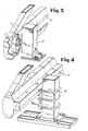
- Fig. 3 in wiederum größeren Maßstab eine Ansicht auf die offene Seite der Hohlprofilschiene und in
- Fig. 4 eine Ansicht auf eine abgeänderte Ausführungsform gemäß der Erfindung.
- In Fig. 1 ist mit 1 der Boden bezeichnet, auf dem ein ortsfester Träger 2 fest angeordnet ist. Der ortsfeste Träger 2 trägt in seinem unteren Bereich, beispielsweise über Schraubmittel 3 und 4 festgelegt, eine Laufachse 5, die ortsfest gelagert ist und vom ortsfesten Träger 2 aus gesehen zur Seite vorspringt. Die Laufachse 5 trägt unter Zwischenschaltung von Kugellagern 6 eine Laufrolle 7. Der untere Bereich des eigentlichen Schiebetores wird durch eine C-förmige hohlprofilförmige Führungsschiene 8 gebildet, die in ihrem Inneren die Laufrolle 7 aufnimmt, wobei die durch die beiden Endschenkel des C-profilförmigen Bauteiles gebildete Öffnung von der Laufachse 5 durchquert wird und - wie dies in der Zeichnung nicht dargestellt ist - dort durch eine elastische Dichtung, beispielsweise eine Gummilippendichtung, abgedichtet sein kann.
- Im unteren Teil des ortsfesten Trägers 2 ist die Laufachse 5 angeordnet, während im oberen Teil des ortsfesten Trägers 2 Führungsrollen 9 und 10 vorgesehen sind, die an einer am Schiebetor in dessen oberem Bereich vorgesehenen Führung 11 außen anliegen.
- In einem horizontalen Abstand vom ortsfesten Träger 2 ist ein weiterer ortsfester Träger 12 vorgesehen, der ebenfalls eine Laufrolle 7 aufnimmt, die in gleicher Weise, wie anhand von Fig. 1 erläutert, in die C-förmige, hohlprofilförmige Führungsschiene 8 eingreift.
- Das eigentliche Schiebetor 14 weist an seinem dem ortsfesten Träger 2 bzw. 12 zugewandten Ende eine Zug- und Druckstrebe 15 auf, die von der oberen Führung 11 zur Führungsschiene 8 führt und hier für die erforderliche Festigkeit sorgt.
- Es ist erkennbar, daß die Führungsrollen 7 sich innerhalb der Führungsschiene 8 geschützt führen und daß die Führungsschiene 8 aufgrund der ihr gegegebenen Formgebung die ausreichende Festigkeit aufweist, so daß das gesamte frei vorkragende Schiebetor 14 nur im Bereich der beiden ortsfesten Träger 12 und 2 getragen wird.
- Die Führungsschiene 8 wird dabei vorzugsweise aus einem einteiligen Materialstrang durch Kanten oder Walzen hergestellt und weist aufgrund der ihr eigenen Profilgebung die erforderliche Festigkeit auf. Natürlich ist es auch möglich, die Führungsschiene 8 auch aus zwei oder mehreren Teilen zusammenzusetzen.
- Die Laufrollen 7 können aus Kunststoff bestehen und damit korrosionsfest gestaltet sein.
- In Fig. 3 ist erkennbar, wie der Träger 12 zur Führungsschiene 8 angeordnet ist und daß die Laufachse 5 durch die Öffnung der Führungsschiene 8 greift. Im Inneren der Führungsschiene 8 ist teilweise die Laufrolle 7 erkennbar.
- Bei der in Fig. 4 dargestellten Ausführungsform ist erkennbar, daß die Halterung der Laufachse 5 über einfache Klemmbügel 16 erfolgen kann. Bei dem in Fig. 4 dargestellten Ausführungsbeispiel ist weiterhin oberhalb der Öffnung der Führungsschiene 8 eine Regenschutzschiene 17 angeordnet, die ein Eindringen von Wasser oder sonstigen Verunreinigungen in die Öffnung der Führungsschiene 8 verhindert. Bei dieser Ausführungsform kann dabei so vorgegangen werden, daß die Laufachse 5 für die Laufrolle 7 nach oben abgekröpft ist, so daß damit die Regenschutzschiene 17 die Öffnung in der Führungsschiene 8 voll abdeckt.
Claims (7)
Priority Applications (1)
| Application Number | Priority Date | Filing Date | Title |
|---|---|---|---|
| AT83104690T ATE33514T1 (de) | 1982-05-13 | 1983-05-12 | Schiebetor. |
Applications Claiming Priority (2)
| Application Number | Priority Date | Filing Date | Title |
|---|---|---|---|
| DE19828213933U DE8213933U1 (de) | 1982-05-13 | 1982-05-13 | Schiebetor |
| DE8213933U | 1982-05-13 |
Publications (3)
| Publication Number | Publication Date |
|---|---|
| EP0094628A2 EP0094628A2 (de) | 1983-11-23 |
| EP0094628A3 EP0094628A3 (en) | 1984-11-28 |
| EP0094628B1 true EP0094628B1 (de) | 1988-04-13 |
Family
ID=6740070
Family Applications (1)
| Application Number | Title | Priority Date | Filing Date |
|---|---|---|---|
| EP83104690A Expired EP0094628B1 (de) | 1982-05-13 | 1983-05-12 | Schiebetor |
Country Status (3)
| Country | Link |
|---|---|
| EP (1) | EP0094628B1 (de) |
| AT (1) | ATE33514T1 (de) |
| DE (2) | DE8213933U1 (de) |
Cited By (2)
| Publication number | Priority date | Publication date | Assignee | Title |
|---|---|---|---|---|
| DE9310090U1 (de) * | 1993-07-07 | 1995-02-16 | Adronit Verwaltungsgesellschaft mbH, 58300 Wetter | Freitragendes Schiebetor |
| US11649675B2 (en) | 2021-03-17 | 2023-05-16 | Troy Hinojosa | Gate opener assembly |
Families Citing this family (7)
| Publication number | Priority date | Publication date | Assignee | Title |
|---|---|---|---|---|
| DE3619516A1 (de) * | 1986-06-10 | 1987-12-17 | Zapf Juergen | Schiebetor |
| US4969300A (en) * | 1990-02-12 | 1990-11-13 | Pope Ralph E | Rotatable building |
| IL156245A0 (en) | 2000-12-22 | 2004-01-04 | Dca Design Int Ltd | Drive mechanism for an injection device |
| GB2434393A (en) * | 2006-01-18 | 2007-07-25 | Strongarm Ltd | Barrier system for restricting vehicular access to a roadway |
| US8931213B2 (en) * | 2006-07-14 | 2015-01-13 | Ceta Elektromechanik Gmbh | Apparatus for sliding gates or sliding doors |
| JP2010188896A (ja) * | 2009-02-19 | 2010-09-02 | Nabtesco Corp | ホームドア装置 |
| USD950773S1 (en) | 2020-07-30 | 2022-05-03 | Troy Hinojosa | Gate opener stand |
Family Cites Families (3)
| Publication number | Priority date | Publication date | Assignee | Title |
|---|---|---|---|---|
| DE1216514B (de) * | 1962-09-19 | 1966-05-12 | Gebhard Huegle | Schiebetoranlage |
| DE1559958B1 (de) * | 1965-12-21 | 1971-05-13 | Malkmus Doernemann Carola | Freitragendes Schiebetor |
| DE1683259C3 (de) * | 1966-12-07 | 1974-11-21 | Carola Dr. 3320 Salzgitter Malkmus-Doernemann Geb. Doernemann | Freitragendes Schiebetor |
-
1982
- 1982-05-13 DE DE19828213933U patent/DE8213933U1/de not_active Expired
-
1983
- 1983-05-12 EP EP83104690A patent/EP0094628B1/de not_active Expired
- 1983-05-12 DE DE8383104690T patent/DE3376274D1/de not_active Expired
- 1983-05-12 AT AT83104690T patent/ATE33514T1/de not_active IP Right Cessation
Cited By (2)
| Publication number | Priority date | Publication date | Assignee | Title |
|---|---|---|---|---|
| DE9310090U1 (de) * | 1993-07-07 | 1995-02-16 | Adronit Verwaltungsgesellschaft mbH, 58300 Wetter | Freitragendes Schiebetor |
| US11649675B2 (en) | 2021-03-17 | 2023-05-16 | Troy Hinojosa | Gate opener assembly |
Also Published As
| Publication number | Publication date |
|---|---|
| EP0094628A3 (en) | 1984-11-28 |
| DE8213933U1 (de) | 1982-10-14 |
| EP0094628A2 (de) | 1983-11-23 |
| DE3376274D1 (en) | 1988-05-19 |
| ATE33514T1 (de) | 1988-04-15 |
Similar Documents
| Publication | Publication Date | Title |
|---|---|---|
| DE19638156B4 (de) | Aufbau für oberen Karosserieabschnitt einer Fahrzeugkarosserie | |
| EP0327727B1 (de) | Führungseinrichtung für eine in der Höhe verstellbare Fensterscheibe | |
| DE4224866A1 (de) | Vorrichtung zum Wischen von Scheiben von Kraftfahrzeugen | |
| EP0094628A2 (de) | Schiebetor | |
| DE3906682A1 (de) | Seil-umlenkvorrichtung | |
| DE102014119145A1 (de) | Schiebetor und Baukastensystem für ein Schiebetor | |
| WO2007059882A1 (de) | Wand- oder türelement | |
| EP0016958A1 (de) | Rahmenprofil für ein Fenster, eine Tür od. dgl. | |
| DE3448196C2 (en) | Adjustable rail for a sliding door, especially fire door | |
| EP0384215B1 (de) | Duschkabinen-Schiebetür IV | |
| EP1160111A2 (de) | Kraftfahrzeugtür mit Fensterschachtverstärkung | |
| EP1165922A1 (de) | Antriebseinrichtung für einen schiebeflügel | |
| DE3526288C2 (de) | ||
| DE3411544C2 (de) | Sektionaltor | |
| DE8226126U1 (de) | Aussenlaufende doppelschiebetuer fuer fahrzeuge | |
| DE3809846A1 (de) | Fahrzeugtuer mit tuerrahmen und scheibenfuehrungsrahmen sowie verfahren zum montieren eines scheibenfuehrungsrahmens | |
| EP1281655B1 (de) | Fahrschachttür | |
| DE1509219C3 (de) | ||
| DE3525295C2 (de) | Sektionaltor | |
| DE2013319B2 (de) | Abdichtvorrichtung für Schwing- oder Wendeflügel von Fenstern, Türen od.dgl | |
| DE19501045C2 (de) | Führungsrolle zur Befestigung am unteren Rand eines Schiebetores oder dergl., insbesondere für eine Garage | |
| DE10318251B4 (de) | Torantrieb, insbesondere für Schwing- oder Sektionaltore | |
| DE3447402A1 (de) | Garagentor, zaun oder dergleichen | |
| DE2547616B2 (de) | Feststehender Metallrahmen für horizontal bewegbare Schiebefenster oder Schiebetüren | |
| EP0807742A2 (de) | Kunststoffprofilschiene für einen Garagentorantrieb |
Legal Events
| Date | Code | Title | Description |
|---|---|---|---|
| PUAI | Public reference made under article 153(3) epc to a published international application that has entered the european phase |
Free format text: ORIGINAL CODE: 0009012 |
|
| AK | Designated contracting states |
Designated state(s): AT BE DE FR GB NL |
|
| PUAL | Search report despatched |
Free format text: ORIGINAL CODE: 0009013 |
|
| AK | Designated contracting states |
Designated state(s): AT BE DE FR GB NL |
|
| 17P | Request for examination filed |
Effective date: 19850325 |
|
| 17Q | First examination report despatched |
Effective date: 19860507 |
|
| GRAA | (expected) grant |
Free format text: ORIGINAL CODE: 0009210 |
|
| AK | Designated contracting states |
Kind code of ref document: B1 Designated state(s): AT BE DE FR GB NL |
|
| REF | Corresponds to: |
Ref document number: 33514 Country of ref document: AT Date of ref document: 19880415 Kind code of ref document: T |
|
| REF | Corresponds to: |
Ref document number: 3376274 Country of ref document: DE Date of ref document: 19880519 |
|
| ET | Fr: translation filed | ||
| GBV | Gb: ep patent (uk) treated as always having been void in accordance with gb section 77(7)/1977 [no translation filed] | ||
| PG25 | Lapsed in a contracting state [announced via postgrant information from national office to epo] |
Ref country code: GB Free format text: LAPSE BECAUSE OF NON-PAYMENT OF DUE FEES Effective date: 19881122 |
|
| PLBE | No opposition filed within time limit |
Free format text: ORIGINAL CODE: 0009261 |
|
| STAA | Information on the status of an ep patent application or granted ep patent |
Free format text: STATUS: NO OPPOSITION FILED WITHIN TIME LIMIT |
|
| 26N | No opposition filed | ||
| PGFP | Annual fee paid to national office [announced via postgrant information from national office to epo] |
Ref country code: AT Payment date: 19890512 Year of fee payment: 7 |
|
| PG25 | Lapsed in a contracting state [announced via postgrant information from national office to epo] |
Ref country code: AT Effective date: 19900512 |
|
| PGFP | Annual fee paid to national office [announced via postgrant information from national office to epo] |
Ref country code: BE Payment date: 19930330 Year of fee payment: 11 |
|
| PGFP | Annual fee paid to national office [announced via postgrant information from national office to epo] |
Ref country code: FR Payment date: 19930528 Year of fee payment: 11 |
|
| PGFP | Annual fee paid to national office [announced via postgrant information from national office to epo] |
Ref country code: NL Payment date: 19930531 Year of fee payment: 11 |
|
| PG25 | Lapsed in a contracting state [announced via postgrant information from national office to epo] |
Ref country code: BE Effective date: 19940531 |
|
| BERE | Be: lapsed |
Owner name: BERLEMANN KLAUS Effective date: 19940531 |
|
| PG25 | Lapsed in a contracting state [announced via postgrant information from national office to epo] |
Ref country code: NL Effective date: 19941201 |
|
| NLV4 | Nl: lapsed or anulled due to non-payment of the annual fee | ||
| PG25 | Lapsed in a contracting state [announced via postgrant information from national office to epo] |
Ref country code: FR Effective date: 19950131 |
|
| REG | Reference to a national code |
Ref country code: FR Ref legal event code: ST |
|
| PGFP | Annual fee paid to national office [announced via postgrant information from national office to epo] |
Ref country code: DE Payment date: 19950712 Year of fee payment: 13 |
|
| PG25 | Lapsed in a contracting state [announced via postgrant information from national office to epo] |
Ref country code: DE Effective date: 19970201 |