EP0094698A1 - Rohr-Verlegegelenkrampe und Verfahren zum Verlegen einer Pipeline - Google Patents
Rohr-Verlegegelenkrampe und Verfahren zum Verlegen einer Pipeline Download PDFInfo
- Publication number
- EP0094698A1 EP0094698A1 EP83200499A EP83200499A EP0094698A1 EP 0094698 A1 EP0094698 A1 EP 0094698A1 EP 83200499 A EP83200499 A EP 83200499A EP 83200499 A EP83200499 A EP 83200499A EP 0094698 A1 EP0094698 A1 EP 0094698A1
- Authority
- EP
- European Patent Office
- Prior art keywords
- pipe discharge
- discharge ramp
- articulated pipe
- vessel
- pipeline
- Prior art date
- Legal status (The legal status is an assumption and is not a legal conclusion. Google has not performed a legal analysis and makes no representation as to the accuracy of the status listed.)
- Granted
Links
- 238000000034 method Methods 0.000 title claims description 17
- 238000005553 drilling Methods 0.000 claims description 12
- 238000003032 molecular docking Methods 0.000 claims description 8
- PEDCQBHIVMGVHV-UHFFFAOYSA-N Glycerine Chemical compound OCC(O)CO PEDCQBHIVMGVHV-UHFFFAOYSA-N 0.000 claims description 7
- 238000007373 indentation Methods 0.000 claims description 4
- QGFSVPWZEPKNDV-BRTFOEFASA-N ranp Chemical compound C([C@H]1C(=O)NCC(=O)NCC(=O)N[C@@H](CCCNC(N)=N)C(=O)N[C@H](C(=O)N[C@@H](CC(O)=O)C(=O)N[C@@H](CCCNC(N)=N)C(=O)N[C@H](C(NCC(=O)N[C@@H](C)C(=O)N[C@@H](CCC(N)=O)C(=O)N[C@@H](CO)C(=O)NCC(=O)N[C@@H](CC(C)C)C(=O)NCC(=O)N[C@@H](CSSC[C@@H](C(=O)N1)NC(=O)[C@H](CO)NC(=O)[C@H](CO)NC(=O)[C@H](CCCNC(N)=N)NC(=O)[C@H](CCCNC(N)=N)NC(=O)[C@H](CC(C)C)NC(=O)[C@@H](N)CO)C(=O)N[C@@H](CC(N)=O)C(=O)N[C@@H](CO)C(=O)N[C@@H](CC=1C=CC=CC=1)C(=O)N[C@@H](CCCNC(N)=N)C(=O)N[C@@H](CC=1C=CC(O)=CC=1)C(O)=O)=O)[C@@H](C)CC)[C@@H](C)CC)C1=CC=CC=C1 QGFSVPWZEPKNDV-BRTFOEFASA-N 0.000 claims description 3
- 230000013011 mating Effects 0.000 claims 1
- 238000005452 bending Methods 0.000 description 13
- 230000033001 locomotion Effects 0.000 description 5
- 239000003643 water by type Substances 0.000 description 4
- 230000009286 beneficial effect Effects 0.000 description 2
- 125000004122 cyclic group Chemical group 0.000 description 2
- 239000002184 metal Substances 0.000 description 2
- XLYOFNOQVPJJNP-UHFFFAOYSA-N water Substances O XLYOFNOQVPJJNP-UHFFFAOYSA-N 0.000 description 2
- 230000002411 adverse Effects 0.000 description 1
- 238000006243 chemical reaction Methods 0.000 description 1
- 238000005188 flotation Methods 0.000 description 1
- 238000005096 rolling process Methods 0.000 description 1
Images


Classifications
-
- F—MECHANICAL ENGINEERING; LIGHTING; HEATING; WEAPONS; BLASTING
- F16—ENGINEERING ELEMENTS AND UNITS; GENERAL MEASURES FOR PRODUCING AND MAINTAINING EFFECTIVE FUNCTIONING OF MACHINES OR INSTALLATIONS; THERMAL INSULATION IN GENERAL
- F16L—PIPES; JOINTS OR FITTINGS FOR PIPES; SUPPORTS FOR PIPES, CABLES OR PROTECTIVE TUBING; MEANS FOR THERMAL INSULATION IN GENERAL
- F16L1/00—Laying or reclaiming pipes; Repairing or joining pipes on or under water
- F16L1/12—Laying or reclaiming pipes on or under water
- F16L1/20—Accessories therefor, e.g. floats or weights
- F16L1/225—Stingers
-
- F—MECHANICAL ENGINEERING; LIGHTING; HEATING; WEAPONS; BLASTING
- F16—ENGINEERING ELEMENTS AND UNITS; GENERAL MEASURES FOR PRODUCING AND MAINTAINING EFFECTIVE FUNCTIONING OF MACHINES OR INSTALLATIONS; THERMAL INSULATION IN GENERAL
- F16L—PIPES; JOINTS OR FITTINGS FOR PIPES; SUPPORTS FOR PIPES, CABLES OR PROTECTIVE TUBING; MEANS FOR THERMAL INSULATION IN GENERAL
- F16L1/00—Laying or reclaiming pipes; Repairing or joining pipes on or under water
- F16L1/12—Laying or reclaiming pipes on or under water
- F16L1/16—Laying or reclaiming pipes on or under water on the bottom
- F16L1/18—Laying or reclaiming pipes on or under water on the bottom the pipes being S- or J-shaped and under tension during laying
- F16L1/19—Laying or reclaiming pipes on or under water on the bottom the pipes being S- or J-shaped and under tension during laying the pipes being J-shaped
-
- Y—GENERAL TAGGING OF NEW TECHNOLOGICAL DEVELOPMENTS; GENERAL TAGGING OF CROSS-SECTIONAL TECHNOLOGIES SPANNING OVER SEVERAL SECTIONS OF THE IPC; TECHNICAL SUBJECTS COVERED BY FORMER USPC CROSS-REFERENCE ART COLLECTIONS [XRACs] AND DIGESTS
- Y10—TECHNICAL SUBJECTS COVERED BY FORMER USPC
- Y10T—TECHNICAL SUBJECTS COVERED BY FORMER US CLASSIFICATION
- Y10T403/00—Joints and connections
- Y10T403/32—Articulated members
- Y10T403/32008—Plural distinct articulation axes
- Y10T403/32032—Plural ball and socket
-
- Y—GENERAL TAGGING OF NEW TECHNOLOGICAL DEVELOPMENTS; GENERAL TAGGING OF CROSS-SECTIONAL TECHNOLOGIES SPANNING OVER SEVERAL SECTIONS OF THE IPC; TECHNICAL SUBJECTS COVERED BY FORMER USPC CROSS-REFERENCE ART COLLECTIONS [XRACs] AND DIGESTS
- Y10—TECHNICAL SUBJECTS COVERED BY FORMER USPC
- Y10T—TECHNICAL SUBJECTS COVERED BY FORMER US CLASSIFICATION
- Y10T403/00—Joints and connections
- Y10T403/32—Articulated members
- Y10T403/32008—Plural distinct articulation axes
- Y10T403/32057—Angular and linear
Definitions
- the present invention relates to an articulated pipe discharge ramp attachable to a pipelaying vessel for guiding a pipeline being laid from said vessel, and to a method for laying a pipeline from a pipelaying vessel.
- a typical pipelaying operation involves assembling the pipeline by adding one section of pipe at a time on the pipelaying vessel and then moving the vessel ahead as the assembled pipeline is paid out and laid onto the ocean floor.
- the pipeline may be preassembled and wound onto a rotatable reel which has been mounted on the vessel. The pipeline then is spooled off the reel and laid onto the sea floor after the vessel arrives at the proper field location.
- any pipeline is capable of withstanding some bending but such bending must stay within predetermined limits to avoid buckling due to excessive bending or metal fatiguing due to cyclic bending.
- the pipeline exits the vessel and follows a more or less "S" shaped configuration from the vessel deck to the ocean floor.
- the small vertical descent of the unsupported pipeline results in a large radius of curvature of the pipeline as it cams off the vessel, and the pipeline remains safe from bending damage.
- the length of unsupported pipeline increases, causing the pipeline to sag under its own weight.
- the radius of curvature of the pipeline as it leaves the vessel becomes smaller and the bending moments imposed on the pipeline may well exceed the allowable limits and result in permanent deformation of the pipeline.
- an articulated pipe discharge ramp is used to control the bending of the pipe in the overbend portion of the suspended pipeline span.
- This pipe discharge ramp generally is a long, slender, rigid structure which extends outward and curves downward from the stern end of the pipelaying vessel, and contains rollers for supporting and paying out the pipeline as the pipelaying vessel moves forward.
- the pipe discharge ramp often is used in conjunction with flotation means to force the pipeline to assume a curvature whose minimum radius is large enough to avoid undue bending.
- the articulated pipe discharge ramp attachable to a pipelaying vessel for guiding a pipeline being laid from said vessel comprises according to the invention a plurality of elongated interconnected multi-leg segments arranged in end-to-end relationship and joint means interconnecting at least a pair of said segments to allow said segments to flex in any direction within a preselected angle.
- the invention relates moreover to a method for laying a pipeline from a pipelaying vessel, which method comprises according to the invention attaching an articulated pipe discharge ramp in a vertically hanging position to the pipelaying vessel, deploying pipeline through the articulated pipe discharge ramp, and allowing the pipe discharge ramp to flex in any direction within a preselected angle responsive to forces exerted on the deployed pipeline.
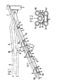
- Figure 1 shows a vertical cross-section of an articulated pipe discharge ramp 1 according to the invention connected to the rear end of a pipelaying vessel 2, wherein the articulated pipe discharge ramp 1 comprises a first segment 3 and a second segment 4.
- the first segment 3 comprises four legs in the form of tubular sections of which only the tubular sections 3a and 3b are shown in Figure 1
- the second segment 4 comprises four legs as well.
- the latter legs, in the form of tubular sections 4a, 4b, 4c and 4d are shown in Figure 2.
- the legs are interconnected by horizontal connecting members 5 and vertical connecting members 6.
- a pipeline 7 passes out of the rear of the pipelaying vessel 2 and is cradled by a plurality of rollers 8 arranged along the pipe discharge ranp 1.
- the pipe discharge ramp 1 is able to substantially flex as shown particularly at joint 9 which is closed and joint 10 which is open. When the pipe discharge ramp 1 is in a raised mode as shown in phantom, joint 9 is open and joint 10 is closed. Such flexibility improves the lifetime of the pipe discharge ramp 1 and reduces the contact loads applied to the pipeline 7 while laying a pipeline in rough seas.
- the advantage of the articulated pipe discharge ramp according to the invention is that the joints allow the segments to flex in any direction within a preselected angle.
- the joints allow more control of the vertical and lateral motions of the pipe discharge ramp than the joints of existing pipe discharge ramps, as the existing pipe discharge ramps were only provided with bumper stops to control the downward curvature of the pipe discharge ramp.
- the additional control of the motions of the articulated pipe discharge ramp according to the invention is beneficial to the lifetime of the pipe discharge ramp.
- a necessary part of the conversion of an existing drilling vessel, semisubmersible drilling rig, or other vessel to pipelaying is the use of a vertical articulated pipe discharge ramp, which is attached to the bottom hull of the drilling ship or other vessel, or beneath or off the side of the semisubmersible rig for the purpose of guiding and protecting the pipeline being deployed to the ocean floor.
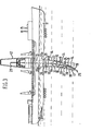
- FIG 3 shows a pipelaying vessel in the form of a deepwater drilling ship 11, for carrying out the J-method of pipelaying.
- the drilling ship 11 is provided with a derrick 12, a moon pool 13 and a vertical articulated pipe discharge ramp 14, comprising three segments 15, 16 and 17.
- the segments are similar to the second segment as described with reference to Figure 1 and comprise four legs in the form of tubular sections 18.
- the tubular sections 18 are connected to each other by first connecting members 19 and second connecting members (not shown) which are perpendicular to the plane of drawing of Figure 3.
- the articulated pipe discharge ramp 14 is able to substantially flex as shewn particularly at joints 21 and 22 which are closed and joints 23 and 24 which are open in the position as shown in Figure 3. When the pipe discharge ramp 14 is in a vertical position, as shown in phantom, all joints are open.
- Pipeline 25 is put together into a pipeline in the derrick 12 and is then passed through the moon pool 13 and the pipe discharge ramp 14.
- the articulated pipe discharge ramp 14 is attached to the drilling ship 11 by docking cones 26 which mate with corresponding indentations 26a in the hull of the drilling ship 11. Connection and release of the pipe discharge ramp 14 is carried out with the use of lugs or cams (not shown) at each docking cone 26.
- the lugs or cams are actuated hydraulically or by wirelines, to secure the pipe discharge ramp 14 at the docking cones 26.
- a significant feature of the articulated pipe discharge ramp according to the invention is that joints interconnecting a pair of segments arranged in end-to-end relationship allow these segments to flex in any direction within a preselected angle.
- the angles within which the segments 16 and 17 can flex are selected in such a manner that the lower segment 17 is allowed to rotate up to 20 degrees from the vertical in order to accommodate pipeline deflections up to 20 degrees from the vertical.
- the pipeline may be deflected from the vertical axis by horizontal forces applied to the pipeline to control sag bend strains, ocean currents, or pitch and roll motions of the pipelaying vessel.
- Both the horizontal forces and the resultant current drag forces may act in directions skew to the vessel heading, so that the pipeline in general will approach the vessel obliquely to the vessel axis.
- the main function of the articulated pipe discharge ramp is to control the curvatures of the upper end of the pipeline span under such adverse conditions. Without an articulated pipe discharge ramp, the pipeline could fail by buckling due to excessive bending in one direction or by metal fatigue due to cyclic bending.
- Figures 4A and 4B show a joint employing a dumb-bell.
- the connected socket-filling members in the form of a dumb-bell, connecting leg 28 of a first segment to leg 29 of. a second segment comprises a shaft 30 and two spheres 31 and 32 at either end thereof.
- the spheres 31 and 32 may be attached to the shaft 30 by threads 33 or in any other manner known to the art.
- the spheres 31 and 32 have flattened ends 34 which allows them to abut within the outer case 35 attached to the end portion of leg 28 and the outer case 36 attached to the end portion of leg 29 without doing damage thereto.
- Figure 4A shows the joint in a closed position with the outer case 35 of one side abutting the outer case 36 of the other side.
- Figure 4B shows the joint in an opened position with the spheres 31 and 32 abutting the ends of the outer cases 35 and 36.
- the outer cases 35 and 36 may be manufactured in one piece, as shown in Figure 4A, or in two pieces by attaching end closures 37 and 38 to the sockets 35a and 36a of the outer cases 35 and 36, thereby enclosing the spheres 31 and 32.
- FIGS 5A and 5B Another type of the joint is shown in Figures 5A and 5B wherein a doubleheaded bolt with rubber dampers is employed.
- the doubleheaded bolt, connecting leg 40 of a first segment to leg 41 of a second segment includes a shaft 42 and heads in the form of nuts 43 and 44 attached at either end thereof by threads 45.
- Cushioning means in the form of rubber dampers 47 and 48 within outer cases 49 and 50 provide resilient seating for the nuts 43 and 44 within the . outer cases 49 and 50.
- Figure 5A shows the joint in a closed position
- Figure 5B shows the joint in an open position.
- the rubber dampers 47 and 48 are enclosed within the outer cases 49 and 50 by attaching end closures 51 and 52 to the sockets 49a and 50a.
- segments of the articulated pipe discharge ramp have more than two longitudinal legs, for example three or four, there will be three or four joints used between each pair of segments.
Landscapes
- Engineering & Computer Science (AREA)
- General Engineering & Computer Science (AREA)
- Mechanical Engineering (AREA)
- Earth Drilling (AREA)
- Joints Allowing Movement (AREA)
- Supports For Pipes And Cables (AREA)
- Credit Cards Or The Like (AREA)
- Luminescent Compositions (AREA)
- Valve Device For Special Equipments (AREA)
- Sewage (AREA)
- Non-Disconnectible Joints And Screw-Threaded Joints (AREA)
Applications Claiming Priority (2)
| Application Number | Priority Date | Filing Date | Title |
|---|---|---|---|
| US06/379,594 US4472079A (en) | 1982-05-19 | 1982-05-19 | Articulated pipe discharge ramp |
| US379594 | 1982-05-19 |
Publications (2)
| Publication Number | Publication Date |
|---|---|
| EP0094698A1 true EP0094698A1 (de) | 1983-11-23 |
| EP0094698B1 EP0094698B1 (de) | 1985-10-16 |
Family
ID=23497875
Family Applications (1)
| Application Number | Title | Priority Date | Filing Date |
|---|---|---|---|
| EP83200499A Expired EP0094698B1 (de) | 1982-05-19 | 1983-04-08 | Rohr-Verlegegelenkrampe und Verfahren zum Verlegen einer Pipeline |
Country Status (9)
| Country | Link |
|---|---|
| US (1) | US4472079A (de) |
| EP (1) | EP0094698B1 (de) |
| JP (1) | JPS58217882A (de) |
| AU (1) | AU553986B2 (de) |
| CA (1) | CA1202791A (de) |
| DZ (1) | DZ542A1 (de) |
| ES (1) | ES522475A0 (de) |
| IE (1) | IE54320B1 (de) |
| NO (1) | NO158592C (de) |
Cited By (4)
| Publication number | Priority date | Publication date | Assignee | Title |
|---|---|---|---|---|
| GB2321290A (en) * | 1997-01-17 | 1998-07-22 | Mcdermott Sa J Ray | Laying of underwater pipeline from a vessel-mounted drum |
| RU2131550C1 (ru) * | 1993-11-18 | 1999-06-10 | Макдермотт Интернешнл, Инк. | Установка для почти вертикальной прокладки трубопровода |
| RU2140595C1 (ru) * | 1993-12-29 | 1999-10-27 | Макдермотт Интернешнл, Инк. | Установка для вертикальной прокладки трубопровода на акватории (варианты) |
| EP2583890A1 (de) | 2008-04-29 | 2013-04-24 | Itrec B.V. | System und Verfahren zur Verlegung von Hochseerohrleitungen |
Families Citing this family (17)
| Publication number | Priority date | Publication date | Assignee | Title |
|---|---|---|---|---|
| JPH0542158Y2 (de) * | 1987-05-07 | 1993-10-25 | ||
| US5642956A (en) * | 1996-01-25 | 1997-07-01 | Regents Of The University Of California | Adjustable link for kinematic mounting systems |
| US5983822A (en) * | 1998-09-03 | 1999-11-16 | Texaco Inc. | Polygon floating offshore structure |
| US6230645B1 (en) | 1998-09-03 | 2001-05-15 | Texaco Inc. | Floating offshore structure containing apertures |
| US6409695B1 (en) * | 1999-07-27 | 2002-06-25 | John D. Connelly | Ankle-foot orthotic |
| GB2379259B (en) * | 2001-08-22 | 2004-10-27 | Rockwater Ltd | Apparatus and method for laying a conduit on the seabed from a floating vessel |
| GB0124853D0 (en) * | 2001-10-16 | 2001-12-05 | Rockwater Ltd | Apparatus and method for use in laying or recovering offshore pipelines or cables |
| US6776560B2 (en) * | 2002-06-13 | 2004-08-17 | Mark Moszkowski | Flex J-Lay tower |
| US7255515B2 (en) * | 2004-03-22 | 2007-08-14 | Itrec B.V. | Marine pipelay system and method |
| FR2881171B1 (fr) * | 2005-01-21 | 2008-07-18 | D2M Consultants S A Sa | Structure de guidage de canalisations reliant le fond marin a un support flottant |
| BRPI0520784A2 (pt) * | 2005-12-21 | 2009-10-06 | Itrec Bv | sistema fora da costa, métodos para depositar uma tubulação, e para montar uma torre de deposição em j |
| MX2010005555A (es) * | 2007-11-20 | 2010-11-12 | Keith K Millheim | Embarcacion de despliegue de tuberia continua en altamar. |
| ITMI20080205A1 (it) * | 2008-02-08 | 2009-08-09 | Saipem Spa | Dispositivo di guida per supportare una tubazione subacquea, rampa di varo comprendente tale dispositivo di guida, natante di posa provvisto di tale rampa di varo e metodo di controllo della rampa di varo di una tubazione subacquea |
| BRPI0822751A2 (pt) * | 2008-06-03 | 2015-06-23 | Heerema Marine Contractors Nl | Conjunto-guia de tubulação, embarcação para assentamento de tubulações, e, método de assentamento de uma tubulação. |
| GB201101579D0 (en) | 2011-01-28 | 2011-03-16 | Saipem Spa | Pipe-laying vessel and method of laying a pipeline |
| GB201101577D0 (en) | 2011-01-28 | 2011-03-16 | Saipem Spa | Clamp assembly for pipe-laying vessel and method of laying a pipeline |
| GB201121118D0 (en) | 2011-12-08 | 2012-01-18 | Saipem Spa | Method and vessel for laying a pipeline |
Citations (6)
| Publication number | Priority date | Publication date | Assignee | Title |
|---|---|---|---|---|
| DE736447C (de) * | 1940-08-09 | 1943-06-17 | Franz Von Hennet | Gelenkkette aus raumbeweglich miteinander verbundenen Kettengliedern |
| GB1479905A (en) * | 1973-10-31 | 1977-07-13 | Saipem Spa | Structure for use in an articulated ramp an articulated ramp and its use |
| DE2831732A1 (de) * | 1977-12-27 | 1979-06-28 | Saipem Spa | Rohrleger und verfahren zum verlegen von rohren auf dem meeresboden |
| GB2019976A (en) * | 1978-04-28 | 1979-11-07 | Petroles Cie Francaise | Suspension of an immersed elongate product |
| US4236738A (en) * | 1977-04-15 | 1980-12-02 | Machinefabriek Kreber B.V. | Ball joint for two pipe ends |
| GB1582116A (en) * | 1977-05-20 | 1980-12-31 | Brown & Root | Articulated stinger apparatus |
Family Cites Families (25)
| Publication number | Priority date | Publication date | Assignee | Title |
|---|---|---|---|---|
| US443769A (en) * | 1890-12-30 | Drive-chain | ||
| US28922A (en) * | 1860-06-26 | Window-curtain slide | ||
| US29591A (en) * | 1860-08-14 | Improvement in plows | ||
| US684264A (en) * | 1901-01-12 | 1901-10-08 | Charles D Kemmerer | Lamp-hanger. |
| US3331212A (en) * | 1964-03-23 | 1967-07-18 | Shell Oil Co | Tension pipe laying method |
| US3280571A (en) * | 1965-04-30 | 1966-10-25 | Brown & Root | Methods and apparatus for laying elongate flexible means on a submerged surface |
| US3559413A (en) * | 1968-02-07 | 1971-02-02 | Pan American Petroleum Corp | Adjustable stinger for use in laying pipeline in water covered areas |
| US3555835A (en) * | 1968-08-16 | 1971-01-19 | Healy Tibbitts Construction Co | Suspended pipe laying stringer for laying pipelines in unlimited depths of water |
| US3538712A (en) * | 1968-11-08 | 1970-11-10 | Brown & Root | Method and apparatus for connecting a rigid ramp used for pipelaying operations to a marine vessel |
| US3517519A (en) * | 1969-02-10 | 1970-06-30 | Shell Oil Co | Adjustable vessel pipe ramp with elastically flexible hinge joints |
| US3641779A (en) * | 1970-03-24 | 1972-02-15 | Fluor Corp | Stinger system for guiding a pipeline from or on a moving vessel |
| US3704596A (en) | 1970-03-25 | 1972-12-05 | Santa Fe Int Corp | Column stabilized stinger transition segment and pipeline supporting apparatus |
| US3670511A (en) * | 1970-04-01 | 1972-06-20 | Fluor Corp | Rigid stinger with adjustable pipeline curvature means |
| US3685305A (en) * | 1970-08-17 | 1972-08-22 | Santa Fe Int Corp | Column stabilized stinger |
| USRE28922E (en) | 1970-08-17 | 1976-08-03 | Santa Fe International Corporation | Column stabilized stinger |
| US3739590A (en) * | 1971-09-07 | 1973-06-19 | Exxon Production Research Co | Stinger connection |
| GB1404775A (en) * | 1971-10-06 | 1975-09-03 | Exxon Production Research Co | Articulated riser |
| US3736760A (en) * | 1971-10-07 | 1973-06-05 | Fluor Corp | Laterally-stabilized stinger suspension system |
| IT971058B (it) * | 1972-11-21 | 1974-04-30 | Saipem Spa | Metodo ed apparato perfezionati per la posa di tubazioni sul fon do marino da un pontone adatti per la posa in alti fondali di tubazio ni notevoli dimensioni |
| US3822559A (en) * | 1973-01-29 | 1974-07-09 | Exxon Production Research Co | Controlled yield stinger |
| JPS5420647B2 (de) * | 1973-05-21 | 1979-07-24 | ||
| US3911689A (en) * | 1973-09-19 | 1975-10-14 | Texaco Inc | Pipe laying vessel with stinger and method |
| US3922870A (en) * | 1974-10-24 | 1975-12-02 | Santa Fe Int Corp | Stinger latching apparatus |
| US3990259A (en) * | 1975-01-24 | 1976-11-09 | Exxon Production Research Company | Pipe support for floating pipelaying vessel and method of operating same |
| US3994140A (en) * | 1975-04-14 | 1976-11-30 | Exxon Production Research Company | Stinger coupling |
-
1982
- 1982-05-19 US US06/379,594 patent/US4472079A/en not_active Expired - Lifetime
-
1983
- 1983-04-08 EP EP83200499A patent/EP0094698B1/de not_active Expired
- 1983-04-12 CA CA000425673A patent/CA1202791A/en not_active Expired
- 1983-05-16 NO NO831742A patent/NO158592C/no not_active IP Right Cessation
- 1983-05-17 IE IE1150/83A patent/IE54320B1/en not_active IP Right Cessation
- 1983-05-17 DZ DZ836852A patent/DZ542A1/fr active
- 1983-05-17 JP JP58086515A patent/JPS58217882A/ja active Granted
- 1983-05-17 AU AU14604/83A patent/AU553986B2/en not_active Ceased
- 1983-05-17 ES ES522475A patent/ES522475A0/es active Granted
Patent Citations (6)
| Publication number | Priority date | Publication date | Assignee | Title |
|---|---|---|---|---|
| DE736447C (de) * | 1940-08-09 | 1943-06-17 | Franz Von Hennet | Gelenkkette aus raumbeweglich miteinander verbundenen Kettengliedern |
| GB1479905A (en) * | 1973-10-31 | 1977-07-13 | Saipem Spa | Structure for use in an articulated ramp an articulated ramp and its use |
| US4236738A (en) * | 1977-04-15 | 1980-12-02 | Machinefabriek Kreber B.V. | Ball joint for two pipe ends |
| GB1582116A (en) * | 1977-05-20 | 1980-12-31 | Brown & Root | Articulated stinger apparatus |
| DE2831732A1 (de) * | 1977-12-27 | 1979-06-28 | Saipem Spa | Rohrleger und verfahren zum verlegen von rohren auf dem meeresboden |
| GB2019976A (en) * | 1978-04-28 | 1979-11-07 | Petroles Cie Francaise | Suspension of an immersed elongate product |
Cited By (6)
| Publication number | Priority date | Publication date | Assignee | Title |
|---|---|---|---|---|
| RU2131550C1 (ru) * | 1993-11-18 | 1999-06-10 | Макдермотт Интернешнл, Инк. | Установка для почти вертикальной прокладки трубопровода |
| RU2140595C1 (ru) * | 1993-12-29 | 1999-10-27 | Макдермотт Интернешнл, Инк. | Установка для вертикальной прокладки трубопровода на акватории (варианты) |
| GB2321290A (en) * | 1997-01-17 | 1998-07-22 | Mcdermott Sa J Ray | Laying of underwater pipeline from a vessel-mounted drum |
| GB2321290B (en) * | 1997-01-17 | 2001-05-30 | Mcdermott Sa J Ray | Improvements relating to the laying of underwater pipeline |
| EP2583890A1 (de) | 2008-04-29 | 2013-04-24 | Itrec B.V. | System und Verfahren zur Verlegung von Hochseerohrleitungen |
| US8992124B2 (en) | 2008-04-29 | 2015-03-31 | Itrec B.V. | Marine pipelaying system and method |
Also Published As
| Publication number | Publication date |
|---|---|
| ES8501324A1 (es) | 1984-11-16 |
| IE54320B1 (en) | 1989-08-16 |
| ES522475A0 (es) | 1984-11-16 |
| NO831742L (no) | 1983-11-21 |
| CA1202791A (en) | 1986-04-08 |
| US4472079A (en) | 1984-09-18 |
| AU553986B2 (en) | 1986-07-31 |
| NO158592C (no) | 1988-10-05 |
| IE831150L (en) | 1983-11-19 |
| EP0094698B1 (de) | 1985-10-16 |
| NO158592B (no) | 1988-06-27 |
| DZ542A1 (fr) | 2004-09-13 |
| JPH0340271B2 (de) | 1991-06-18 |
| JPS58217882A (ja) | 1983-12-17 |
| AU1460483A (en) | 1983-11-24 |
Similar Documents
| Publication | Publication Date | Title |
|---|---|---|
| EP0094698B1 (de) | Rohr-Verlegegelenkrampe und Verfahren zum Verlegen einer Pipeline | |
| US5269629A (en) | Elastomeric swivel support assembly for catenary riser | |
| US4556340A (en) | Method and apparatus for production of subsea hydrocarbons using a floating vessel | |
| US8083439B2 (en) | Riser support system for use with an offshore platform | |
| US6062769A (en) | Enhanced steel catenary riser system | |
| US8562256B2 (en) | Floating system connected to an underwater line structure and methods of use | |
| US4185694A (en) | Marine riser system | |
| US20050158126A1 (en) | Flexible riser system | |
| WO2000031372A1 (en) | Tethered buoyant support for risers to a floating production vessel | |
| US20060056918A1 (en) | Riser system connecting two fixed underwater installations to a floating surface unit | |
| US5873395A (en) | Method for mooring floating storage vessels | |
| EP1080007B1 (de) | Umschlagrohrsystem | |
| WO2014032106A1 (en) | Buoy | |
| EP0907002B1 (de) | Stützsystem für Steigrohrleitung | |
| EP0079404B1 (de) | Einpunkt-Verankerungsboje mit starrem Arm | |
| US8690483B2 (en) | Method for assembling tendons | |
| US20070119359A1 (en) | Lashing of tender assist drilling unit to a floating production facility | |
| Langner | The articulated stinger: A new tool for laying offshore pipelines | |
| EP0960810A1 (de) | Umschlagrohrsystem | |
| GB2459739A (en) | A counterbalanced cantilever connector assembly for a vessel | |
| GB2210334A (en) | Floating production system and vessel for undersea oil well | |
| RU2773250C2 (ru) | Плавучая система и способ с плавучей надставкой и направляющей трубой | |
| JPS61155506A (ja) | 一点係留装置 | |
| EP0716011A1 (de) | Produktionssystem mit einer mit Spannbeinen versehenen Plattform | |
| Broussard et al. | Submarine Pipelines–A Critique of the Lay Barge Method of Construction |
Legal Events
| Date | Code | Title | Description |
|---|---|---|---|
| PUAI | Public reference made under article 153(3) epc to a published international application that has entered the european phase |
Free format text: ORIGINAL CODE: 0009012 |
|
| 17P | Request for examination filed |
Effective date: 19830415 |
|
| AK | Designated contracting states |
Designated state(s): FR GB IT NL |
|
| ITF | It: translation for a ep patent filed | ||
| GRAA | (expected) grant |
Free format text: ORIGINAL CODE: 0009210 |
|
| AK | Designated contracting states |
Designated state(s): FR GB IT NL |
|
| ET | Fr: translation filed | ||
| PLBE | No opposition filed within time limit |
Free format text: ORIGINAL CODE: 0009261 |
|
| STAA | Information on the status of an ep patent application or granted ep patent |
Free format text: STATUS: NO OPPOSITION FILED WITHIN TIME LIMIT |
|
| 26N | No opposition filed | ||
| ITTA | It: last paid annual fee | ||
| PGFP | Annual fee paid to national office [announced via postgrant information from national office to epo] |
Ref country code: FR Payment date: 20010221 Year of fee payment: 19 |
|
| PGFP | Annual fee paid to national office [announced via postgrant information from national office to epo] |
Ref country code: GB Payment date: 20010328 Year of fee payment: 19 |
|
| PGFP | Annual fee paid to national office [announced via postgrant information from national office to epo] |
Ref country code: NL Payment date: 20010417 Year of fee payment: 19 |
|
| REG | Reference to a national code |
Ref country code: GB Ref legal event code: IF02 |
|
| PG25 | Lapsed in a contracting state [announced via postgrant information from national office to epo] |
Ref country code: GB Free format text: LAPSE BECAUSE OF NON-PAYMENT OF DUE FEES Effective date: 20020408 |
|
| PG25 | Lapsed in a contracting state [announced via postgrant information from national office to epo] |
Ref country code: NL Free format text: LAPSE BECAUSE OF NON-PAYMENT OF DUE FEES Effective date: 20021101 |
|
| GBPC | Gb: european patent ceased through non-payment of renewal fee |
Effective date: 20020408 |
|
| PG25 | Lapsed in a contracting state [announced via postgrant information from national office to epo] |
Ref country code: FR Free format text: LAPSE BECAUSE OF NON-PAYMENT OF DUE FEES Effective date: 20021231 |
|
| NLV4 | Nl: lapsed or anulled due to non-payment of the annual fee |
Effective date: 20021101 |
|
| REG | Reference to a national code |
Ref country code: FR Ref legal event code: ST |