EP0094702A1 - Dispositif à libération de pression - Google Patents
Dispositif à libération de pression Download PDFInfo
- Publication number
- EP0094702A1 EP0094702A1 EP19830200615 EP83200615A EP0094702A1 EP 0094702 A1 EP0094702 A1 EP 0094702A1 EP 19830200615 EP19830200615 EP 19830200615 EP 83200615 A EP83200615 A EP 83200615A EP 0094702 A1 EP0094702 A1 EP 0094702A1
- Authority
- EP
- European Patent Office
- Prior art keywords
- valve
- gasket
- pressure relief
- base plate
- relief device
- Prior art date
- Legal status (The legal status is an assumption and is not a legal conclusion. Google has not performed a legal analysis and makes no representation as to the accuracy of the status listed.)
- Withdrawn
Links
- 239000012530 fluid Substances 0.000 claims description 10
- 230000006835 compression Effects 0.000 claims description 8
- 238000007906 compression Methods 0.000 claims description 8
- 239000007788 liquid Substances 0.000 claims description 8
- 230000002093 peripheral effect Effects 0.000 claims description 4
- 238000010926 purge Methods 0.000 claims description 4
- 239000007789 gas Substances 0.000 description 5
- 238000009434 installation Methods 0.000 description 2
- 230000001105 regulatory effect Effects 0.000 description 2
- 238000007789 sealing Methods 0.000 description 2
- 230000000712 assembly Effects 0.000 description 1
- 238000000429 assembly Methods 0.000 description 1
- 238000000034 method Methods 0.000 description 1
- 230000004048 modification Effects 0.000 description 1
- 238000012986 modification Methods 0.000 description 1
- 230000000284 resting effect Effects 0.000 description 1
Images




Classifications
-
- H—ELECTRICITY
- H01—ELECTRIC ELEMENTS
- H01F—MAGNETS; INDUCTANCES; TRANSFORMERS; SELECTION OF MATERIALS FOR THEIR MAGNETIC PROPERTIES
- H01F27/00—Details of transformers or inductances, in general
- H01F27/40—Structural association with built-in electric component, e.g. fuse
- H01F27/402—Association of measuring or protective means
-
- H—ELECTRICITY
- H01—ELECTRIC ELEMENTS
- H01F—MAGNETS; INDUCTANCES; TRANSFORMERS; SELECTION OF MATERIALS FOR THEIR MAGNETIC PROPERTIES
- H01F27/00—Details of transformers or inductances, in general
- H01F27/08—Cooling; Ventilating
- H01F27/10—Liquid cooling
- H01F27/12—Oil cooling
- H01F27/14—Expansion chambers; Oil conservators; Gas cushions; Arrangements for purifying, drying, or filling
-
- H—ELECTRICITY
- H01—ELECTRIC ELEMENTS
- H01F—MAGNETS; INDUCTANCES; TRANSFORMERS; SELECTION OF MATERIALS FOR THEIR MAGNETIC PROPERTIES
- H01F27/00—Details of transformers or inductances, in general
- H01F27/40—Structural association with built-in electric component, e.g. fuse
- H01F27/402—Association of measuring or protective means
- H01F2027/404—Protective devices specially adapted for fluid filled transformers
Definitions
- This invention relates to an improvement in a pressure relief device of the type generally used on electrical power transformers.
- the device of the present invention by contrast utilizes two valve disks each of which is exposed to a separate compression spring.
- the rate of discharge and reclosing time may be independently varied, which satisfies installations wherein speed and volume of discharge is of paramount importance, as well as in other installations wherein rapid reclosing is important to reduce loss of costly gases or liquids in the container on which the device is mounted.
- Means are also provided in a second embodiment disclosed herein where the compressive force of one of the springs may be adjusted after the device is assembled, thereby affording flexibility in establishment of operational characteristics.
- the primary purpose of this invention is to provide an improvement in a pressure relief device wherein opening and reclosing rate of valve means may be independently regulated.
- An additional purpose is to provide means in such a device wherein the action of incorporated valve means may be adjusted after the device has been assembled.
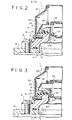
- numeral 1 identifies a pressure regulating device incorporating an embodiment of the invention, which device is mounted atop a transformer tank 3, shown in fragmented section, and having an opening 5 which exposes the contents of the tank, liquid or gas, to the device.
- Device 1 includes a base plate 7, preferably circular in cross-section, which is affixed by fastener means such as machine bolts 9, to the top of the tank 3.
- a gasket 11 may be used to provide a leak tight joint between the device and the tank.
- a circumferential groove 13 is provided for receipt of a seating means in the form of a flat circular gasket 15 having a raised lip portion 17 extending about the inner edge portion of the gasket.
- a plurality of screw and washer assemblies 19 retain the gasket 15 in seated condition in the groove 13.
- a first cup valve 21 is arranged to project into an opening 23 formed in the base plate 7, the upper periphery of the valve resting upon the raised lip portion 17.
- a second cup valve 25, concentrically arranged relative valve 21, is positioned above the first cup valve 21 with the lower outer periphery of valve 25 seated upon the gasket 15.
- Compressively arranged between the cup valves 21 and 25, is a helical spring 27.
- a cover 29 encloses the second cup valve 25, the lower end of the cover being affixed to an outer surface of the base plate 7 by a plurality of screws 31 arranged about the periphery of the base plate.
- the cover 29 has a plurality of openings 33 which provide for a flow of liquid or gasious medium from within the cover 29.
- Compressively arranged between the second cup valve 25 and the cover 29, is a helical spring 35.
- second cup valve 25 is formed with a circular groove, or recess 37 which serves to maintain the springs 27 and 35 in concentric alignment, while the top surface of the cover 29 is formed to stabilize the upper end of the spring 35 against lateral movement.
- Spring 35 must have a greater compressive force than spring 27, so that it will maintain the valve 25 in seated condition upon the gasket 15 until pressure relief action occurs.
- the discharge rate and volume discharge of the tank liquid can be established by proper selection of compressive force of spring 35.
- Initial pressure value to unseat the valve 21 is controlled by the compressive force of spring 27.
- Values of pressure release can be set for any desired figure, a common range for use on power transformers being 0,2812 to 1,4061 kg/cm 2 (4 to 20 p.s.i.g.) which satisfies most operational requirements on such equipment.
- valve 21 In operation the valve 21 is moved upwardly and is unseated (Fig. 2) when the pressure in the tank 3 attains predetermined value, allowing the gas or liquid to flow into the region below the valve 25.
- the pressure of the gas, or liquid involved, is exerted upon the valve 25, which, together with the added lifting force developed by the further compressed spring 27, causes the valve 25 to be unseated (Fig. 3) from the flat gasket 15 whereupon the pressurized medium will be released to atmosphere by way of the opening 33 of the cover 29.
- the spring 35 Once the pressure of the medium returns to a predetermined value, the spring 35 will force the valve 25 to be seated upon the flat gasket 15.
- valve 21 will be reseated upon the gasket lip 17 by action of the spring 27, whereupon the device is returned to initial position (Fig. 1).
- the action of the device to provide a release of gas pressure is extremely rapid, such action being more fully described in the operational theory set forth in patent 3,217,082.
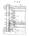
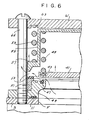
- a second embodiment incorporates certain modification in structure, over that of the first embodiment described above. More particularly, the second embodiment utilizes a disk-like first valve plate 41 having a peripheral groove 43 in which is seated a compression spring 45.
- the valve plate 41 seats upon a valve seating means, namely, a circular gasket 47 positioned in a base plate 49, similar in structure and function to base plate 7 of the first embodiment.
- a valve seat 51 surrounds an upper portion of the base plate 49, and supports a circular gasket 53.
- a second valve 55 which is a cup-like configuration, and concentrically arranged relative the valve 41, engages the gasket 53 and has a peripheral shoulder 57 upon which a compression spring 59 is seated.
- the upper end of the spring 45 abuts the inner surface of the valve 55.
- a top plate 61 is arranged above the valve 55, and has a circumferential recess 63 in which the upper end of the spring 59 is seated.
- a plurality of bolts 65 are arranged to positionally maintain the spring 59, and allow adjustable compression thereof.
- valves 41 and 55 were 148,38 cm 2 (23 sq.in.) and 294,83 cm 2 (45.7 sq.in.) respectively, and springs 45 and 59 had a compressive force of 4,5699 kg/cm 2 (65 lbs/sq.in.) and 5,0621 kg/cm 2 (72 Ibs/sq.in.respectively when compressed 7,62 cm (3 inches).
- springs 45 and 59 had a compressive force of 4,5699 kg/cm 2 (65 lbs/sq.in.) and 5,0621 kg/cm 2 (72 Ibs/sq.in.respectively when compressed 7,62 cm (3 inches).
- Fig. 4 illustrates the non-operative, or closed condition of the device.
- Fig. 5 illustrates the initial stage of operation when the valve 41 is forced off the sealing gasket 47 by reason of fluid pressure within the transformer tank 3 reaching preset unseating pressure.
- Fig. 6 illustrates unseating of the valve 55, by reason of fluid passing valve 41, in which condition the fluid is released to atmosphere, as shown.
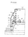
- FIG. 7 incorporates a flat disc valve 69 arranged to seat upon a valve seating means in the form of a circular gasket 71 positioned in a base plate 73, which is mounted atop a transformer tank in the manner of the predescribed embodiments.
- a second valve 75 concentric with valve 69, is arranged to extend about the periphery of the valve 69, an outer region 77 of the valve extending downwardly and in sealing contact with a flexible seal 79 supported in the base plate 73.
- the flexible seal 79 is disclosed and claimed in our copending European patent application No. 82201568.1.
- An inner part 81 of valve 75 extends upwardly adjacent a helical spring 83. The latter is compressively arranged between the valve 75 and a cover 85 affixed to the base plate 73 by screws 87.
- One or more openings 89 are provided in the cover for release of pressure fluid, as will later be described.
- a shield 91 which encircles a helical spring 93 compressively arranged between the valve 69 and the cover 85.
- Spring 93 is stronger compressively than spring 83.
- valve ratio variables and spring rate variables all of which can be arrived at using well known design techniques.
- valve 69 reseating action of the valve 69 is maximized since the more powerful spring 93 is working against a smaller area, compared with the total area of valves 69 and 75. During seating movement the valves will be briefly separated. Fast closing action of the valve 69 serves to reduce fluid e.g., oil, loss in the transformer tank 7.
- Fig. 8 is similar to that of Fig. 7 except for minor design changes, such as a purge valve 95, which is used to allow escape of air in the transformer tank during filling, and an access plate 97 arranged in an opening of a cover 99, and positionally maintained by a plurality of clip means 101.
- the access plate provides access to the purge valve 95.
- Fig. 9 is similar to that of Figs. 7 and 8 except it incorporates a valve 103 which is cup-shaped.
- a second valve 105 seats upon the valve 103, and is concentric therewith, while helical spring 83 is compressively arranged between the valve 105, and a cover 107.
- Spring 93 is compressively arranged between the valve 103 and the shoulder of a sleeve 109.
- An adjusting screw means 111 is arranged in the cover 109 to seat upon the shoulder of the sleeve 109 whereby compressive adjustment of the spring 93 can be achieved.
- Figs. 7, 8 and 9 have basic features in common, namely, both valves used in each embodiment are in physical contact prior to pressure release operation, and the compression springs used in each will operate to reseat the primary, or inner valve, before the outer valve is seated because of area and spring pressure factors, as discussed above.
Landscapes
- Engineering & Computer Science (AREA)
- Power Engineering (AREA)
- Safety Valves (AREA)
- Housings And Mounting Of Transformers (AREA)
Applications Claiming Priority (2)
| Application Number | Priority Date | Filing Date | Title |
|---|---|---|---|
| US37966182A | 1982-05-19 | 1982-05-19 | |
| US379661 | 1982-05-19 |
Publications (1)
| Publication Number | Publication Date |
|---|---|
| EP0094702A1 true EP0094702A1 (fr) | 1983-11-23 |
Family
ID=23498156
Family Applications (1)
| Application Number | Title | Priority Date | Filing Date |
|---|---|---|---|
| EP19830200615 Withdrawn EP0094702A1 (fr) | 1982-05-19 | 1983-04-29 | Dispositif à libération de pression |
Country Status (7)
| Country | Link |
|---|---|
| EP (1) | EP0094702A1 (fr) |
| JP (1) | JPS58211077A (fr) |
| AU (1) | AU1407583A (fr) |
| CA (1) | CA1207213A (fr) |
| DK (1) | DK218883A (fr) |
| ES (1) | ES8407565A1 (fr) |
| PT (1) | PT76723B (fr) |
Cited By (6)
| Publication number | Priority date | Publication date | Assignee | Title |
|---|---|---|---|---|
| EP0200866A1 (fr) | 1985-05-07 | 1986-11-12 | VDO Adolf Schindling AG | Soupape d'injection |
| GB2235038A (en) * | 1989-08-16 | 1991-02-20 | Mueller Co | Dual check valve |
| EP0429447A4 (en) * | 1988-02-05 | 1992-12-30 | Qualitrol Corporation | Gasket assembly and electrical power transformer including the same |
| ES2119720A1 (es) * | 1997-02-10 | 1998-10-01 | Schlumberger Ind Sa | Transformador aislado por gas |
| CN102953120A (zh) * | 2011-08-31 | 2013-03-06 | 上海朗兆机电设备有限公司 | 单晶生长炉压力释放装置 |
| CN110725979A (zh) * | 2019-11-22 | 2020-01-24 | 沈阳明远电气科技有限公司 | 防爆阀 |
Families Citing this family (1)
| Publication number | Priority date | Publication date | Assignee | Title |
|---|---|---|---|---|
| US7210497B2 (en) * | 2003-12-19 | 2007-05-01 | Qualitrol Corporation | Pressure relief device with increased flow rate |
Citations (7)
| Publication number | Priority date | Publication date | Assignee | Title |
|---|---|---|---|---|
| US2904616A (en) * | 1958-03-18 | 1959-09-15 | Mc Graw Edison Co | Encased electrical apparatus having pressure relief means |
| US2989073A (en) * | 1956-05-04 | 1961-06-20 | Bastian Blessing Co | Pressure and vacuum relief valve |
| AT237091B (de) * | 1963-02-01 | 1964-11-25 | Micafil Ag | Expansionsgefäß mit Doppelventil für elektrische Geräte mit flüssigem Dielektrikum |
| US3217082A (en) * | 1962-10-08 | 1965-11-09 | Qualitrol Corp | Snap-action fault protector for electrical apparatus |
| DE2301590A1 (de) * | 1972-01-20 | 1973-07-26 | Qualitrol Corp | Druckentlastungsventil |
| US3914528A (en) * | 1974-03-20 | 1975-10-21 | Qualitrol Corp | Pressure relief device for power transformer |
| EP0083814A1 (fr) * | 1982-01-07 | 1983-07-20 | Qualitrol Corporation | Dispositif à libération de pression |
-
1983
- 1983-04-28 CA CA000426952A patent/CA1207213A/fr not_active Expired
- 1983-04-29 EP EP19830200615 patent/EP0094702A1/fr not_active Withdrawn
- 1983-04-29 AU AU14075/83A patent/AU1407583A/en not_active Abandoned
- 1983-05-17 DK DK218883A patent/DK218883A/da not_active Application Discontinuation
- 1983-05-18 PT PT7672383A patent/PT76723B/pt unknown
- 1983-05-18 ES ES522505A patent/ES8407565A1/es not_active Expired
- 1983-05-19 JP JP8834383A patent/JPS58211077A/ja active Pending
Patent Citations (7)
| Publication number | Priority date | Publication date | Assignee | Title |
|---|---|---|---|---|
| US2989073A (en) * | 1956-05-04 | 1961-06-20 | Bastian Blessing Co | Pressure and vacuum relief valve |
| US2904616A (en) * | 1958-03-18 | 1959-09-15 | Mc Graw Edison Co | Encased electrical apparatus having pressure relief means |
| US3217082A (en) * | 1962-10-08 | 1965-11-09 | Qualitrol Corp | Snap-action fault protector for electrical apparatus |
| AT237091B (de) * | 1963-02-01 | 1964-11-25 | Micafil Ag | Expansionsgefäß mit Doppelventil für elektrische Geräte mit flüssigem Dielektrikum |
| DE2301590A1 (de) * | 1972-01-20 | 1973-07-26 | Qualitrol Corp | Druckentlastungsventil |
| US3914528A (en) * | 1974-03-20 | 1975-10-21 | Qualitrol Corp | Pressure relief device for power transformer |
| EP0083814A1 (fr) * | 1982-01-07 | 1983-07-20 | Qualitrol Corporation | Dispositif à libération de pression |
Cited By (10)
| Publication number | Priority date | Publication date | Assignee | Title |
|---|---|---|---|---|
| EP0200866A1 (fr) | 1985-05-07 | 1986-11-12 | VDO Adolf Schindling AG | Soupape d'injection |
| EP0200866B1 (fr) * | 1985-05-07 | 1988-08-03 | VDO Adolf Schindling AG | Soupape d'injection |
| EP0429447A4 (en) * | 1988-02-05 | 1992-12-30 | Qualitrol Corporation | Gasket assembly and electrical power transformer including the same |
| GR890100063A (el) * | 1988-02-05 | 1994-03-31 | Qualitrol Corp | Διάταξη συναρμολογήσεως παρεμβύσματος. |
| GB2235038A (en) * | 1989-08-16 | 1991-02-20 | Mueller Co | Dual check valve |
| GB2235038B (en) * | 1989-08-16 | 1992-12-23 | Mueller Co | Dual check valve |
| ES2119720A1 (es) * | 1997-02-10 | 1998-10-01 | Schlumberger Ind Sa | Transformador aislado por gas |
| CN102953120A (zh) * | 2011-08-31 | 2013-03-06 | 上海朗兆机电设备有限公司 | 单晶生长炉压力释放装置 |
| CN102953120B (zh) * | 2011-08-31 | 2015-08-12 | 上海朗兆机电设备有限公司 | 单晶生长炉压力释放装置 |
| CN110725979A (zh) * | 2019-11-22 | 2020-01-24 | 沈阳明远电气科技有限公司 | 防爆阀 |
Also Published As
| Publication number | Publication date |
|---|---|
| ES522505A0 (es) | 1984-09-16 |
| CA1207213A (fr) | 1986-07-08 |
| DK218883D0 (da) | 1983-05-17 |
| JPS58211077A (ja) | 1983-12-08 |
| AU1407583A (en) | 1983-11-24 |
| PT76723A (en) | 1983-06-01 |
| ES8407565A1 (es) | 1984-09-16 |
| DK218883A (da) | 1983-11-20 |
| PT76723B (en) | 1986-05-07 |
Similar Documents
| Publication | Publication Date | Title |
|---|---|---|
| US2573522A (en) | Valve with vibration damper | |
| EP0094702A1 (fr) | Dispositif à libération de pression | |
| US2239169A (en) | Safety valve | |
| KR100604444B1 (ko) | 탱크 수송용 압력 릴리이프 밸브 조립체 | |
| JPH04506992A (ja) | 通気孔と過圧弁との組立体 | |
| CA2034942A1 (fr) | Capsule de gaz propulseur pour bombe aerosol et bombe aerosol faisant appel a ladite capsule | |
| US3982729A (en) | Back-up seal for diaphragm valve | |
| US5240027A (en) | Combination relief vent and closure apparatus | |
| US4068680A (en) | Self-contained vent valve unit and system utilizing the same | |
| US3421546A (en) | Pressure release valve | |
| US4848729A (en) | Valve seal | |
| GB2095371A (en) | Pressure relief device | |
| US4809740A (en) | Excess flow limiter | |
| KR950006290A (ko) | 밸브 장치 | |
| CA2550098C (fr) | Dispositif de decompression a debit augmente | |
| US5234023A (en) | Pressure relief valve with auxiliary loading device | |
| US6629621B1 (en) | Gauge hatch with liquid seal | |
| US3502361A (en) | Magnetically biased tank vent | |
| KR102020203B1 (ko) | 터보 송풍기 설치용 블로우 오프 밸브 | |
| KR20050024440A (ko) | 서지 방지 장치 | |
| US3273852A (en) | Ball valve construction | |
| US3155357A (en) | Leveling device | |
| US2880782A (en) | Pneumatic seat | |
| US4951918A (en) | Valve vent | |
| US2837110A (en) | Fluid pressure control valve |
Legal Events
| Date | Code | Title | Description |
|---|---|---|---|
| PUAI | Public reference made under article 153(3) epc to a published international application that has entered the european phase |
Free format text: ORIGINAL CODE: 0009012 |
|
| AK | Designated contracting states |
Designated state(s): AT BE CH DE FR GB IT LI LU NL SE |
|
| 17P | Request for examination filed |
Effective date: 19840508 |
|
| STAA | Information on the status of an ep patent application or granted ep patent |
Free format text: STATUS: THE APPLICATION IS DEEMED TO BE WITHDRAWN |
|
| 18D | Application deemed to be withdrawn |
Effective date: 19860122 |
|
| RIN1 | Information on inventor provided before grant (corrected) |
Inventor name: JOHNSON, WENDELL DAVID |