EP0094706A2 - Analyseur de gaz - Google Patents
Analyseur de gaz Download PDFInfo
- Publication number
- EP0094706A2 EP0094706A2 EP83200629A EP83200629A EP0094706A2 EP 0094706 A2 EP0094706 A2 EP 0094706A2 EP 83200629 A EP83200629 A EP 83200629A EP 83200629 A EP83200629 A EP 83200629A EP 0094706 A2 EP0094706 A2 EP 0094706A2
- Authority
- EP
- European Patent Office
- Prior art keywords
- gas
- radiation
- detectors
- sited
- source
- Prior art date
- Legal status (The legal status is an assumption and is not a legal conclusion. Google has not performed a legal analysis and makes no representation as to the accuracy of the status listed.)
- Withdrawn
Links
Images
Classifications
-
- G—PHYSICS
- G01—MEASURING; TESTING
- G01N—INVESTIGATING OR ANALYSING MATERIALS BY DETERMINING THEIR CHEMICAL OR PHYSICAL PROPERTIES
- G01N21/00—Investigating or analysing materials by the use of optical means, i.e. using sub-millimetre waves, infrared, visible or ultraviolet light
- G01N21/17—Systems in which incident light is modified in accordance with the properties of the material investigated
- G01N21/25—Colour; Spectral properties, i.e. comparison of effect of material on the light at two or more different wavelengths or wavelength bands
- G01N21/31—Investigating relative effect of material at wavelengths characteristic of specific elements or molecules, e.g. atomic absorption spectrometry
- G01N21/35—Investigating relative effect of material at wavelengths characteristic of specific elements or molecules, e.g. atomic absorption spectrometry using infrared light
- G01N21/3504—Investigating relative effect of material at wavelengths characteristic of specific elements or molecules, e.g. atomic absorption spectrometry using infrared light for analysing gases, e.g. multi-gas analysis
-
- G—PHYSICS
- G01—MEASURING; TESTING
- G01J—MEASUREMENT OF INTENSITY, VELOCITY, SPECTRAL CONTENT, POLARISATION, PHASE OR PULSE CHARACTERISTICS OF INFRARED, VISIBLE OR ULTRAVIOLET LIGHT; COLORIMETRY; RADIATION PYROMETRY
- G01J1/00—Photometry, e.g. photographic exposure meter
- G01J1/10—Photometry, e.g. photographic exposure meter by comparison with reference light or electric value provisionally void
- G01J1/16—Photometry, e.g. photographic exposure meter by comparison with reference light or electric value provisionally void using electric radiation detectors
- G01J1/1626—Arrangements with two photodetectors, the signals of which are compared
-
- G—PHYSICS
- G01—MEASURING; TESTING
- G01N—INVESTIGATING OR ANALYSING MATERIALS BY DETERMINING THEIR CHEMICAL OR PHYSICAL PROPERTIES
- G01N21/00—Investigating or analysing materials by the use of optical means, i.e. using sub-millimetre waves, infrared, visible or ultraviolet light
- G01N21/17—Systems in which incident light is modified in accordance with the properties of the material investigated
- G01N21/25—Colour; Spectral properties, i.e. comparison of effect of material on the light at two or more different wavelengths or wavelength bands
- G01N21/31—Investigating relative effect of material at wavelengths characteristic of specific elements or molecules, e.g. atomic absorption spectrometry
- G01N21/314—Investigating relative effect of material at wavelengths characteristic of specific elements or molecules, e.g. atomic absorption spectrometry with comparison of measurements at specific and non-specific wavelengths
-
- G—PHYSICS
- G01—MEASURING; TESTING
- G01N—INVESTIGATING OR ANALYSING MATERIALS BY DETERMINING THEIR CHEMICAL OR PHYSICAL PROPERTIES
- G01N2201/00—Features of devices classified in G01N21/00
- G01N2201/12—Circuits of general importance; Signal processing
- G01N2201/127—Calibration; base line adjustment; drift compensation
Definitions
- This invention relates to gas analysers, and is particularly, though not necessarily exclusively, concerned with the analysis of the carbon monoxide content of flue gas.
- infra-red radiation from a suitable source is directed through the gas to be analysed on to a suitably responsive detector, and a known sample of the gas, having the same basic absorption characteristics as the gas under observation, is alternately placed into and removed from the optical path of the infra-red radiation at a desired frequency.
- the difference in dete.ctor out puts, with and without the known gas sample in the optical path, can be shown to be dependent upon the concentration of the gas under analysis, and the instrument can be calibrated accordingly.
- One method of overcoming this problem is to use a beam splitter to produce two optical paths after the radiation has passed through the gas to be analysed.
- One beam then passes through the further known sample where it is measured by a detector, the other beam being measured directly by a second detector.
- the difference in detector outputs is then again related to the concentration of the gas in the sample to be analysed. Whilst the measurement is made without moving parts, the problem for such an instrument is its extreme vulnerability to detector drift. Since two detectors are used instead of one any drift in either of them will produce errors in measurement of gas concentration, with the adverse effect this has on attempting to achieve an optimum air/fuel ratio.
- the object of the invention is to provide a means of gas analysis utilising a beam splitter, that allows simple and yet rapid and effective checking for any detector drift.
- a gas analyser comprises a s.ource of infra-red radiation adapted to be sited to one side of a gas passageway, a collecting lens adapted to be sited at the opposite side of the gas passageway, two detectors on to which infra-red radiation is to be.
- a beam splitter sited between the lens and the detectors and either a gas cell, said gas cell containing a sample of gas being analysed, or an equivalent means sited between the beam splitter and the first detector, and there being adapted to be positioned in the path between the radiation source and each detector a band-pass filter to transmit radiation in a wave band absorbed by the gas under analysis together with means to eliminate the part of the said radiation specifically absorbed by the said gas in that wave band adapted to be positioned periodically in the path between the radiation source and the detectors in addition to or in place of the band-pass filter.
- a gas analyser comprises a source of infra-red radiation adapted to be sited to one side of a gas passageway, a collecting lens adapted to be sited at the opposite side of the gas passageway, two .detectors on to which infra-red radiation is to be focussed, a beam splitter sited between the lens and the detectors, and a gas cell between the beam splitter and one detector, said gas cell containing a sample of gas being analysed or an equivalent filter means, there being selectively provided in the path between the radiation source and the beam splitter two band-' pass filters, one to transmit radiation in a waveband absorbed by the gas under analysis, and the other to transmit radiation in a second waveband not absorbed by the gas under analysis.
- the radiation from the source may if desired be chopped to produce radiation, the magnitude of which varies with time.
- the means to eliminate radiation in a wave band absorbed by the gas under analysis may be a second gas c.ell containing a sample of gas being analysed.
- a gas analyser comprises a source of infra-red radiation adapted to be sited to one side of a gas passageway, a collecting lens adapted to be sited at the opposite side of the gas passageway, two detectors on to which infra-red radiation is to be focussed, a beam splitter sited between the lens and the detectors, and a gas cell between the beam splitter and one detector, said gas cell containing a sample of gas being analysed, there-being provided in the path between the radiation source and the or each detector a band-pass filter to transmit radiation in a wave band absorbed by the gas under analysis, and there being a second gas cell containing a.
- the second gas cell may be positioned between the source and the collecting lens.
- a second collecting lens is provided to the same side of the gas passageway as the source, to focus radiation on to the collecting lens to the opposite side of the gas passageway.
- the radiation from the source may if desired be chopped to produce radiation, the magnitude of which varies with time.
- the gas in the passageway is constantly monitored with the band-pass filter transmitting radiation in a wavelength absorbed by the gas under analysis, the outputs from the two detectors being, compared, and the difference utilised to compute in relatively known manner the concentration of the gas being analysed in the gas flow in the passageway.
- the'second band-pass filter is introduced in place of the first filter, or the second gas cell introduced when both detectors are irradiated with radiation at wavelengths not significantly further absorbed by the gas under analysis and when the two detectors see the source of radiation.affected to the same degree. Any difference in detector output then immediately signifies that there has been detector drift and when immediate corrective action can be taken.
- the invention therefore provides a gas analyser that avoids, in simple manner, the problems of repeated introduction into a radiation path one or more reference cells by utilising a two detector system, and allows the rapid monitoring of the degree of calibration between the two detectors.
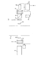
- a radiation source e.g., a hot plate or glow bar 1 is provided to one side of . a passageway 2 for flue gas containing a quantity of carbon monoxide.
- a collecting lens 3 is provided, to focus radiation on to a collecting lens 4 to the opposite side of the gas passageway, and beyond which is a band-pass filter 5, followed by a beam splitter 6 allowing e.g., 50% of the radiation to pass straight through to a reference cell 7 containing a sample of carbon monoxide behind which is a detector 8, and diverting, e.g.-, 50% through 90° to reach a detector 9.
- the outputs from the detectors 8 and 9 are fed to a signal processor 10, either to compute the concentration of carbon monoxide in the gas in the passageway or to compute the degree of calibration between the two detectors.
- the band-pass filter 5 is provided in the radiation path, which filter transmits radiation in the wavelength absorbed by carbon monoxide.
- the different outputs from the detectors are then used in known manner to compute the carbon monoxide concentration.
- a second gas cell 11 is introduced between the radiation source and the filter 5, the second gas cell containing a sample of carbon' monoxide.
- the second gas cell is in place, substantially all radiation in the wave length absorbed by carbon monoxide is absorbed and when the outputs from the detectors 8, 9 are unaffected by the minimal (comparatively) further absorption of radiation by any carbon. monoxide content of the gas passing through the passageway 2.
- any difference in output from the detectors 8, 9 signifies that there has been detector drift and again immediate corrective action can be taken.
- a second band pass filter indicated at 12 can be used in place of the gas cell 11.
- the second band pass filter can, periodically, replace the band pass filter 5, and with the filter 12 allowing the transmission of radiation in a waveband not absorbed by the gas under analysis, the same effect is achieved, i.e. the two detectors are unaffected by any radiation absorption in the gas passageway, and any difference in output signifies detector drift.
Landscapes
- Physics & Mathematics (AREA)
- Spectroscopy & Molecular Physics (AREA)
- Health & Medical Sciences (AREA)
- Life Sciences & Earth Sciences (AREA)
- Chemical & Material Sciences (AREA)
- Analytical Chemistry (AREA)
- Biochemistry (AREA)
- General Health & Medical Sciences (AREA)
- General Physics & Mathematics (AREA)
- Immunology (AREA)
- Pathology (AREA)
- Investigating Or Analysing Materials By Optical Means (AREA)
- Spectrometry And Color Measurement (AREA)
Applications Claiming Priority (2)
| Application Number | Priority Date | Filing Date | Title |
|---|---|---|---|
| GB8214151 | 1982-05-14 | ||
| GB8214151 | 1982-05-14 |
Publications (2)
| Publication Number | Publication Date |
|---|---|
| EP0094706A2 true EP0094706A2 (fr) | 1983-11-23 |
| EP0094706A3 EP0094706A3 (fr) | 1984-08-01 |
Family
ID=10530370
Family Applications (1)
| Application Number | Title | Priority Date | Filing Date |
|---|---|---|---|
| EP83200629A Withdrawn EP0094706A3 (fr) | 1982-05-14 | 1983-05-03 | Analyseur de gaz |
Country Status (2)
| Country | Link |
|---|---|
| EP (1) | EP0094706A3 (fr) |
| JP (1) | JPS5946522A (fr) |
Cited By (5)
| Publication number | Priority date | Publication date | Assignee | Title |
|---|---|---|---|---|
| GB2226401A (en) * | 1988-12-13 | 1990-06-27 | Robin John Hutchinson | Gas analysis apparatus |
| EP0379891A3 (fr) * | 1989-01-25 | 1991-04-10 | Baldwin-Gegenheimer GmbH | Séchoir pour presses à bobines et son procédé de fonctionnement |
| EP1916513A1 (fr) | 2006-10-27 | 2008-04-30 | optek-Danulat GmbH | Dispositif photométrique en ligne et procédé de calibrage |
| WO2008049484A1 (fr) * | 2006-10-27 | 2008-05-02 | Optek-Danulat Gmbh | Dispositif photométrique en ligne et procédé d'étalonnage |
| WO2021048771A1 (fr) | 2019-09-13 | 2021-03-18 | Forbes Marshall Private Limited | Système d'analyse de gaz in situ |
Family Cites Families (3)
| Publication number | Priority date | Publication date | Assignee | Title |
|---|---|---|---|---|
| US2534657A (en) * | 1948-08-07 | 1950-12-19 | Socony Vacuum Oil Co Inc | Monochromator |
| US3807876A (en) * | 1972-03-15 | 1974-04-30 | Mitsubishi Electric Corp | Gas densitometer |
| US3811776A (en) * | 1973-02-26 | 1974-05-21 | Environmental Res & Tech | Gas analyzer |
-
1983
- 1983-05-03 EP EP83200629A patent/EP0094706A3/fr not_active Withdrawn
- 1983-05-13 JP JP8397583A patent/JPS5946522A/ja active Pending
Cited By (7)
| Publication number | Priority date | Publication date | Assignee | Title |
|---|---|---|---|---|
| GB2226401A (en) * | 1988-12-13 | 1990-06-27 | Robin John Hutchinson | Gas analysis apparatus |
| GB2226401B (en) * | 1988-12-13 | 1992-11-25 | Robin John Hutchinson | Gas analysis |
| EP0379891A3 (fr) * | 1989-01-25 | 1991-04-10 | Baldwin-Gegenheimer GmbH | Séchoir pour presses à bobines et son procédé de fonctionnement |
| EP1916513A1 (fr) | 2006-10-27 | 2008-04-30 | optek-Danulat GmbH | Dispositif photométrique en ligne et procédé de calibrage |
| WO2008049484A1 (fr) * | 2006-10-27 | 2008-05-02 | Optek-Danulat Gmbh | Dispositif photométrique en ligne et procédé d'étalonnage |
| WO2021048771A1 (fr) | 2019-09-13 | 2021-03-18 | Forbes Marshall Private Limited | Système d'analyse de gaz in situ |
| EP4028749A4 (fr) * | 2019-09-13 | 2023-01-11 | Forbes Marshall Private Limited | Système d'analyse de gaz in situ |
Also Published As
| Publication number | Publication date |
|---|---|
| EP0094706A3 (fr) | 1984-08-01 |
| JPS5946522A (ja) | 1984-03-15 |
Similar Documents
| Publication | Publication Date | Title |
|---|---|---|
| EP0386125B1 (fr) | Analyseur de gaz a double cellule d'echantillon | |
| CN101718670B (zh) | 烟气颗粒物和污染气体同时在线监测装置和方法 | |
| US3994590A (en) | Discrete frequency colorimeter | |
| CA1254281A (fr) | Methode et appareil de detection et de mesure des concentrations de gaz | |
| US4669878A (en) | Automatic monochromator-testing system | |
| EP1693665B1 (fr) | Procédé et dispositif pour détecter des gaz à l'état de traces | |
| US6044332A (en) | Surface acoustic wave harmonic analysis | |
| US4736103A (en) | Spectrometer test gas chamber | |
| US4516858A (en) | Multiple site laser excited pollution monitoring system | |
| EP2341338A1 (fr) | Dispositif de mesure de l'opacité des gaz d'échappement | |
| US4471220A (en) | System for monitoring trace gaseous ammonia concentration in flue gases | |
| US4630923A (en) | Fiberoptic spectrophotometer | |
| US6762410B1 (en) | Analysis apparatus | |
| EP0121404A2 (fr) | Appareil photométrique pour la mesure de l'absorption lumineuse | |
| US20030132389A1 (en) | Method for monitoring and controlling the high temperature reducing combustion atmosphere | |
| US4297577A (en) | Radiation detection of gas compositions | |
| US20030120434A1 (en) | Exhaust opacity measuring device | |
| US3193676A (en) | Infra-red gas analysers | |
| US3013466A (en) | Turbidity measuring instrument | |
| CA1247398A (fr) | Systeme automatique d'analyse chimique a faisceau lumineux monochromatique | |
| US4501968A (en) | Infrared radiation gas analyzer | |
| JPS58156837A (ja) | 光学式ガス分析用測定装置 | |
| EP4276444B1 (fr) | Dispositif de mesure de concentration de co2 optique basé sur l'absorption de lumière infrarouge dans un gaz | |
| DE4437188C2 (de) | Analysengerät zur Konzentrationsbestimmung | |
| GB2035552A (en) | Radiation detection of gas compositions |
Legal Events
| Date | Code | Title | Description |
|---|---|---|---|
| PUAI | Public reference made under article 153(3) epc to a published international application that has entered the european phase |
Free format text: ORIGINAL CODE: 0009012 |
|
| AK | Designated contracting states |
Designated state(s): AT BE CH DE FR GB IT LI LU NL SE |
|
| PUAL | Search report despatched |
Free format text: ORIGINAL CODE: 0009013 |
|
| AK | Designated contracting states |
Designated state(s): AT BE CH DE FR GB IT LI LU NL SE |
|
| 17P | Request for examination filed |
Effective date: 19850118 |
|
| 17Q | First examination report despatched |
Effective date: 19860407 |
|
| STAA | Information on the status of an ep patent application or granted ep patent |
Free format text: STATUS: THE APPLICATION IS DEEMED TO BE WITHDRAWN |
|
| 18D | Application deemed to be withdrawn |
Effective date: 19860819 |
|
| RIN1 | Information on inventor provided before grant (corrected) |
Inventor name: COE, CHARLES DAVID |