EP0094710B1 - Vorrichtung zum optischen Einkoppeln - Google Patents
Vorrichtung zum optischen Einkoppeln Download PDFInfo
- Publication number
- EP0094710B1 EP0094710B1 EP83200652A EP83200652A EP0094710B1 EP 0094710 B1 EP0094710 B1 EP 0094710B1 EP 83200652 A EP83200652 A EP 83200652A EP 83200652 A EP83200652 A EP 83200652A EP 0094710 B1 EP0094710 B1 EP 0094710B1
- Authority
- EP
- European Patent Office
- Prior art keywords
- light
- transparent body
- transmitter
- fibre
- receiving element
- Prior art date
- Legal status (The legal status is an assumption and is not a legal conclusion. Google has not performed a legal analysis and makes no representation as to the accuracy of the status listed.)
- Expired
Links
- 230000008878 coupling Effects 0.000 title claims description 35
- 238000010168 coupling process Methods 0.000 title claims description 35
- 238000005859 coupling reaction Methods 0.000 title claims description 35
- 230000003287 optical effect Effects 0.000 title claims description 18
- 239000000835 fiber Substances 0.000 claims description 41
- 238000012634 optical imaging Methods 0.000 claims description 3
- 239000002184 metal Substances 0.000 description 4
- 238000010276 construction Methods 0.000 description 2
- 239000011521 glass Substances 0.000 description 2
- 239000000853 adhesive Substances 0.000 description 1
- 230000001070 adhesive effect Effects 0.000 description 1
- 239000004568 cement Substances 0.000 description 1
- 238000003384 imaging method Methods 0.000 description 1
- 239000007788 liquid Substances 0.000 description 1
- 229920003217 poly(methylsilsesquioxane) Polymers 0.000 description 1
- 239000004065 semiconductor Substances 0.000 description 1
- 229920003002 synthetic resin Polymers 0.000 description 1
- 239000000057 synthetic resin Substances 0.000 description 1
Images
Classifications
-
- G—PHYSICS
- G02—OPTICS
- G02B—OPTICAL ELEMENTS, SYSTEMS OR APPARATUS
- G02B6/00—Light guides; Structural details of arrangements comprising light guides and other optical elements, e.g. couplings
- G02B6/24—Coupling light guides
- G02B6/42—Coupling light guides with opto-electronic elements
- G02B6/4201—Packages, e.g. shape, construction, internal or external details
- G02B6/4204—Packages, e.g. shape, construction, internal or external details the coupling comprising intermediate optical elements, e.g. lenses, holograms
- G02B6/4206—Optical features
-
- G—PHYSICS
- G02—OPTICS
- G02B—OPTICAL ELEMENTS, SYSTEMS OR APPARATUS
- G02B6/00—Light guides; Structural details of arrangements comprising light guides and other optical elements, e.g. couplings
- G02B6/24—Coupling light guides
- G02B6/26—Optical coupling means
- G02B6/32—Optical coupling means having lens focusing means positioned between opposed fibre ends
-
- G—PHYSICS
- G02—OPTICS
- G02B—OPTICAL ELEMENTS, SYSTEMS OR APPARATUS
- G02B6/00—Light guides; Structural details of arrangements comprising light guides and other optical elements, e.g. couplings
- G02B6/24—Coupling light guides
- G02B6/42—Coupling light guides with opto-electronic elements
- G02B6/4201—Packages, e.g. shape, construction, internal or external details
- G02B6/4246—Bidirectionally operating package structures
-
- G—PHYSICS
- G02—OPTICS
- G02B—OPTICAL ELEMENTS, SYSTEMS OR APPARATUS
- G02B6/00—Light guides; Structural details of arrangements comprising light guides and other optical elements, e.g. couplings
- G02B6/24—Coupling light guides
- G02B6/42—Coupling light guides with opto-electronic elements
- G02B6/4292—Coupling light guides with opto-electronic elements the light guide being disconnectable from the opto-electronic element, e.g. mutually self aligning arrangements
Definitions
- the invention relates to an optical coupling device for coupling an end of a light-conducting fibre to an optical transmitter device and an optical receiver device, the receiver device comprising a light-receiving element arranged opposite an end face of the fibre end and provided with an opening, a front side of said element facing the fibre end, the transmitter devic e comprising a transmitter element located on the back side of the lightcollecting element remote from the fibre end opposite the opening along with a transmitter lens designed to focus light emitted by the transmitter element towards the end face of the fibre end.
- Such a device is known from The Bell System Technical Journal, 58, no. 7 (September 1979), pp. 17351741.
- the known coupling device comprises a comparatively large number of optical components, which have to be aligned accurately with respect to each other. As a result, the operation of mounting this coupling device is timeconsuming and expensive.
- the invention has for its object to provide a coupling device which has a comparatively simple construction and can be rapidly and readily manufactured as compared with the known coupling device.
- the coupling device is therefore characterized in that between the end face of the fibre end and the front side of the light-receiving element there is arranged a transparent body optically coupled to the fibre end, the light-receiving element and the transmitter element said transparent body having side faces and at least part of each side face is reflecting, the arrangement being such that substantially all the light emanating from the fibre end strikes the light-receiving element.
- the transparent body may be, for example, a cylindrical glass rod, the cylindrical surface of which is coated with a reflective layer so that the light emanating from the fibre end invariably impinges on the lightreceiving element without it being necessary for the parts to be aligned accurately with respect to each other. Only the transmitter lens should be positioned so that the light emitted by the transmitter element is focussed onto the end face of the fibre end.
- the transmitter element is coupled to the transparent body by means of a detachable coupling comprising a first plug part with a first ball lens serving as the transmitter lens, which first plug part can be detachably secured in a plug holder rigidly connected to the transparent body.
- the detachable coupling can be of a type known per se, as described, for example, in the Dutch patent Application no. 79 05 610 (PHN 9537).
- the alignment is then effected by means of the precedure usual for these couplings.
- a further preferred embodiment of the coupling device according to the invention is characterized in that the end of the light-conducting fibre is coupled to the transparent body by means of a detachable coupling comprising a second plug part with a second ball lens, which second plug part can be detachably secured in a plug holder rigidly connected to the transparent body and accommodating a third ball lens which, when the second plug part is connected to the plug holder, constitutes together with the second ball lens an optical imaging system designed for imaging approximately to scale the end face of the fibre end on a front face of the transparent body.
- This embodiment can be very readily attached and detached.
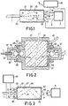
- the optical coupling device shown diagrammatically in Figure 1 serves to couple an end 1 of a light- ⁇ conducting fibre to both an optical transmitter device 3 and an optical receiver device 5.
- the transmitter device 3 comprises a transmitter element 7, for example in the form of a semiconductor laser, as well as a transmitter lens 9.
- the transmitter element 7 is controlled by a transmitter circuit 1 1 and then emits light which is focussed by the transmitter lens 9 onto an end face 13 of the fibre end 1.
- the light beam travelling from the transmitter element 7 to the end face 1 3 is indicated by dotted lines 15.
- the receiver device 5 comprises a light-receiving element 17 arranged opposite the end face 13 of the fibre end 1, provided with an opening 19 and electrically connected to a receiver circuit 20.
- the front side of the light- receiving element 17 (in Figure 1 the lefthand side) faces the fibre end 1.
- the transmitter lens 9 and the transmitter element 7 are located on the rear side of the light-receiving element 17 opposite the opening 19.
- the light-receiving element 17 is constituted by a number of photosensitive elements, for example photosensitive diodes. If desired, it may also consist of a single photosensitive element with a central opening 19.
- the light-receiving element 17 extends in a plane at right angles to the longitudinal axis of the fibre end 1. However, it may also enclose an angle with this axis or may be curved so as to take the form of a cup with the concave side facing the fibre end 1.
- a transparent body 21 which is optically coupled on its front side (lefthand side in Figure 1) to the fibre end 1 by the end face 13 of the fibre end engaging the front surface 23 of the body, for example, with the addition of a suitable adhesive or a coupling liquid.
- the transparent body 21 is optically coupled to the front side of the light-receivin element 17 and to the transmitter element 7.
- the photosensitive elements constituting the light-receiving element are secured against the rear surface 25 of the transparent body, for example, with a suitable cement.
- the transmitter element 7 is coupled through the transmitter lens 9 and the opening 19 to the transparent body 21.
- the side faces 27 of this body are made reflective, for example, by the application of a metal layer 29.
- the body 21 may consist, for example, of a rod of glass or synthetic resin in the form of a cylinder or a prism. Due to the fact that the side faces 27 are reflective, substantially all the light emanating from the fibre end 1 is conducted to the light-receiving element 17. By way of example, the paths of two light beams 31 are indicated in dotted lines. Since the light emanates at a limited angle to the axis of the fibre end 1, it cannot strike the parts of the side faces 27 located in the immediate proximity of the front surface 23. Thus, it is not absolutely necessary for the reflective layer 29 to extend as far as the front surface 23.
- the only light that is lost when striking the light-receiving element 17 is the light which is incident upon the opening 19 provided in the light-receiving element.
- this loss can be reduced to a very small percentage.
- FIG. 2 is a longitudinal sectional view of a second embodiment, in which a larger number of constructional details are visible.
- the parts corresponding to parts of the embodiment shown in Figure 1 are denoted by the same reference numerals as in Figure 1.
- the transparent body 21 is secured in this embodiment in a metal housing 33, on the rear side of which (righthand side in Figure 2) a first annular plug holder 35 is formed.
- This plug holder constitutes together with a first plug part 37 a first detachable coupling.
- the first plug part 37 comprises radially projecting pins 39, which constitute together with L-shaped slots in the plug holder 35 a highspeed bayonette coupling.
- the first plug part 37 accommodates the transmitter element 7 and a first ball lens constituting the transmitter lens 9.
- the transmitter element is connected through a cable 41 to the transmitter circuit 11 ( see Figure 1).
- the parts 35,37 of the detachable coupling are manufactured according to the design of a known ball lens coupling.
- a large number of such couplings are known; see, for example, the Dutch Patent Application nos. 78 06 829 (PHN 9163) and 79 05 610 (PHN 9537).
- the constructional details will not be described further herein. It should only be noted that, as far as the known couplings are adapted to couple light-conducting fibres, in the present case the transmitter element 7 takes the place of the end of the light-conducting fibre.
- the light-collecting element 17 is situated between the rear wall of the housing 33 and the rear surface 25 of the transparent body 21. It is connected through a cable 43 to the receiver circuit 20 (see Figure 1).
- a second annular plug holder 45 On the front side of the housing 33 (the lefthand side in Fignre 2) there is formed a second annular plug holder 45, which constitutes together with a second plug part 47 a second detachable coupling.
- the second plug part 47 comprises radially projecting pins 49, which constitute together with L-shaped slots in the plug holder 45 a highspeed bayonette coupling.
- the second plug part 47 accommodates the fibre end 1 secured in the fibre holder 51.
- the second plug part 47 comprises a second ball lens 53 and completely corresponds to known plug parts.
- a third ball lens 55 which constitutes together with the second ball lens 53 an optical imaging system, which images the end face 13 approximately to scale on the front surface 23 of the transparent body 21. Due to this construction, the connection between the fibre end 1 and the transparent body 21 can be rapidly and readily established and interrupted and a satisfactory optical coupling between the fibre end and the transparent body is guaranteed.
- Figure 3 shows in the same manner as Figure 1 diagrammatically a third embodiment, in which corresponding parts are again denoted by the same reference numerals.
- the light-receiving element is constituted by the rear surface 25 of the transparent body 21.
- the rear surface s made reflective by the application of a reflecting metal layer 57, which can be provided simultaneously with the metal layer 29 on the side face 27.
- the reflecting layer 57 is provided with an opening 59 which has the same function as the opening 19 in the light-receiving element 17 shown in Figure 1.
- a light beam 61 emanating from the fibre end 1 through the ball lenses 53,55 (cf. Figure 2) reaches after one or more reflections on the side face 27 the rear surface 25 and, unless it strikes the opening 59, is then reflected back towards the front surface 23 at which it arrives after optionally having been reflected again a few times by the side face 27.
- One or more photosensitive elements 63 are secured against the front surface 23, an opening 65 being provided for passing the light travelling from the fibre end to the transparent body 21.
- the light beam 61 strikes, unless it is incident upon the opening 65, the photosensitive element 63, which is electrically connected to the receiver circuit 20.
- optical coupling device may be used, for example, in a transmitter/receiver device for communication in two directions.
- energy is supplied through the light-conducting fibre in the form of light, which energy is converted in the receiver circuit into electrical energy for feeding the transmitter circuit, as a result of which the latter can operate independently of local energy sources.
Landscapes
- Physics & Mathematics (AREA)
- General Physics & Mathematics (AREA)
- Optics & Photonics (AREA)
- Optical Couplings Of Light Guides (AREA)
- Optical Communication System (AREA)
Claims (5)
Applications Claiming Priority (2)
| Application Number | Priority Date | Filing Date | Title |
|---|---|---|---|
| NL8202008 | 1982-05-14 | ||
| NL8202008A NL8202008A (nl) | 1982-05-14 | 1982-05-14 | Optische koppelinrichting. |
Publications (2)
| Publication Number | Publication Date |
|---|---|
| EP0094710A1 EP0094710A1 (de) | 1983-11-23 |
| EP0094710B1 true EP0094710B1 (de) | 1986-02-05 |
Family
ID=19839742
Family Applications (1)
| Application Number | Title | Priority Date | Filing Date |
|---|---|---|---|
| EP83200652A Expired EP0094710B1 (de) | 1982-05-14 | 1983-05-06 | Vorrichtung zum optischen Einkoppeln |
Country Status (6)
| Country | Link |
|---|---|
| US (1) | US4753508A (de) |
| EP (1) | EP0094710B1 (de) |
| JP (1) | JPS58208716A (de) |
| CA (1) | CA1242908A (de) |
| DE (1) | DE3362066D1 (de) |
| NL (1) | NL8202008A (de) |
Families Citing this family (24)
| Publication number | Priority date | Publication date | Assignee | Title |
|---|---|---|---|---|
| NL8202008A (nl) * | 1982-05-14 | 1983-12-01 | Philips Nv | Optische koppelinrichting. |
| JPS6098802U (ja) * | 1983-12-12 | 1985-07-05 | 日立電線株式会社 | 偏波面保在光フアイバ用モジユ−ル |
| US4634877A (en) * | 1985-06-10 | 1987-01-06 | General Electric Company | Optical transmitter receiver switch |
| JPS6258408U (de) * | 1985-09-30 | 1987-04-11 | ||
| EP0290242A3 (de) * | 1987-05-08 | 1989-05-03 | Simmonds Precision Products Inc. | Sender/Empfänger für optische Fasersysteme |
| US5077815A (en) * | 1988-09-30 | 1991-12-31 | Fujitsu Limited | Apparatus for optically connecting a single-mode optical fiber to a multi-mode optical fiber |
| GB2230348A (en) * | 1989-04-08 | 1990-10-17 | Plessey Co Plc | Optical coupling through an image surface. |
| US5005939A (en) * | 1990-03-26 | 1991-04-09 | International Business Machines Corporation | Optoelectronic assembly |
| US5202943A (en) * | 1991-10-04 | 1993-04-13 | International Business Machines Corporation | Optoelectronic assembly with alignment member |
| EP0565999A2 (de) * | 1992-04-16 | 1993-10-20 | Siemens Aktiengesellschaft | Anordnung zur optischen Kopplung von zwei Gruppen von Wellenleitern |
| US5257336A (en) * | 1992-08-21 | 1993-10-26 | At&T Bell Laboratories | Optical subassembly with passive optical alignment |
| JP3093049B2 (ja) * | 1992-09-22 | 2000-10-03 | ローム株式会社 | 光分岐結合器 |
| JP2744739B2 (ja) * | 1992-09-22 | 1998-04-28 | ローム株式会社 | 光分波結合器 |
| DE59308228D1 (de) * | 1993-12-22 | 1998-04-09 | Siemens Ag | Sende- und Empfangsmodul für eine bidirektionale optische Nachrichten- und Signalübertragung |
| US5504828A (en) * | 1994-06-29 | 1996-04-02 | International Business Machines Corporation | Apparatus for extending bandwidth of large core fiber optic transmission links |
| US5495545A (en) * | 1994-10-24 | 1996-02-27 | International Business Machines Corporation | Method for extending bandwidth of large core fiber optic transmission links |
| US5940564A (en) * | 1997-08-05 | 1999-08-17 | Picolight, Inc. | Device for coupling a light source or receiver to an optical waveguide |
| FI105606B (fi) * | 1997-10-13 | 2000-09-15 | Nokia Mobile Phones Ltd | Optinen tiedonsiirtoyksikkö |
| US6047643A (en) * | 1997-12-12 | 2000-04-11 | Eg&G Star City, Inc. | Hermetically sealed laser actuator/detonator and method of manufacturing the same |
| US6178888B1 (en) * | 1998-01-20 | 2001-01-30 | Eg&G Star City, Inc. | Detonator |
| US6243508B1 (en) | 1999-06-01 | 2001-06-05 | Picolight Incorporated | Electro-opto-mechanical assembly for coupling a light source or receiver to an optical waveguide |
| AU2003202214A1 (en) * | 2002-01-08 | 2003-07-24 | Photon-X, Inc. | Lens coupling fiber attachment for polymer optical waveguide on polymer substrate |
| JP2016091024A (ja) * | 2014-10-31 | 2016-05-23 | 住友電気工業株式会社 | 発光モジュール及び多チャネル発光モジュール |
| US10291332B2 (en) * | 2017-04-11 | 2019-05-14 | Innovatice Micro Technology | Self-aligned silicon fiber optic connector |
Citations (5)
| Publication number | Priority date | Publication date | Assignee | Title |
|---|---|---|---|---|
| GB1446486A (en) * | 1973-01-05 | 1976-08-18 | Schild Sa A | Process for the manufacture of a workpiece |
| GB2011610A (en) * | 1977-12-23 | 1979-07-11 | Elliot Bros Ltd | Fibre optic terminal |
| EP0006662A1 (de) * | 1978-06-26 | 1980-01-09 | Koninklijke Philips Electronics N.V. | Lösbare Verbindung für optische Fasern |
| GB2034883A (en) * | 1978-10-11 | 1980-06-11 | Elliott Brothers London Ltd | Fibre-optic communication systems |
| EP0042158A2 (de) * | 1980-06-17 | 1981-12-23 | CSELT Centro Studi e Laboratori Telecomunicazioni S.p.A. | Optokoppler zum Übertragen und Empfangen über eine optische Fiber |
Family Cites Families (18)
| Publication number | Priority date | Publication date | Assignee | Title |
|---|---|---|---|---|
| US3416089A (en) * | 1964-04-03 | 1968-12-10 | American Optical Corp | Laser amplifier construction |
| US3299306A (en) * | 1964-07-23 | 1967-01-17 | Optics Technology Inc | Phototube having a photocathode adapted to absorb substantially all the light energyreceived |
| US3859536A (en) * | 1974-01-07 | 1975-01-07 | Corning Glass Works | Optical communication system source-detector pair |
| US3950075A (en) * | 1974-02-06 | 1976-04-13 | Corning Glass Works | Light source for optical waveguide bundle |
| JPS5360651A (en) * | 1976-11-12 | 1978-05-31 | Hitachi Ltd | Semiconductor laser with optical fibers |
| GB1588970A (en) * | 1976-11-22 | 1981-05-07 | Courtaulds Ltd | Knitting machine mechanism |
| JPS6051087B2 (ja) * | 1977-10-14 | 1985-11-12 | 日本電気株式会社 | 光分配回路 |
| JPS6051088B2 (ja) * | 1977-10-14 | 1985-11-12 | 日本電気株式会社 | 光分配回路 |
| US4285570A (en) * | 1977-10-14 | 1981-08-25 | Nippon Electric Company, Ltd. | Light branching device |
| US4257672A (en) * | 1978-12-28 | 1981-03-24 | International Business Machines Corporation | Optical coupler for connecting a light source to an optical transmission line |
| JPS55100506A (en) * | 1979-01-22 | 1980-07-31 | Rockwell International Corp | Photo energy combination device |
| US4282527A (en) * | 1979-06-11 | 1981-08-04 | General Dynamics, Pomona Division | Multi-spectral detection system with common collecting means |
| NL7905610A (nl) * | 1979-07-19 | 1981-01-21 | Philips Nv | Losneembare koppeling voor het paarsgewijze koppelen van lichtgeleidende vezels. |
| US4365864A (en) * | 1979-08-10 | 1982-12-28 | National Research Development Corporation | Optical fibre multiport couplers |
| FR2484742A1 (fr) * | 1980-06-13 | 1981-12-18 | Thomson Csf | Systeme de liaisons bidirectionnelles par fibres optiques |
| NL8202008A (nl) * | 1982-05-14 | 1983-12-01 | Philips Nv | Optische koppelinrichting. |
| US4632505A (en) * | 1983-10-11 | 1986-12-30 | The Deustsch Company Electronic Components Division | Optical fiber connector |
| DE3568087D1 (en) * | 1984-02-22 | 1989-03-09 | Siemens Ag | Optoelectronic housing module |
-
1982
- 1982-05-14 NL NL8202008A patent/NL8202008A/nl not_active Application Discontinuation
-
1983
- 1983-04-21 US US06/487,405 patent/US4753508A/en not_active Expired - Fee Related
- 1983-05-06 EP EP83200652A patent/EP0094710B1/de not_active Expired
- 1983-05-06 DE DE8383200652T patent/DE3362066D1/de not_active Expired
- 1983-05-12 CA CA000428004A patent/CA1242908A/en not_active Expired
- 1983-05-12 JP JP58081830A patent/JPS58208716A/ja active Pending
Patent Citations (5)
| Publication number | Priority date | Publication date | Assignee | Title |
|---|---|---|---|---|
| GB1446486A (en) * | 1973-01-05 | 1976-08-18 | Schild Sa A | Process for the manufacture of a workpiece |
| GB2011610A (en) * | 1977-12-23 | 1979-07-11 | Elliot Bros Ltd | Fibre optic terminal |
| EP0006662A1 (de) * | 1978-06-26 | 1980-01-09 | Koninklijke Philips Electronics N.V. | Lösbare Verbindung für optische Fasern |
| GB2034883A (en) * | 1978-10-11 | 1980-06-11 | Elliott Brothers London Ltd | Fibre-optic communication systems |
| EP0042158A2 (de) * | 1980-06-17 | 1981-12-23 | CSELT Centro Studi e Laboratori Telecomunicazioni S.p.A. | Optokoppler zum Übertragen und Empfangen über eine optische Fiber |
Non-Patent Citations (1)
| Title |
|---|
| R.C.MILLER and R.B.LAWRY,"Optically Powered Speech Communication Over a Fiber Lightguide", THE BELL SYSTEM TECHNICAL JOURNAL, Sept. 1979, pp.1735-1741 * |
Also Published As
| Publication number | Publication date |
|---|---|
| EP0094710A1 (de) | 1983-11-23 |
| DE3362066D1 (en) | 1986-03-20 |
| NL8202008A (nl) | 1983-12-01 |
| JPS58208716A (ja) | 1983-12-05 |
| US4753508A (en) | 1988-06-28 |
| CA1242908A (en) | 1988-10-11 |
Similar Documents
| Publication | Publication Date | Title |
|---|---|---|
| EP0094710A1 (de) | Vorrichtung zum optischen Einkoppeln | |
| US5146516A (en) | Optoelectrical sending and receiving apparatus | |
| US5050953A (en) | Multi-path optical fiber and electro-optic transducer connector | |
| US4733094A (en) | Bidirectional optoelectronic component operating as an optical coupling device | |
| US4204743A (en) | Connector for coupling optical fibers to an emitter or receiver of luminous energy | |
| US6536959B2 (en) | Coupling configuration for connecting an optical fiber to an optoelectronic component | |
| US4625333A (en) | Duplex optical communication device | |
| US4904043A (en) | Optical data link dual wavelength coupler | |
| US4979791A (en) | Laser diode connector assembly | |
| JP2002116394A (ja) | レーザー書込ユニット | |
| GB1587158A (en) | Optical-fibre connector | |
| JP3916668B2 (ja) | 窓ガラスの濡れ検出装置 | |
| CN110275252B (zh) | 光收发模组 | |
| CA1162431A (en) | Optical coupler for transmission and reception over optical fibre | |
| GB2326999A (en) | Optical communications apparatus with an off centre light emitter | |
| US5404414A (en) | Optical coupler with high degree of isolation | |
| US6827506B2 (en) | Duplex focusing device | |
| CN112904494A (zh) | 一种光模块 | |
| US6493485B1 (en) | Systems and methods for aligning a laser beam with an optical fiber | |
| US4958902A (en) | Optical space transmission apparatus | |
| TWI572932B (zh) | 光電轉換裝置及光纖耦合連接器 | |
| JP2729264B2 (ja) | 光ファイバ用半導体発光装置 | |
| CN221039529U (zh) | 一种单纤双向光模块 | |
| US4909586A (en) | Two-way connector | |
| JPS6111711A (ja) | 光フアイバ結合装置 |
Legal Events
| Date | Code | Title | Description |
|---|---|---|---|
| PUAI | Public reference made under article 153(3) epc to a published international application that has entered the european phase |
Free format text: ORIGINAL CODE: 0009012 |
|
| AK | Designated contracting states |
Designated state(s): DE FR GB NL SE |
|
| 17P | Request for examination filed |
Effective date: 19831221 |
|
| GRAA | (expected) grant |
Free format text: ORIGINAL CODE: 0009210 |
|
| AK | Designated contracting states |
Designated state(s): DE FR GB NL SE |
|
| PG25 | Lapsed in a contracting state [announced via postgrant information from national office to epo] |
Ref country code: NL Effective date: 19860205 |
|
| REF | Corresponds to: |
Ref document number: 3362066 Country of ref document: DE Date of ref document: 19860320 |
|
| ET | Fr: translation filed | ||
| NLV1 | Nl: lapsed or annulled due to failure to fulfill the requirements of art. 29p and 29m of the patents act | ||
| PLBI | Opposition filed |
Free format text: ORIGINAL CODE: 0009260 |
|
| 26 | Opposition filed |
Opponent name: SIEMENS AKTIENGESELLSCHAFT, BERLIN UND MUENCHEN Effective date: 19861105 |
|
| PGFP | Annual fee paid to national office [announced via postgrant information from national office to epo] |
Ref country code: FR Payment date: 19890523 Year of fee payment: 7 |
|
| PGFP | Annual fee paid to national office [announced via postgrant information from national office to epo] |
Ref country code: SE Payment date: 19890526 Year of fee payment: 7 |
|
| PGFP | Annual fee paid to national office [announced via postgrant information from national office to epo] |
Ref country code: DE Payment date: 19890723 Year of fee payment: 7 |
|
| PGFP | Annual fee paid to national office [announced via postgrant information from national office to epo] |
Ref country code: GB Payment date: 19900430 Year of fee payment: 8 |
|
| PG25 | Lapsed in a contracting state [announced via postgrant information from national office to epo] |
Ref country code: SE Effective date: 19900507 |
|
| REG | Reference to a national code |
Ref country code: FR Ref legal event code: ST |
|
| RDAG | Patent revoked |
Free format text: ORIGINAL CODE: 0009271 |
|
| STAA | Information on the status of an ep patent application or granted ep patent |
Free format text: STATUS: PATENT REVOKED |
|
| 27W | Patent revoked |
Effective date: 19901130 |
|
| GBPR | Gb: patent revoked under art. 102 of the ep convention designating the uk as contracting state | ||
| EUG | Se: european patent has lapsed |
Ref document number: 83200652.2 Effective date: 19901212 |