EP0094724B1 - Vorrichtung zum Ausnehmen von Schlachtgeflügel - Google Patents
Vorrichtung zum Ausnehmen von Schlachtgeflügel Download PDFInfo
- Publication number
- EP0094724B1 EP0094724B1 EP83200676A EP83200676A EP0094724B1 EP 0094724 B1 EP0094724 B1 EP 0094724B1 EP 83200676 A EP83200676 A EP 83200676A EP 83200676 A EP83200676 A EP 83200676A EP 0094724 B1 EP0094724 B1 EP 0094724B1
- Authority
- EP
- European Patent Office
- Prior art keywords
- carrier
- spoon
- bird
- head
- arm
- Prior art date
- Legal status (The legal status is an assumption and is not a legal conclusion. Google has not performed a legal analysis and makes no representation as to the accuracy of the status listed.)
- Expired
Links
Images



Classifications
-
- A—HUMAN NECESSITIES
- A22—BUTCHERING; MEAT TREATMENT; PROCESSING POULTRY OR FISH
- A22C—PROCESSING MEAT, POULTRY, OR FISH
- A22C21/00—Processing poultry
- A22C21/06—Eviscerating devices for poultry
Definitions
- the invention relates to an apparatus for removing the entrails of slaughtered birds, comprising means for the positioning of the birds so that they are supported in a fixed position, and also an oblong carrier adapted to be moved into and out of the bird and carrying at its end a spoon-shaped extractor member which is rockable about a transverse pivot axis and is provided with a central cutout and which after the carrier has been introduced can be pivoted to a position in which it is at an angle to the carrier so that when the carrier makes it return movement it will extract the packet of entrails.
- Such apparatuses are commonly known; a specific embodiment thereof is e.g. disclosed in DE-A-2 355 827.
- the bird rests during the drawing operation on its back on a support while the spoon-shaped extractor member is introduced into the body of the bird through the anal cut and describes a curved path; the front end of the spoon then rotates over about 90° in the direction of the back and during the return stroke the entrails are removed from the bird.
- the head of the bird with part of the windpipe and gullet has been removed by means of a commonly known, apparatus.
- the bird hangs by its legs in the usual hooks and the force, directed away from the body, is exerted on the head: the previously cut neck is then torn off and when the distance between head and body increases gullet and windpipe break off at the weakest places, the gullet in the part between the head and the crop.
- the windpipe is connected to the lungs at the place of the transition to the lungs by a small muscle while there is often, particularly in birds which are somewhat older, near the lung some tissue between windpipe and neck so that often the resistance, brought about by these muscles and tissue is so great that the windpipe does not tear near the lungs but between the tissue and the head.
- the invention aims to obviate this drawback and to provide an apparatus by means of which the head of the bird as well as the complete entrails packet are removed and in which is ensured that gullet as well as windpipe always tear at the correct positions, to wit: the gullet between head and crop and windpipe directly at the lungs.
- This aims is achieved according to the invention by a head pulling bow which is movable relative to the bird and which can be brought with its open end around the neck of the bird and can be moved back, and whose movement relative to that of the carrier and the spoon is controlled in such a manner that after the engagement of the rocked-over spoon under the gizzard and lungs the movement of the bow in the direction away from the head brings about the detachment of the head together with the gullet and windpipe attached thereto.
- the rocked-over spoon which lies under gizzard and lungs supports the gullet in the central cutout between crop and gizzard while the front edge of the spoon presses against the muscles between windpipe and lungs and destroys them. When then a drawing force is exerted on the head and therewith on gullet and windpipe tears near the lungs and the gullet tears between crop and head.
- the complete windpipe is removed from the bird and when the spoon is moved upwardly the complete packet of entrails, together with the crop, are taken with it.
- the positioning means consist of a concave support plate which receives the breast of the bird and is displaceable through the action of a spring, and which at its bottom end has two projecting support lips cooperating with two U-shaped bows, which are situated above them and are adapted to move towards and away from the plate, the upper of which bows has its closed end directed towards the plate while the lower has its open end directed towards the plate, said bows being carried by a single rocking arm adapted to turn about an axis situated at a distance from the plate.
- Positioning of the bird is thus not done in the usual way by exerting a force on the legs of the bird and restraining the body but by exerting a force by means of a spring and the supporting lips on the upper part of the body, pressing the bird upwardly against the upper bow and keeping it enclosed by the lower bow.
- an apparatus as described above will be combined with a number of similar apparatuses or stations to complete installations in which the stations together rotate around a central axis so that the birds during the drawing operation are moved in a circular path around this axis; thus the complete installation can easily be included in the usual conveyor path for slaughtered birds while an installation with great capacity is obtained.
- the necessary movements of the various elements are then brought about by control rollers, which cooperate with suitably shaped guide paths in a central control drum around which the stations move.
- a set-up of this kind is known from GB-A-2 059 249 which describes an apparatus for removing the heads of poultry hanging by their legs, using pulling bows which are in a vertical direction.
- the device is such that the U-shaped head pulling bow is mounted on the end of a rocking arm, is pivoting about a horizontal axis, cooperates with a guide path, and is situated under the positioning means.
- the carrier is connected, by means of a pivot pin mounted on it at the opposite end to the spoon and directed transversely to the direction of movement, to a sliding member received in an oblong guide and coupled to a first control roller cooperating with a first guide path with varying level, in which member is received the pivot pin of the top end of the carrier, this end of the carrier being coupled to a second control roller which similarly cooperates with a second guide path with varying level and which is connected to the first arm of an angled member which is adapted to turn about the pivoting pin and whose second arm is coupled to the end of the carrier in a resiliently yieldable manner.
- the movement of the operating rod for the spoon is obtained in a simple way by use of a rocking arm which is received in the carrier for pivoting about a second pivot pin parallel to the said pivot pin, and of which one end is coupled to a third control roller cooperating with a third guide path with varying level, while the other end is coupled to the end of the operating rod for displacement in the horizontal direction relative to the said end of the operating rod.
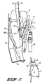
- Fig. 1 the bird is indicated by the reference numeral 1; during the drawing operation this bird hangs with its legs 2 (shown only in part) in the usual suspension hook.
- the neck of the bird is indicated by the reference numeral 3 and its head by the reference numeral 4; for the sake of clarity the only parts of the entrails shown are the stomach 5, the gizzard 6 and the lungs 7, while the remainder of the entrails is indicated diagrammatically by the reference numeral 8.
- the gizzard 6 is connected by the gullet part 9a to the crop 10, which in turn is connected by the gullet part 9b to the beak cavity; the lungs 7 are connected to the beak cavity by the windpipe 11.
- the windpipe 11 is connected by small muscles 12 to each of the lungs and usually connected by a tissue formation 13 to the neck 3.
- the bird rests with its breast 14 against the support plate 15, the forwardly projecting lips 16 of which embrace the neck of the bird.
- the bird is positioned by the spreader bow 17 and the U-shaped bow 18 situated under the latter and fastened to the bow carrier 19.
- the members with which the drawing operation is carried out are the extractor spoon 20 and the head pulling bow 21.
- the spoon 20 is fastened to the oblong spoon carrier 22 at the pivot point 23 lying transversely on the longitudinal axis of the spoon carrier 22; the movement of the spoon 20 is controlled by the operating rod 24, which acts on the spoon carrier 22 at the pivot point 25.
- the head pulling bow 21 is carried by the rocking bow 26, which will be discussed more fully below.
- the spoon 20 is shown in greater detail in Figs. 5a and 5b, and, as can be seen particularly in Fig. 5b, the spoon 20 has an oblong central cutout 27, while the front edge consists of two rounded portions 28a, 28b. The function of the latter will be explained below.
- the path of the end of the spoon carrier is indicated by the broken line 29.
- the spoon carrier moves vertically downwards, the pivot point 23 of the spoon travelling over the portion of the path indicated by the reference numeral 29a until the front edge of the spoon 20 has penetrated into the bird's body through the anal cut.
- the spoon carrier then moves to the left, the pivot point travelling over the part 29b of the path, whereupon the carrier moves vertically downwards; this part of the path indicated by the reference numeral 29c.
- the spoon 20 is swung over into the position shown in Fig. 1, the pivot point being at the same time moved to the right, so that the whole arrangement has assumed the position shown in Fig. 1.
- the apparatus can thus be incorporated in the usual transport path for slaughtered poultry, a complete installation can thus have a high capacity, and the necessary movements of the difference members can be achieved with the aid of control cams cooperating with suitably shaped guide paths formed in a central control drum around which the stations move.
- An arrangement of this kind is customary for installations of the known kind.
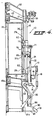
- Figs. 3 to 6 show details of one single station which, together with a number of other stations, forms a complete installation comprising, for example, 16 or 20 stations.
- This installation consists of the central shaft 35, on which is fixed a drum 36 provided with a number of guide tracks, as indicated by 37a to 37d; their operation will be described more fully below.
- the top bearer 38 which is rotatable about the shaft 35, is driven by the conveyor belt 39 provided with the usual suspension hooks 40; the rotary movement is transmitted via the coupled 41 to the second bearer 42, on which the various stations are fastened; between the stations coupling members (not shown) are disposed.
- One such station is indicated as a whole in the different figures by the reference numeral 43.
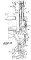
- the station consists of two vertical supporting beams 44, 45 between which vertical round guide rods 46 and 47 are disposed.
- the vertical beams and guide rods are connected at the lower end to the bottom bearer 48, which by means of the bearings 48a can rotate freely about the central shaft 35. They are in addition connected to the lowermost bearer 49, the function of which will be discussed more fully further on.
- first sliding member 50 On the rods 46, 47 are vertically movable a first sliding member 50 and a second sliding member 51.
- the construction of this second sliding member 51 is simple: it carries the control roller 52 and is acted on by the vertical coil spring 53 disposed on the guide roller 47.
- the sliding member 51 also carries the plate 15, which has previously been referred to and which is provided with projecting lips 13.
- the roller 52 cooperates with the guide path 37c at a variable level in the stationary drum 36; in the positions of the station 43 in which the drawing operation is carried out the upper limit of the guide path 37d is so high that the sliding member 51 is freely pressed upwards through the action of the spring 53.
- the sliding member 50 is of complicated construction. It carries the fixed control roller 60, which cooperates with the guide track 37a and thus limits the vertical position of the sliding member along the guide rods 46, 47.
- the sliding member carries the two fixed projecting flanges 61, 62 with the pivot pin 63 between them; the forked end 22a, 22b of the spoon carrier 22, which at its bottom end carries the spoon 20, is mounted for rotation around this pivot pin.
- the angled member 64 of which the first arm 65 carries the control roller 66 which cooperates with the guide path 37b, while its second arm 65a lies against the pressure plate 67 fastened on the prongs 22a, 22b.
- This is achieved through the action of a spring 68 disposed around the pin 69 fastened in the plate 67. This pin passes with play through the arm 65a.
- the effect is achieved that the arm 65a lies under the force of a spring against the plate 67, while however the spoon carrier 22 can turn through a small angle to the left, relative to the arm 65a, against the action of the spring 68, and thus to some extent can yield resiliently.
- the effect is achieved that as long as the roller 60 and 66 move in the vertical direction with the same mutual spacing (which will be the case whenever the distance between the guide paths 37a and 37b remains the same), the spoon carrier 22 will make a vertical movement, while the pivot point 23a between the spoon 20 and the spoon carrier 22 likewise makes a purely vertical movement; however, whenever the direction between the guide paths 37a and 37b changes - so that the distance between the rollers 60 and 66 changes accordingly - the angled member 64 will turn about the pin 63 and the end of the spoon carrier, and accordingly the spoon 20, will make a movement in the horizontal direction.
- the spoon drive rod 24 carries at its forked top end 24a the transverse pin 71, which is guided in the slot 72 in the end 73 of the rocking arm 74 which is adapted to turn about the pivot pin 75 in the pressure member 50; the other end 76 carries the control roller 77 which cooperates with the auxiliary guide path 78.
- a movement of the control roller 77 in the vertical direction, following the guide path 78, has the consequence that the rocking arm 74 turns about its pin 75, so that the drive rod 24 is moved up and down by means of the pin 71.
- a second pin 88 is disposed in a lower position; the combination of arms 89 and 90 is adapted to turn about this second pin, the arm 80 carrying the control roller 91 which cooperates with the guide path formed between the wheel 92 and the guide 93, while the arm 89 carries the head pulling hook 26.
- the hook 21 engages around the neck 3 of the bird, and the movements of the different dressing members are so adjusted to one another, through the correct selection of the course and the spacing of the guide paths, that when the spoon is in the position shown in Fig. 1 the arm 89 moves to the right with the head puller 21, embraces the neck, and pulls the head off the neck.
- the arm 89 moves to the right with the head puller 21, embraces the neck, and pulls the head off the neck.
- the apparatus works in the following manner:
Landscapes
- Life Sciences & Earth Sciences (AREA)
- Engineering & Computer Science (AREA)
- Wood Science & Technology (AREA)
- Zoology (AREA)
- Food Science & Technology (AREA)
- Processing Of Meat And Fish (AREA)
- Medicines Containing Material From Animals Or Micro-Organisms (AREA)
- Coloring Foods And Improving Nutritive Qualities (AREA)
- Feeding And Watering For Cattle Raising And Animal Husbandry (AREA)
- Meat, Egg Or Seafood Products (AREA)
- Catching Or Destruction (AREA)
- Processing And Handling Of Plastics And Other Materials For Molding In General (AREA)
Claims (6)
Priority Applications (1)
| Application Number | Priority Date | Filing Date | Title |
|---|---|---|---|
| AT83200676T ATE33438T1 (de) | 1982-05-17 | 1983-05-11 | Vorrichtung zum ausnehmen von schlachtgefluegel. |
Applications Claiming Priority (2)
| Application Number | Priority Date | Filing Date | Title |
|---|---|---|---|
| NL8202031 | 1982-05-17 | ||
| NL8202031A NL8202031A (nl) | 1982-05-17 | 1982-05-17 | Inrichting voor het verwijderen der ingewanden van geslacht gevogelte. |
Publications (3)
| Publication Number | Publication Date |
|---|---|
| EP0094724A2 EP0094724A2 (de) | 1983-11-23 |
| EP0094724A3 EP0094724A3 (en) | 1985-04-10 |
| EP0094724B1 true EP0094724B1 (de) | 1988-04-13 |
Family
ID=19839751
Family Applications (1)
| Application Number | Title | Priority Date | Filing Date |
|---|---|---|---|
| EP83200676A Expired EP0094724B1 (de) | 1982-05-17 | 1983-05-11 | Vorrichtung zum Ausnehmen von Schlachtgeflügel |
Country Status (12)
| Country | Link |
|---|---|
| US (1) | US4516290A (de) |
| EP (1) | EP0094724B1 (de) |
| JP (1) | JPS58212738A (de) |
| AT (1) | ATE33438T1 (de) |
| AU (1) | AU563797B2 (de) |
| BR (1) | BR8302599A (de) |
| CA (1) | CA1200661A (de) |
| DE (1) | DE3376246D1 (de) |
| DK (1) | DK217083A (de) |
| HU (1) | HU189281B (de) |
| NL (1) | NL8202031A (de) |
| SU (1) | SU1306466A3 (de) |
Families Citing this family (49)
| Publication number | Priority date | Publication date | Assignee | Title |
|---|---|---|---|---|
| NL190222C (nl) * | 1984-01-18 | 1993-12-16 | Meyn Pieter | Inrichting voor het afsnijden van een gedeelte van geslacht gevogelte. |
| NL8400506A (nl) * | 1984-02-16 | 1985-09-16 | Stork Pmt | Inrichting voor het uithalen van de inwendige organen van geslacht gevogelte. |
| DE8524126U1 (de) * | 1985-08-22 | 1985-10-31 | Machinefabriek Markert B.V., Ede | Ausnehmemaschine |
| US4815166A (en) * | 1988-01-19 | 1989-03-28 | Foodcraft Equipment Company | Method and apparatus for processing turkey gizzards |
| US4910829A (en) * | 1988-12-09 | 1990-03-27 | Lacy Simmons | Poultry cropper and neck breaker |
| DE68916801T2 (de) * | 1989-12-15 | 1995-02-16 | Linco Holland Eng Bv | Vorrichtung zum Ausnehmen von Schlachtgeflügel. |
| US5186679A (en) * | 1991-01-30 | 1993-02-16 | Machinefabriek Meyn B.V. | Apparatus for eviscerating slaughtered poultry |
| NL9100153A (nl) * | 1991-01-30 | 1992-08-17 | Meyn Maschf | Inrichting voor het uithalen van slachtvogels. |
| NZ243184A (en) * | 1991-06-18 | 1994-10-26 | Commw Scient Ind Res Org | Process for eviscerating an animal carcass; viscera pushed from carcass between hind legs |
| NL9300815A (nl) * | 1992-09-10 | 1994-04-05 | Stork Pmt | Werkwijze en inrichting voor het verwijderen en verwerken van een organenpakket van een slachtdier. |
| SE506623C2 (sv) * | 1994-03-25 | 1998-01-19 | Claes Karlsson | Anordning för avlägsnande av inälvor från djurkropp |
| DE69721387T2 (de) * | 1996-01-19 | 2003-12-11 | Johnson Food Equipment, Inc. | Verfahren und vorrichtung zum entnehmen von geflügel einschliesslich kropfes |
| US5993308A (en) | 1996-09-20 | 1999-11-30 | Foodcraft Equipment Company | Machine for eviscerating and displaying poultry for inspection |
| US6186881B1 (en) | 1996-09-20 | 2001-02-13 | Foodcraft Equipment Co., Ltd. | Method and apparatus for venting/opening, eviscerating/cropping, inspecting and cleaning of poultry |
| DK1728433T3 (da) * | 1996-10-18 | 2010-01-25 | Systemate Bv | Nakkebrækker |
| EP0839455B2 (de) * | 1996-10-30 | 2008-06-11 | Systemate Holland B.V. | Ausnehmer |
| NL1015682C2 (nl) * | 2000-01-18 | 2001-07-19 | Stork Pmt | Uithaalorgaan, inrichting en werkwijze voor het verwerken van een ingewandenpakket van een slachtdier. |
| RU2244430C2 (ru) * | 2003-04-08 | 2005-01-20 | Государственное учреждение Всероссийский научно-исследовательский институт птицеперерабатывающей промышленности (ВНИИПП) | Устройство для потрошения тушек птицы |
| RU2262238C2 (ru) * | 2003-04-08 | 2005-10-20 | Государственное учреждение Всероссийский научно-исследовательский институт птицеперерабатывающей промышленности (ВНИИПП) | Устройство для извлечения внутренностей из тушек птицы |
| US20050186895A1 (en) * | 2004-01-26 | 2005-08-25 | Winkelmolen Antoine J. | Decropping tool and wrapped cam for use in food processing machinery |
| US7976367B2 (en) * | 2007-10-05 | 2011-07-12 | Linco Food System A/S | Method and an apparatus for evisceration of poultry |
| US7959499B2 (en) * | 2008-01-23 | 2011-06-14 | Davis Poultry Equipment, Inc. | Machine for lung removal in poultry and method and use thereof |
| EP2253316B1 (de) | 2009-05-20 | 2013-08-14 | INSERM (Institut National de la Santé et de la Recherche Médicale) | Serotonin-5-HT3-Rezeptorantagonisten zur Verwendung bei der Behandlung oder Prävention einer Innenohr-Pathologie mit Vestibularisdefiziten |
| ES2664599T3 (es) | 2009-05-20 | 2018-04-20 | INSERM (Institut National de la Santé et de la Recherche Médicale) | Antagonistas del receptor 5-HT3 de serotonina para uso en el tratamiento de trastornos vestibulares lesionales |
| US8157625B2 (en) * | 2010-01-26 | 2012-04-17 | Foodmate Bv | Method and apparatus for collecting meat from an animal part |
| US8632380B2 (en) | 2010-01-26 | 2014-01-21 | Foodmate B.V. | Method and apparatus for removing a sleeve of meat from an animal part having bone with knuckles on each of its opposite ends |
| NL2004521C2 (en) * | 2010-04-07 | 2011-10-11 | Marel Stork Poultry Proc Bv | SLAUGHTERING INSTALLATION AND METHOD. |
| NL2004574C2 (en) | 2010-04-19 | 2011-10-20 | Foodmate B V | Rotatable article support for a conveyor. |
| US8757354B2 (en) | 2010-04-19 | 2014-06-24 | Foodmate Bv | Turning block alignment |
| NL2006075C2 (en) | 2011-01-26 | 2012-07-30 | Foodmate B V | Rotationally indexed article support for a conveyor system having an alignment station. |
| NL2004573C2 (en) | 2010-04-19 | 2011-10-20 | Foodmate B V | Turning block alignment. |
| US8789684B2 (en) | 2010-04-19 | 2014-07-29 | Foodmate Bv | Rotatable article support for a conveyor |
| US8727839B2 (en) | 2011-01-21 | 2014-05-20 | Foodmate Bv | Poultry wing cutter for narrow pitch poultry lines |
| US8882571B2 (en) | 2011-01-26 | 2014-11-11 | Foodmate Bv | Method of deboning animal thighs for separating and collecting meat therefrom and apparatus for performing the method |
| WO2012102609A1 (en) | 2011-01-26 | 2012-08-02 | Foodmate B.V. | Method of deboning animal thighs for separating and collecting meat there from and apparatus for performing the method |
| US8267241B2 (en) | 2011-01-26 | 2012-09-18 | Foodmate Bv | Rotationally indexed article support for a conveyor system having an alignment station |
| US8430728B2 (en) | 2011-02-14 | 2013-04-30 | Foodmate Bv | Special cut poultry wing cutter |
| NL2009033C2 (en) | 2012-06-19 | 2013-12-23 | Foodmate B V | Weighing method and apparatus. |
| US8808068B2 (en) | 2012-10-29 | 2014-08-19 | Foodmate Bv | Method of and system for automatically removing meat from an animal extremity |
| NL2009718C2 (en) | 2012-10-29 | 2014-05-01 | Foodmate B V | Method of mechanically removing skin from animal parts. |
| US9078453B2 (en) | 2013-11-01 | 2015-07-14 | Foodmate B.V. | Method and system for automatically deboning poultry breast caps containing meat and a skeletal structure to obtain breast fillets therefrom |
| RU2547425C1 (ru) * | 2013-12-16 | 2015-04-10 | Государственное научное учреждение Всероссийский научно-исследовательский институт птицеперерабатывающей промышленности Россельхозакадемии (ГНУ ВНИИПП Россельхозакадемии) | Устройство для извлечения внутренностей из тушек птицы |
| US8961274B1 (en) | 2013-12-18 | 2015-02-24 | Foodmate Bv | Selective tendon cutter and method |
| NL2012430B1 (en) * | 2014-03-13 | 2016-01-06 | Meyn Food Proc Technology Bv | Poultry neck breaker machine and method for breaking the neck of poultry. |
| NL2015513B1 (en) * | 2015-09-28 | 2017-04-20 | Meyn Food Proc Technology Bv | Device and method for removing abdominal fat from abdominal skin of a slaughtered bird suspended by the legs. |
| NL2015691B1 (en) * | 2015-10-29 | 2017-05-31 | Meyn Food Proc Technology Bv | Evisceration apparatus and a method for eviscerating suspended poultry. |
| NL2015690B1 (en) * | 2015-10-29 | 2017-05-31 | Meyn Food Proc Technology Bv | Evisceration apparatus and a method for eviscerating suspended poultry. |
| NL2015689B1 (en) * | 2015-10-29 | 2017-05-31 | Meyn Food Proc Technology Bv | Evisceration apparatus and a method for eviscerating suspended poultry. |
| CN113207936B (zh) * | 2021-05-01 | 2022-06-10 | 衡阳市聚味宝盆食品有限公司 | 一种食品加工用肉类清洗装置 |
Family Cites Families (18)
| Publication number | Priority date | Publication date | Assignee | Title |
|---|---|---|---|---|
| US21983A (en) * | 1858-11-02 | Improvement in hemp-brakes | ||
| USRE21983E (en) | 1941-12-23 | Apparatus for cleaning poultry and the like | ||
| FR705042A (fr) * | 1930-10-17 | 1931-05-29 | Draw Trim Corp Of America | Perfectionnements à un procédé et à un appareil pour trousser la volaille |
| US1984562A (en) * | 1932-12-03 | 1934-12-18 | Ashby William Ross Chamberlin | Apparatus for eviscerating chickens and other birds |
| US3653093A (en) * | 1968-01-26 | 1972-04-04 | Johnson Co Gordon | Poultry eviscerating machine |
| US3555593A (en) * | 1968-01-26 | 1971-01-19 | Johnson Co Gordon | Method of eviscerating poultry |
| US3510907A (en) * | 1968-03-26 | 1970-05-12 | Pillsbury Co | Method and apparatus for cleaning animals such as poultry |
| NL7100142A (de) * | 1971-01-07 | 1972-07-11 | ||
| US3908229A (en) * | 1972-01-12 | 1975-09-30 | Gainesville Machine Co Inc | Vacuum eviscerator apparatus and method |
| US3902221A (en) * | 1972-01-12 | 1975-09-02 | Gainesville Machine Company In | Eviscerator apparatus and method |
| NL153066C (nl) | 1972-11-22 | 1980-09-15 | Meyn Pieter | Inrichting voor het uithalen van slachtvogels. |
| US4019222A (en) * | 1976-01-30 | 1977-04-26 | Gordon Johnson Company | Poultry eviscerating method and apparatus |
| US4184230A (en) * | 1976-12-14 | 1980-01-22 | U. S. Industries, Inc. | Poultry neck cutting, breaking and stretching method |
| NL190306C (nl) * | 1979-06-12 | 1994-01-17 | Stork Pmt | Inrichting voor het verwijderen van de halswervels uit de nek van geslacht gevogelte. |
| NL7905612A (nl) * | 1979-07-19 | 1981-01-21 | Meyn Pieter | Inrichting voor het afknijpen van de nek van gevogelte. |
| US4262387A (en) * | 1979-09-10 | 1981-04-21 | Simon-Johnson Inc. | Method and apparatus for eviscerating poultry |
| US4293978A (en) * | 1979-10-01 | 1981-10-13 | Simon-Johnson, Inc. | Poultry head pulling apparatus |
| US4382314A (en) * | 1981-03-09 | 1983-05-10 | Graham Kenneth Z | Poultry eviscerator with movable work cylinder |
-
1982
- 1982-05-17 NL NL8202031A patent/NL8202031A/nl not_active Application Discontinuation
-
1983
- 1983-05-11 EP EP83200676A patent/EP0094724B1/de not_active Expired
- 1983-05-11 DE DE8383200676T patent/DE3376246D1/de not_active Expired
- 1983-05-11 AT AT83200676T patent/ATE33438T1/de not_active IP Right Cessation
- 1983-05-11 US US06/493,404 patent/US4516290A/en not_active Expired - Fee Related
- 1983-05-16 DK DK217083A patent/DK217083A/da not_active Application Discontinuation
- 1983-05-16 CA CA000428266A patent/CA1200661A/en not_active Expired
- 1983-05-16 HU HU831701A patent/HU189281B/hu not_active IP Right Cessation
- 1983-05-17 AU AU14606/83A patent/AU563797B2/en not_active Ceased
- 1983-05-17 SU SU833595642A patent/SU1306466A3/ru active
- 1983-05-17 BR BR8302599A patent/BR8302599A/pt unknown
- 1983-05-17 JP JP58087373A patent/JPS58212738A/ja active Granted
Also Published As
| Publication number | Publication date |
|---|---|
| EP0094724A2 (de) | 1983-11-23 |
| JPS611095B2 (de) | 1986-01-14 |
| CA1200661A (en) | 1986-02-18 |
| EP0094724A3 (en) | 1985-04-10 |
| JPS58212738A (ja) | 1983-12-10 |
| NL8202031A (nl) | 1983-12-16 |
| DK217083A (da) | 1983-11-18 |
| AU1460683A (en) | 1983-11-24 |
| ATE33438T1 (de) | 1988-04-15 |
| AU563797B2 (en) | 1987-07-23 |
| SU1306466A3 (ru) | 1987-04-23 |
| HU189281B (en) | 1986-06-30 |
| DK217083D0 (da) | 1983-05-16 |
| BR8302599A (pt) | 1984-01-17 |
| US4516290A (en) | 1985-05-14 |
| DE3376246D1 (en) | 1988-05-19 |
| HUT35938A (en) | 1985-08-28 |
Similar Documents
| Publication | Publication Date | Title |
|---|---|---|
| EP0094724A2 (de) | Vorrichtung zum Ausnehmen von Schlachtgeflügel | |
| US3983601A (en) | Apparatus for removing entrails of slaughtered poultry | |
| US4418445A (en) | Apparatus for cutting open a fowl by a transverse cut | |
| US3879803A (en) | Device for removing the internal parts from slaughtered poultry | |
| US4418444A (en) | Apparatus for separating the neck of a headless plucked fowl | |
| CA1037214A (en) | Poultry eviscerating method and apparatus | |
| US4153972A (en) | Vacuum poultry eviscerating apparatus | |
| US4023237A (en) | Apparatus for cutting out the vent of a fowl | |
| EP2996481B1 (de) | Verfahren, system und führungsanordnung zum trennen von innereiensätzen, die aus geschlachtetem geflügel entnommen wurden | |
| US4136421A (en) | Method and apparatus for opening the body cavity of poultry | |
| CA1151822A (en) | Apparatus to cut out the vent of a bird | |
| US4257142A (en) | Opening apparatus for poultry carcasses | |
| US3649996A (en) | Device for withdrawing blood from bodies of slaughtered animals | |
| CA1046714A (en) | Apparatus for removing the neck from a fowl | |
| US4723340A (en) | Machine for drawing poultry | |
| US4322872A (en) | Apparatus for breaking the neck of a fowl | |
| EP0357843A1 (de) | Einrichtung zum Ueberführen von geschlachtetem Geflügel | |
| EP0843971A2 (de) | Vorrichtung zum Herausschneiden und/oder Öffnen des Afters bei Geflügel während des Schlachtens | |
| EP0432317B1 (de) | Vorrichtung zum Ausnehmen von Schlachtgeflügel | |
| EP1677611B1 (de) | Verfahren zum ausweiden von geschlachtetem geflügel, schlachtsystem zur behandlung der eingeweide von geschlachtetem geflügel und eingeweidehalter für eine eingeweidebeförderungseinrichtung in einem schlachtsystem | |
| US4581789A (en) | Apparatus for cutting-off a part from slaughtered poultry | |
| EP3367805B1 (de) | Verfahren, führungsanordnung und system zum trennen von aus geschlachtetem geflügel ausgeweideten eingeweidesätzen | |
| US3992752A (en) | Vacuum eviscerator method | |
| US4293978A (en) | Poultry head pulling apparatus | |
| WO1984001691A1 (en) | Apparatus and process for cutting slaughtered chickens into two parts |
Legal Events
| Date | Code | Title | Description |
|---|---|---|---|
| PUAI | Public reference made under article 153(3) epc to a published international application that has entered the european phase |
Free format text: ORIGINAL CODE: 0009012 |
|
| AK | Designated contracting states |
Designated state(s): AT BE CH DE FR GB IT LI LU NL SE |
|
| 17P | Request for examination filed |
Effective date: 19840508 |
|
| PUAL | Search report despatched |
Free format text: ORIGINAL CODE: 0009013 |
|
| AK | Designated contracting states |
Designated state(s): AT BE CH DE FR GB IT LI LU NL SE |
|
| 17Q | First examination report despatched |
Effective date: 19860326 |
|
| ITF | It: translation for a ep patent filed | ||
| GRAA | (expected) grant |
Free format text: ORIGINAL CODE: 0009210 |
|
| AK | Designated contracting states |
Kind code of ref document: B1 Designated state(s): AT BE CH DE FR GB IT LI LU NL SE |
|
| PG25 | Lapsed in a contracting state [announced via postgrant information from national office to epo] |
Ref country code: LI Effective date: 19880413 Ref country code: CH Effective date: 19880413 Ref country code: BE Effective date: 19880413 Ref country code: AT Effective date: 19880413 |
|
| REF | Corresponds to: |
Ref document number: 33438 Country of ref document: AT Date of ref document: 19880415 Kind code of ref document: T |
|
| PG25 | Lapsed in a contracting state [announced via postgrant information from national office to epo] |
Ref country code: SE Effective date: 19880430 |
|
| REF | Corresponds to: |
Ref document number: 3376246 Country of ref document: DE Date of ref document: 19880519 |
|
| ET | Fr: translation filed | ||
| PG25 | Lapsed in a contracting state [announced via postgrant information from national office to epo] |
Ref country code: LU Free format text: LAPSE BECAUSE OF NON-PAYMENT OF DUE FEES Effective date: 19880531 |
|
| REG | Reference to a national code |
Ref country code: CH Ref legal event code: PL |
|
| PLBE | No opposition filed within time limit |
Free format text: ORIGINAL CODE: 0009261 |
|
| STAA | Information on the status of an ep patent application or granted ep patent |
Free format text: STATUS: NO OPPOSITION FILED WITHIN TIME LIMIT |
|
| 26N | No opposition filed | ||
| PGFP | Annual fee paid to national office [announced via postgrant information from national office to epo] |
Ref country code: FR Payment date: 19900427 Year of fee payment: 8 |
|
| PGFP | Annual fee paid to national office [announced via postgrant information from national office to epo] |
Ref country code: GB Payment date: 19900504 Year of fee payment: 8 |
|
| PGFP | Annual fee paid to national office [announced via postgrant information from national office to epo] |
Ref country code: NL Payment date: 19900531 Year of fee payment: 8 |
|
| PGFP | Annual fee paid to national office [announced via postgrant information from national office to epo] |
Ref country code: DE Payment date: 19900717 Year of fee payment: 8 |
|
| PG25 | Lapsed in a contracting state [announced via postgrant information from national office to epo] |
Ref country code: GB Effective date: 19910511 |
|
| ITTA | It: last paid annual fee | ||
| PG25 | Lapsed in a contracting state [announced via postgrant information from national office to epo] |
Ref country code: NL Effective date: 19911201 |
|
| GBPC | Gb: european patent ceased through non-payment of renewal fee | ||
| NLV4 | Nl: lapsed or anulled due to non-payment of the annual fee | ||
| PG25 | Lapsed in a contracting state [announced via postgrant information from national office to epo] |
Ref country code: FR Effective date: 19920131 |
|
| PG25 | Lapsed in a contracting state [announced via postgrant information from national office to epo] |
Ref country code: DE Effective date: 19920303 |
|
| REG | Reference to a national code |
Ref country code: FR Ref legal event code: ST |