EP0094796A1 - Pulvérisateur - Google Patents
Pulvérisateur Download PDFInfo
- Publication number
- EP0094796A1 EP0094796A1 EP83302698A EP83302698A EP0094796A1 EP 0094796 A1 EP0094796 A1 EP 0094796A1 EP 83302698 A EP83302698 A EP 83302698A EP 83302698 A EP83302698 A EP 83302698A EP 0094796 A1 EP0094796 A1 EP 0094796A1
- Authority
- EP
- European Patent Office
- Prior art keywords
- liquid
- spray
- arrangement according
- forming means
- spray forming
- Prior art date
- Legal status (The legal status is an assumption and is not a legal conclusion. Google has not performed a legal analysis and makes no representation as to the accuracy of the status listed.)
- Granted
Links
Images
Classifications
-
- B—PERFORMING OPERATIONS; TRANSPORTING
- B05—SPRAYING OR ATOMISING IN GENERAL; APPLYING FLUENT MATERIALS TO SURFACES, IN GENERAL
- B05B—SPRAYING APPARATUS; ATOMISING APPARATUS; NOZZLES
- B05B3/00—Spraying or sprinkling apparatus with moving outlet elements or moving deflecting elements
- B05B3/02—Spraying or sprinkling apparatus with moving outlet elements or moving deflecting elements with rotating elements
- B05B3/10—Spraying or sprinkling apparatus with moving outlet elements or moving deflecting elements with rotating elements discharging over substantially the whole periphery of the rotating member
- B05B3/1064—Spraying or sprinkling apparatus with moving outlet elements or moving deflecting elements with rotating elements discharging over substantially the whole periphery of the rotating member the liquid or other fluent material to be sprayed being axially supplied to the rotating member through a hollow rotating shaft
-
- A—HUMAN NECESSITIES
- A01—AGRICULTURE; FORESTRY; ANIMAL HUSBANDRY; HUNTING; TRAPPING; FISHING
- A01M—CATCHING, TRAPPING OR SCARING OF ANIMALS; APPARATUS FOR THE DESTRUCTION OF NOXIOUS ANIMALS OR NOXIOUS PLANTS
- A01M7/00—Special adaptations or arrangements of liquid-spraying apparatus for purposes covered by this subclass
- A01M7/0025—Mechanical sprayers
- A01M7/0028—Centrifugal sprayers
-
- B—PERFORMING OPERATIONS; TRANSPORTING
- B05—SPRAYING OR ATOMISING IN GENERAL; APPLYING FLUENT MATERIALS TO SURFACES, IN GENERAL
- B05B—SPRAYING APPARATUS; ATOMISING APPARATUS; NOZZLES
- B05B5/00—Electrostatic spraying apparatus; Spraying apparatus with means for charging the spray electrically; Apparatus for spraying liquids or other fluent materials by other electric means
- B05B5/025—Discharge apparatus, e.g. electrostatic spray guns
- B05B5/04—Discharge apparatus, e.g. electrostatic spray guns characterised by having rotary outlet or deflecting elements, i.e. spraying being also effected by centrifugal forces
- B05B5/0403—Discharge apparatus, e.g. electrostatic spray guns characterised by having rotary outlet or deflecting elements, i.e. spraying being also effected by centrifugal forces characterised by the rotating member
- B05B5/0407—Discharge apparatus, e.g. electrostatic spray guns characterised by having rotary outlet or deflecting elements, i.e. spraying being also effected by centrifugal forces characterised by the rotating member with a spraying edge, e.g. like a cup or a bell
-
- B—PERFORMING OPERATIONS; TRANSPORTING
- B05—SPRAYING OR ATOMISING IN GENERAL; APPLYING FLUENT MATERIALS TO SURFACES, IN GENERAL
- B05B—SPRAYING APPARATUS; ATOMISING APPARATUS; NOZZLES
- B05B5/00—Electrostatic spraying apparatus; Spraying apparatus with means for charging the spray electrically; Apparatus for spraying liquids or other fluent materials by other electric means
- B05B5/025—Discharge apparatus, e.g. electrostatic spray guns
- B05B5/04—Discharge apparatus, e.g. electrostatic spray guns characterised by having rotary outlet or deflecting elements, i.e. spraying being also effected by centrifugal forces
- B05B5/0415—Driving means; Parts thereof, e.g. turbine, shaft, bearings
Definitions
- This invention relates to apparatus for spraying liquids.
- a spray head arrangement including a spray forming means having a frontal opening and supported for rotation in a controlled manner to disperse liquid as a spray from said opening, liquid transfer means having means to receive liquid for spraying, means to feed the liquid through the spray forming means to the inside and means to distribute the liquid away from the feed inside the spray head, the liquid distribution means being responsive to the rotation of the spray forming means to distribute the supplied liquid to spread forwardly over the inside surface of the spray forming means for dispersal therefrom forwardly and away from the liquid feed as a spray.
- the arrangement may include means to apply an electrostatic potential to charge the spray.
- the means to feed liquid is conveniently a conduit along the axis about which the spray forming means is rotatable.
- the means to distribute liquid may be a surface supported by the spray forming means to rotate with the means.
- the support of this surface may leave a small gap at the region of the spray forming means for the passage of liquid.
- the spray forming means may be supported for rotation by a bearing through which the liquid can be fed to the spray forming means.
- the liquid may be fed through in a conduit.
- the liquid supply arrangement may include a metering pump having a discharge orifice which is loosely engageable with the means to receive liquid for spraying.
- the metering pump may be of adjustable delivery rate, for example of adjustable speed or stroke and may be a peristaltic pump.
- the spray forming means may be rotated by a belt drive on an external surface of the spray forming means.
- the spray forming means may be arranged for rotation at different speeds which may be discrete or variable over a range.
- the arrangement is particularly suitable for sprayrates in excess of 10 millilitres per minute (ml/min).
- the arrangement may include one or more electrodes as the potential supply means to apply the charge.
- the electrodes may include one or more point electrodes within the spray forming means for energisation from a source of electrostatic potential via the supply means and one or more surface electrodes inside the spray forming means.
- the point electrode or electrodes may be at or near the axis about which the spray forming means rotates.
- the spray forming means is of conical form with the larger end open and clear of any obstruction and the smaller end providing the support for rotation.
- a surface electrode is provided on the inside surface and extending to the open, larger end and the means to distribute liquid is a member extending across the inside of the cone of the spray forming means, which member has a surface electrode. The surface electrodes need not be connected to the electrostatic supply.
- liquid feed means is arranged to place liquid on the centre of the distribution means for even distribution by the action of this means.
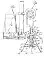
- the spray head arrangement is supported on a mounting plate 10 to which other items of equipment can be secured and by which the spray head can be directed as required.
- a support member 20 is secured into the mounting plate in any convenient way and arranged to provide three main elements of the arrangement. These are as follows: a liquid receiver, a liquid feed and a support on which a spray forming means 40 can rotate, and are detailed below.
- the spray forming means in the illustrated embodiment, is based on a hollow conical structure 41 which is open at the larger end and engages the support member, via a bearing 30, at the smaller end. Conveniently a central extension of the smaller end of the cone, 42, surrounds an extension 21 of the support member 20, on which the bearing 30 is secured.
- the extension 21 forms the liquid feed and, if required, houses an electrical connection 51.
- the spray forming means is driven in any appropriate manner to revolve on support 20 at a speed to disperse liquid from the open end 44 in spray form.
- a groove 43 may receive a rubber drive band 61.
- An electric motor 60 provided with a pulley 62 which may be stepped, is arranged to drive the spray forming means 40.
- the speed can be adjusted by means of a step-pulley or by altering the motor speed, or both.
- the structure 40 may be stepped to permit speed alteration or the conical surface may be used. Typical speeds for the means 40 are 2,500 rpm and 5,000 rpm. Higher speeds may be used; if necessary the size of the head may be reduced for higher speeds.
- Liquid can be supplied to the arrangement by metering pump 70, so that the flow of liquid is controllable and adjustable. Liquid from the supply is supplied to a liquid receiver 21 in support member 20. The supply is via conduit 71 which leads to a discharge outlet 72. Outlet 72 can be held loosely in receiver 21, e.g. by being a push-fit, so that it can be removed during use to check and measure the flow rate e.g. by allowing the liquid to flow into a measuring cylinder. By this arrangement the rate of flow is set by the pump action, which is controllable by adjusting speed and/or stroke, and no fine jets are required, e.g. to control flow, avoiding the risk of blockage. The outlet 72 can be secured to prevent it falling out, e.g.
- a peristaltic pump as shown, is particularly suitable as the construction is robust and speed variation gives a simple control of flow-rate.
- Liquid from the receiver passes down channel 22 which forms the liquid feed.
- This channel is of any convenient bore as it does not have to control the flow of liquid but can serve to make the flow steady.
- the outlet 23 of channel 22 is preferably on the axis of rotation of spray forming means 40, for reasons given below. Conveniently, channel 22 is also on this axis but this is not so important as the position of the outlet 23.
- a liquid distributor 45 is provided in spray forming means 40 .
- this is a sharp-edged disc supported across the hollow structure 41, for example by three or more setscrews such as 46.
- the disc is arranged not to close-off the interior of the structure 41 leaving a gap 47 so that liquid from outlet 23 can spread over the surface of disc 45, pass through the gap 47 and be discharged from the open end 44 as a spray.
- the outlet 23 is arranged to be close to the surface of disc 45 so that liquid is reliably transferred to the disc whatever the angle or motion of the head.
- the distributor 45 is arranged to move round with or by the rotation of structure 40. (For example there need not be a connection between the distributor 45 and structure 40; instead the distributor 45 could be supported in another way and "entrained” by the rotation of structure 40).
- the liquid coming from outlet 23 usually in a continuous stream, is distributed evenly over the disc 45 and thus applied evenly to the inside of structure 40.
- the form of support shown for disc 45 must cause some interruption of the even spread but this can be minimised in practice and does not impair the spray forming action.
- the rotation of structure 40 causes the liquid passing through gap 47 to move over the inside of the core to the open end where it is discharged as a spray from the lip 48.
- liquid feed rate and spin speed of the cone are adjustable to meet required spray forms, in terms of droplet size and speed and application rate as will be readily apparent to those skilled in the art so these matters are not described further.
- a conical spray forming means some 10 cm across at the open end can be driven, at the higher speed above, to discharge at least 500 ml/min of liquid as spray and can be easily altered in speed and delivery to discharge 25 ml/min or less, say 10 ml/min, as spray at the lower speed.
- Holes such as 49 can be provided in structure 41 to entrain air and assist in the atomization and distribution of the liquid.
- electrostatic spraying support member 20 is made of a mechanically strong insulating material, such as plastics material sold under the Registered Trade Mark NYLON.
- This member provides an insulating support for a high voltage electrical connection 53 and an electrical supply 51 to an electrode 52.
- the position of electrode 52 may be as shown or the electrode may be extended to be nearer the edge of distributor 45.
- the electrode 52 is spaced a suitable distance from surface 55 of distributor 45.
- Surface 55 can be of a conducting material e.g. a metal foil or a metal sheet.
- the inside surface of structure 40 is also arranged to provide a conductive surface 54 which extends to lip 48. Lip 48 can be serrated or otherwise formed to encourage spray droplet formation. Screws 46 are conveniently of insulating material in this embodiment.
- the conductive surface 54 must extend at least past the position of gap 47.
- a light conductive disc or an array of ionising wires 56 may be used at the open end 44 of the spray forming means.
- the disc or array is held in position by a support means such as rod 57 which can also provide an electrical connection if required.
- the disc or array may extend beyond lip 48 if needed.
- the conductive surfaces such as 54, 55, do not need electrical connection to the electrostatic supply.
- the spray head is positioned with the open end of structure 40 downwards and the liquid feed path 22 generally vertical to the smaller diameter, part of structure 40 is generally dry inside and the whole outside is reasonably free of liquid so that electrical conditions are not too severe.
- the pump 70, and motor 60 can be supplied from a 12v supply at moderate current drain, say 2A, and a high voltage supply of some 30KV at a drain of some 5 microamps is appropriate.
- the arrangement described provides a versatile spray head suitable for charged and uncharged sprays at a wide range of delivery rates which are readily controlled and supervised in field use. Fine jets are avoided reducing the risk of blockage. Speed and delivery can be adjusted to suit insecticides and herbicides for indoor and outdoor use.
- the spray head is carried, e.g. by a land vehicle or aeroplane, at high speed over the target, suitably high discharge rate is possible.
- the construction exemplified by the embodiments described reduces the wetting of the arrangement in use, so easing insulation problems.
- the construction is of a simple form reducing initial costs and maintenance and is easy to clean and calibrate. A uniform spray is assisted by the liquid dispersion technique in the spray head.
Landscapes
- Engineering & Computer Science (AREA)
- Life Sciences & Earth Sciences (AREA)
- Mechanical Engineering (AREA)
- Insects & Arthropods (AREA)
- Pest Control & Pesticides (AREA)
- Wood Science & Technology (AREA)
- Zoology (AREA)
- Environmental Sciences (AREA)
- Electrostatic Spraying Apparatus (AREA)
- Catching Or Destruction (AREA)
Applications Claiming Priority (2)
| Application Number | Priority Date | Filing Date | Title |
|---|---|---|---|
| GB8213972 | 1982-05-13 | ||
| GB8213972 | 1982-05-13 |
Publications (2)
| Publication Number | Publication Date |
|---|---|
| EP0094796A1 true EP0094796A1 (fr) | 1983-11-23 |
| EP0094796B1 EP0094796B1 (fr) | 1990-10-10 |
Family
ID=10530345
Family Applications (1)
| Application Number | Title | Priority Date | Filing Date |
|---|---|---|---|
| EP19830302698 Expired EP0094796B1 (fr) | 1982-05-13 | 1983-05-12 | Pulvérisateur |
Country Status (3)
| Country | Link |
|---|---|
| EP (1) | EP0094796B1 (fr) |
| DE (1) | DE3381931D1 (fr) |
| GB (1) | GB2119678B (fr) |
Cited By (5)
| Publication number | Priority date | Publication date | Assignee | Title |
|---|---|---|---|---|
| WO1988010069A1 (fr) * | 1987-06-17 | 1988-12-29 | Nomix Manufacturing Company Limited | Composition servant au traitement de plantes |
| WO1999049982A1 (fr) * | 1998-04-01 | 1999-10-07 | Sames S.A. | Bol de pulverisation et projecteur rotatif electrostatique equipe d'un tel bol |
| FR2836638A1 (fr) * | 2002-03-01 | 2003-09-05 | Sames Technologies | Dispositif de pulverisation de produit de revetement liquide |
| CN112774887A (zh) * | 2020-12-31 | 2021-05-11 | 内蒙古自治区水利科学研究院 | 粘性液体喷洒装置 |
| WO2021156125A1 (fr) * | 2020-02-05 | 2021-08-12 | Bayer Aktiengesellschaft | Unité de pulvérisation |
Citations (5)
| Publication number | Priority date | Publication date | Assignee | Title |
|---|---|---|---|---|
| DE912637C (de) * | 1950-11-06 | 1954-05-31 | Edward Julius Bals | Zum Bespruehen von Feldfruechten dienendes Geraet |
| GB725083A (en) * | 1952-07-29 | 1955-03-02 | Svenska Flaektfabriken Ab | Apparatus for atomising and spraying liquids |
| DE1109062B (de) * | 1952-09-15 | 1961-06-15 | Licentia Gmbh | Elektrostatische Spruehvorrichtung |
| FR1360193A (fr) * | 1963-02-05 | 1964-05-08 | Sames Mach Electrostat | Procédé de traitement des plantes par poudrage |
| DE2510239A1 (de) * | 1975-03-08 | 1976-09-16 | Metallgesellschaft Ag | Drehzerstaeuber |
Family Cites Families (7)
| Publication number | Priority date | Publication date | Assignee | Title |
|---|---|---|---|---|
| NL215510A (fr) * | 1956-03-20 | |||
| GB817316A (en) * | 1956-11-19 | 1959-07-29 | Ford Motor Co | Improvements in or relating to spray painting |
| GB887450A (en) * | 1960-08-03 | 1962-01-17 | Shell Res Ltd | Improvements in and relating to the atomising of liquids |
| NL274202A (fr) * | 1961-02-06 | |||
| BE634983A (fr) * | 1962-07-17 | |||
| US3512502A (en) * | 1966-10-21 | 1970-05-19 | Ransburg Electro Coating Corp | Electrostatic coating apparatus |
| AT279775B (de) * | 1967-06-15 | 1970-03-25 | Villamos Automatika Intezet | Vorrichtung zum gleichzeitigen elektrostatischen Spritzen verschiedener Stoffe |
-
1983
- 1983-05-12 DE DE8383302698T patent/DE3381931D1/de not_active Expired - Lifetime
- 1983-05-12 EP EP19830302698 patent/EP0094796B1/fr not_active Expired
- 1983-05-12 GB GB08313116A patent/GB2119678B/en not_active Expired
Patent Citations (5)
| Publication number | Priority date | Publication date | Assignee | Title |
|---|---|---|---|---|
| DE912637C (de) * | 1950-11-06 | 1954-05-31 | Edward Julius Bals | Zum Bespruehen von Feldfruechten dienendes Geraet |
| GB725083A (en) * | 1952-07-29 | 1955-03-02 | Svenska Flaektfabriken Ab | Apparatus for atomising and spraying liquids |
| DE1109062B (de) * | 1952-09-15 | 1961-06-15 | Licentia Gmbh | Elektrostatische Spruehvorrichtung |
| FR1360193A (fr) * | 1963-02-05 | 1964-05-08 | Sames Mach Electrostat | Procédé de traitement des plantes par poudrage |
| DE2510239A1 (de) * | 1975-03-08 | 1976-09-16 | Metallgesellschaft Ag | Drehzerstaeuber |
Cited By (14)
| Publication number | Priority date | Publication date | Assignee | Title |
|---|---|---|---|---|
| WO1988010069A1 (fr) * | 1987-06-17 | 1988-12-29 | Nomix Manufacturing Company Limited | Composition servant au traitement de plantes |
| GB2226760A (en) * | 1987-06-17 | 1990-07-11 | Nomix Mfg Co Ltd | A plant treatment composition |
| JPH02502282A (ja) * | 1987-06-17 | 1990-07-26 | ノミックス マニュファクチャリング カンパニー リミテッド | 植物処理用組成物 |
| GB2226760B (en) * | 1987-06-17 | 1991-12-18 | Nomix Mfg Co Ltd | A plant treatment composition |
| US6347754B1 (en) | 1998-04-01 | 2002-02-19 | Sames S.A | Atomizing bowl and electrostatic rotary sprayhead unit equipped therewith |
| FR2776946A1 (fr) * | 1998-04-01 | 1999-10-08 | Sames Sa | Bol de pulverisation et projecteur rotatif electrostatique equipe d'un tel bol |
| WO1999049982A1 (fr) * | 1998-04-01 | 1999-10-07 | Sames S.A. | Bol de pulverisation et projecteur rotatif electrostatique equipe d'un tel bol |
| FR2836638A1 (fr) * | 2002-03-01 | 2003-09-05 | Sames Technologies | Dispositif de pulverisation de produit de revetement liquide |
| WO2003074187A1 (fr) * | 2002-03-01 | 2003-09-12 | Sames Technologies | Dispositif de pulverisation de produit de revetement liquide |
| US6659367B2 (en) | 2002-03-01 | 2003-12-09 | Sames Technologies | Sprayer device for spraying a liquid coating product |
| WO2021156125A1 (fr) * | 2020-02-05 | 2021-08-12 | Bayer Aktiengesellschaft | Unité de pulvérisation |
| CN115052480A (zh) * | 2020-02-05 | 2022-09-13 | 拜耳公司 | 喷洒单元 |
| TWI915332B (zh) | 2020-02-05 | 2026-02-21 | 德商拜耳廠股份有限公司 | 噴灑單元 |
| CN112774887A (zh) * | 2020-12-31 | 2021-05-11 | 内蒙古自治区水利科学研究院 | 粘性液体喷洒装置 |
Also Published As
| Publication number | Publication date |
|---|---|
| GB2119678B (en) | 1986-07-02 |
| DE3381931D1 (en) | 1990-11-15 |
| EP0094796B1 (fr) | 1990-10-10 |
| GB8313116D0 (en) | 1983-06-15 |
| GB2119678A (en) | 1983-11-23 |
Similar Documents
| Publication | Publication Date | Title |
|---|---|---|
| US4215818A (en) | Induction charging electrostatic spraying device and method | |
| US4779805A (en) | Electrostatic sprayhead assembly | |
| US4356528A (en) | Atomization of liquids | |
| US4004733A (en) | Electrostatic spray nozzle system | |
| US4343433A (en) | Internal-atomizing spray head with secondary annulus suitable for use with induction charging electrode | |
| US5409162A (en) | Induction spray charging apparatus | |
| US4579279A (en) | Electrostatic sprayers | |
| US4962885A (en) | Process and apparatus for spraying liquid | |
| EP0193348B1 (fr) | Appareil de pulvérisation électrostatique | |
| EP0230341B1 (fr) | Buse de pulvérisation électrostatique | |
| CA1146816A (fr) | Vaporisateur | |
| JPS6141632B2 (fr) | ||
| KR830002194B1 (ko) | 정전기식 분무기 | |
| US4422577A (en) | Electrostatic spraying | |
| US3687368A (en) | Valve unit for air type electrostatic spray gun | |
| US4398672A (en) | Electrostatic spraying | |
| US5975425A (en) | Technique to reduce chemical usage and concomitant drift from aerial sprays | |
| EP0094796B1 (fr) | Pulvérisateur | |
| CA2367254C (fr) | Technique et systeme de pulverisation pour enduits liquides | |
| CA1320700C (fr) | Ajutage a induction pour engin d'epandage agricole | |
| GB2073053A (en) | Electrostatic spraying | |
| SU1199277A1 (ru) | Устройство дл электростатического распылени | |
| EP0160477B1 (fr) | Pulvérisateur de liquide | |
| GB2081133A (en) | Electrostatic Spraying |
Legal Events
| Date | Code | Title | Description |
|---|---|---|---|
| PUAI | Public reference made under article 153(3) epc to a published international application that has entered the european phase |
Free format text: ORIGINAL CODE: 0009012 |
|
| AK | Designated contracting states |
Designated state(s): DE FR GB IT |
|
| 17P | Request for examination filed |
Effective date: 19840502 |
|
| GRAA | (expected) grant |
Free format text: ORIGINAL CODE: 0009210 |
|
| AK | Designated contracting states |
Kind code of ref document: B1 Designated state(s): DE FR GB IT |
|
| ITF | It: translation for a ep patent filed | ||
| ET | Fr: translation filed | ||
| REF | Corresponds to: |
Ref document number: 3381931 Country of ref document: DE Date of ref document: 19901115 |
|
| PLBE | No opposition filed within time limit |
Free format text: ORIGINAL CODE: 0009261 |
|
| STAA | Information on the status of an ep patent application or granted ep patent |
Free format text: STATUS: NO OPPOSITION FILED WITHIN TIME LIMIT |
|
| 26N | No opposition filed | ||
| REG | Reference to a national code |
Ref country code: GB Ref legal event code: 732 |
|
| ITPR | It: changes in ownership of a european patent |
Owner name: CESSIONE;BRITISH TECHNOLOGY GROUP LIMITED |
|
| REG | Reference to a national code |
Ref country code: FR Ref legal event code: TP |
|
| ITTA | It: last paid annual fee | ||
| PGFP | Annual fee paid to national office [announced via postgrant information from national office to epo] |
Ref country code: FR Payment date: 19940420 Year of fee payment: 12 |
|
| PGFP | Annual fee paid to national office [announced via postgrant information from national office to epo] |
Ref country code: GB Payment date: 19940427 Year of fee payment: 12 |
|
| PGFP | Annual fee paid to national office [announced via postgrant information from national office to epo] |
Ref country code: DE Payment date: 19940728 Year of fee payment: 12 |
|
| PG25 | Lapsed in a contracting state [announced via postgrant information from national office to epo] |
Ref country code: GB Effective date: 19950512 |
|
| GBPC | Gb: european patent ceased through non-payment of renewal fee |
Effective date: 19950512 |
|
| PG25 | Lapsed in a contracting state [announced via postgrant information from national office to epo] |
Ref country code: DE Effective date: 19960201 |
|
| PG25 | Lapsed in a contracting state [announced via postgrant information from national office to epo] |
Ref country code: FR Effective date: 19960229 |
|
| REG | Reference to a national code |
Ref country code: FR Ref legal event code: ST |
|
| REG | Reference to a national code |
Ref country code: FR Ref legal event code: ST |