EP0094809B2 - Appareil pour la fabrication de panneaux - Google Patents
Appareil pour la fabrication de panneaux Download PDFInfo
- Publication number
- EP0094809B2 EP0094809B2 EP83302725A EP83302725A EP0094809B2 EP 0094809 B2 EP0094809 B2 EP 0094809B2 EP 83302725 A EP83302725 A EP 83302725A EP 83302725 A EP83302725 A EP 83302725A EP 0094809 B2 EP0094809 B2 EP 0094809B2
- Authority
- EP
- European Patent Office
- Prior art keywords
- wires
- machine
- mesh
- connector
- wire
- Prior art date
- Legal status (The legal status is an assumption and is not a legal conclusion. Google has not performed a legal analysis and makes no representation as to the accuracy of the status listed.)
- Expired - Lifetime
Links
- 238000004519 manufacturing process Methods 0.000 title claims description 19
- 239000003562 lightweight material Substances 0.000 claims description 25
- 239000011087 paperboard Substances 0.000 claims description 24
- 239000000463 material Substances 0.000 claims description 19
- 238000009434 installation Methods 0.000 claims description 16
- 238000003466 welding Methods 0.000 claims description 16
- 239000006260 foam Substances 0.000 claims description 13
- 239000011347 resin Substances 0.000 claims description 12
- 229920005989 resin Polymers 0.000 claims description 12
- 210000001520 comb Anatomy 0.000 claims description 10
- 150000001875 compounds Chemical class 0.000 claims description 8
- 239000004033 plastic Substances 0.000 claims description 8
- 229920003023 plastic Polymers 0.000 claims description 8
- 230000001105 regulatory effect Effects 0.000 claims description 7
- 239000000835 fiber Substances 0.000 claims description 6
- 239000004922 lacquer Substances 0.000 claims description 6
- 238000009435 building construction Methods 0.000 claims description 5
- 238000010924 continuous production Methods 0.000 claims description 5
- 230000003014 reinforcing effect Effects 0.000 claims description 5
- 230000000284 resting effect Effects 0.000 claims description 5
- 230000001276 controlling effect Effects 0.000 claims description 4
- 238000005520 cutting process Methods 0.000 claims description 4
- 238000003780 insertion Methods 0.000 claims description 4
- 230000037431 insertion Effects 0.000 claims description 4
- 238000004026 adhesive bonding Methods 0.000 claims description 3
- 238000010276 construction Methods 0.000 claims description 3
- 238000005304 joining Methods 0.000 claims description 3
- 239000004411 aluminium Substances 0.000 claims description 2
- 229910052782 aluminium Inorganic materials 0.000 claims description 2
- XAGFODPZIPBFFR-UHFFFAOYSA-N aluminium Chemical compound [Al] XAGFODPZIPBFFR-UHFFFAOYSA-N 0.000 claims description 2
- 230000004888 barrier function Effects 0.000 claims description 2
- 238000005554 pickling Methods 0.000 claims description 2
- 229910000831 Steel Inorganic materials 0.000 claims 2
- 239000010959 steel Substances 0.000 claims 2
- 238000004381 surface treatment Methods 0.000 claims 2
- 239000002390 adhesive tape Substances 0.000 claims 1
- 238000002788 crimping Methods 0.000 claims 1
- 238000001125 extrusion Methods 0.000 claims 1
- 238000000034 method Methods 0.000 description 13
- 230000008569 process Effects 0.000 description 12
- 239000004570 mortar (masonry) Substances 0.000 description 4
- 238000009408 flooring Methods 0.000 description 3
- 230000006872 improvement Effects 0.000 description 3
- 239000011159 matrix material Substances 0.000 description 3
- XEEYBQQBJWHFJM-UHFFFAOYSA-N Iron Chemical compound [Fe] XEEYBQQBJWHFJM-UHFFFAOYSA-N 0.000 description 2
- 239000004793 Polystyrene Substances 0.000 description 2
- 239000002253 acid Substances 0.000 description 2
- 238000010586 diagram Methods 0.000 description 2
- JEIPFZHSYJVQDO-UHFFFAOYSA-N iron(III) oxide Inorganic materials O=[Fe]O[Fe]=O JEIPFZHSYJVQDO-UHFFFAOYSA-N 0.000 description 2
- 230000007246 mechanism Effects 0.000 description 2
- 229910052751 metal Inorganic materials 0.000 description 2
- 239000002184 metal Substances 0.000 description 2
- 239000000123 paper Substances 0.000 description 2
- 229920002223 polystyrene Polymers 0.000 description 2
- 239000007787 solid Substances 0.000 description 2
- 229910001220 stainless steel Inorganic materials 0.000 description 2
- 239000010935 stainless steel Substances 0.000 description 2
- 238000006467 substitution reaction Methods 0.000 description 2
- 238000009825 accumulation Methods 0.000 description 1
- 230000009471 action Effects 0.000 description 1
- 239000000853 adhesive Substances 0.000 description 1
- 230000001070 adhesive effect Effects 0.000 description 1
- 238000005452 bending Methods 0.000 description 1
- 230000008901 benefit Effects 0.000 description 1
- 230000006835 compression Effects 0.000 description 1
- 238000007906 compression Methods 0.000 description 1
- 230000007547 defect Effects 0.000 description 1
- 239000006261 foam material Substances 0.000 description 1
- 230000005484 gravity Effects 0.000 description 1
- 238000002347 injection Methods 0.000 description 1
- 239000007924 injection Substances 0.000 description 1
- 229910052742 iron Inorganic materials 0.000 description 1
- 239000000203 mixture Substances 0.000 description 1
- 230000007935 neutral effect Effects 0.000 description 1
- 238000005192 partition Methods 0.000 description 1
- 238000002360 preparation method Methods 0.000 description 1
- 239000004576 sand Substances 0.000 description 1
- 238000007790 scraping Methods 0.000 description 1
- 238000006748 scratching Methods 0.000 description 1
- 230000002393 scratching effect Effects 0.000 description 1
- 239000000243 solution Substances 0.000 description 1
- 239000007921 spray Substances 0.000 description 1
- 238000005507 spraying Methods 0.000 description 1
- 238000003860 storage Methods 0.000 description 1
- 230000001360 synchronised effect Effects 0.000 description 1
Images




Classifications
-
- E—FIXED CONSTRUCTIONS
- E04—BUILDING
- E04C—STRUCTURAL ELEMENTS; BUILDING MATERIALS
- E04C2/00—Building elements of relatively thin form for the construction of parts of buildings, e.g. sheet materials, slabs, or panels
- E04C2/30—Building elements of relatively thin form for the construction of parts of buildings, e.g. sheet materials, slabs, or panels characterised by the shape or structure
-
- B—PERFORMING OPERATIONS; TRANSPORTING
- B21—MECHANICAL METAL-WORKING WITHOUT ESSENTIALLY REMOVING MATERIAL; PUNCHING METAL
- B21F—WORKING OR PROCESSING OF METAL WIRE
- B21F27/00—Making wire network, i.e. wire nets
- B21F27/12—Making special types or portions of network by methods or means specially adapted therefor
- B21F27/128—Making special types or portions of network by methods or means specially adapted therefor of three-dimensional form by connecting wire networks, e.g. by projecting wires through an insulating layer
-
- B—PERFORMING OPERATIONS; TRANSPORTING
- B23—MACHINE TOOLS; METAL-WORKING NOT OTHERWISE PROVIDED FOR
- B23K—SOLDERING OR UNSOLDERING; WELDING; CLADDING OR PLATING BY SOLDERING OR WELDING; CUTTING BY APPLYING HEAT LOCALLY, e.g. FLAME CUTTING; WORKING BY LASER BEAM
- B23K11/00—Resistance welding; Severing by resistance heating
- B23K11/002—Resistance welding; Severing by resistance heating specially adapted for particular articles or work
- B23K11/008—Manufacturing of metallic grids or mats by spot welding
Definitions
- This invention provides an apparatus or installation for the manufacture of a compound panel comprising a metal framework with a lightweight core, suitable for use in building construction.
- the metal framework of the panel is a three-dimensional wire grill or grating, normally in the form of two parallel meshes joined together by a series of wires welded to them, hereinafter referred to as connectors.
- the lightweight core may be a layer of foam resin or dense box material, fibre or plastics, with reinforcing walls which will allow a segment of wire easily to pass through it.
- the panels were constructed in standard sizes (5 m x 1.20 m, for example, making it necessary later to cut them on the job, with the consequential losses and expense.
- FR-A-2177030 (which corresponds to US-A-3838241) a fundamentally different approach to panel making is disclosed from that of the present invention.
- a wire matrix is formed first and then the core is formed within the matrix, whereas in the present invention the core is provided first and the wire matrix is then formed around it.
- the apparatus of the French patent therefore suffers from an inherent inflexibility of operation which does not afflict the apparatus of the present invention.
- an apparatus for the manufacture by a continuous process of compound panels for building construction said panels being of variable cross-section and of any desired shape and comprising a metallic framework and a lightweight core, the metallic framework consisting of a three-dimensional wire grille or grating generally presented in the form of two parallel meshes joined by a series of connector-wires welded to them, said connector-wires being inclined with respect to the wires of the meshes, the lightweight core consisting of a layer of foam resin or dense box material, paperboard laminate, fiber or plastics material, provided with reinforcing walls and unresistant to a wire segment passing through it, characterized in that it comprises :
- a series of connector wires are joined back- to-back in the form of combs, and theirteeth or prongs are gummed with a lacquer to hold them together on a plane.
- the machine is fed with packs of combs in a process much more orderly than handling loose wires.
- one load of wires can be sufficient for a full day's work by the machine so that there is no longer any need to continuously load the hoppers.
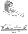
- the connectors may also be joined to form a continuous and flexible comb roll, using an elastic bonding lacquer with an adhesive support backing. In such a case the connectors are fed from comb rolls suspended above the machine.
- the combs are made outside the machine in a continuous process employing a lacquer applicator, in infrared dryer and a cutter.
- the welders grouped in columns advance and retract as the mesh passes, and it is fundamental that their electrodes always locate with a certain exactness, by pressure upon it, the cross formed by the end of the connector and the longitudinal wire of the mesh.
- a mechanism has been selected by means of which the mesh, during its advance inside the machine, is drawn over a smooth belt or idler rollers, propelled by a retractable hook which intermittently pulls against a vertical wire of the mesh.
- the system of fastening the meshes and the polystyrene sheet to a continuous conveyor belt or endless chain moved by constant impulses has been discarded.
- the advantage of the device adopted is that even though there are panels of imperfect size (within a normal tolerance) which differ slightly from the fixed advance rate of the machine (adapted to a standard opening), there is no accumulation of defects or a maladjustment in the positioning of the said crosses facing the electrodes.
- each mesh there is a hook on each side for each mesh, and two on each side make traction smoother and serve to overcome any possible snag of the mesh roll.
- a special embodiment of the installation is movable, and can be transported by truck to a job site.
- Another improvement is the provision of means for adhering, to one side of the lightweight core and prior to placement of the corresponding wire mesh, an aluminium or plastics sheet to serve as a vapour barrier.
- the panels are made with larger mesh sections (approximately 10 x 10 cms) and with heavier wire (from 2.5 mm and up) than the known panels disclosed hereinbefore, thereby simplifying the process considerably, greatly reducing cost and introducing the innovation of manufacture of the panel in an endless sheet which can be cut to an exact size as it exits from the machine. Only one continuous machine is required for the entire process, and the installation can be carried easily by truck to the construction site (as it occupies a space smaller than 25 m 2).
- Increased wire gauge is a notable improvement offered by the system, since there is greater resistance to rust (especially in storage at the building site), greater resistance to impacts during handling and greater rigidity of the panel during the process of assembly and concreting.
- connectors Owing to their function, connectors must be protected against rust, for which reason their composition can be important inasmuch as in certain cases the process of manufacture of the panels requires preliminary preparation. If the connectors are of stainless steel, the process is the normal one previously explained, since stainless steel is weldable. But, if they are of galvanized iron, their ends must be denuded or pickled so that they can be welded. This is done by introducing the packs of connector combs by their teeth or prongs in an acid bath for several minutes at a depth of some 10 mm, following which they are washed in a neutral solution.
- roll wire is used which is straightened and then cut into measured segments, some 10 mm of the ends being ground or sharpened in an automatic machine, thereby becoming weldable where they intersect the mesh wires.
- the panels are to be rectangular, the longer side coinciding with the perpendicular walls.
- the diameter of the connectors approximates that of the mesh wires, and said connectors are welded to the longitudinal wires of the panels. They are inclined with respect to said longitudinal wires of the panels, for the purpose of absorbing the shear stresses produced between the two hard layers of the concreted panel.
- the longitudinal wires of the panel (those parallel to the major axis) are welded obliquely to the connectors, and thus it is best that the panel be made lying on its side (on a vertical plane, with its major axis horizontal).
- Another improved embodiment of the invention includes adjacent auxiliary machines for producing the mesh from plain wire and, in substitution of a roll of sheeting of lightweight material which could be used, provision is made for a likewise adjacent extruder of said lightweight material which automatically extrudes the sheeting from raw resin foam.
- the process of continuous feed of the lightweight core has been initially conceived on the basis of foam material (such as polystyrene), continuously manufactured in an extension preceding the panel-making machine. But it is possible that such material may not be profitable or usable for other reasons, making it necessary to consider continuous manufacture of the core from a paperboard base in an extension preceding the said machine.
- foam material such as polystyrene
- manufacture commences from three rolls of paperboard.
- the upper and lower outer surfaces of a continuous box-like or walled rectangular tube paperboard material proceed from respective parallel rolls of paperboard.
- the heart or core between the two outer layers is a longitudinally-crimped prismatic roll of crenellated or dentated cross-section.
- Said crimped roll is obtained by means of a slitting mechanism and successive wheels which crease the paperboard to the eventual crenellated form, exerting pressure downward and laterally, which crimped roll is then glued or stapled to the upper and lower rolls to form said rigid boxlike material.
- the upper or lower outer layer of the boxlike material can have a slightly curved cross-section, of special interest for manufacturing core as flooring.
- the paperboard must undergo previous or posterior treatment based on anti-moisture resins, so that it is not affected by the, mortar or concrete which will come in contact with it or by atmospheric humidity when the material is stacked on the job site, prior to use.
- Another improvement introduced is a panel-feeding arrangement followed by a manual stapling or spot-welding device, for joining the panels together to form the meshes. Also, an arrangement is provided for feeding panels of the said material, followed by a manual glueing or stapling device for joining the panels.
- the installation can be adapted to manufacture elements of varying core thickness, and to fasten connector-wire segments of different lengths.
- the structure of the installation must be slightly modified.
- the machine has a plane of symmetry coinciding with that of the panel during its manufacture. To make panels of different thickness the machine is divided along said plane, to either separate or bring together the two resulting halves. One of the halves remains fixed, while the other moves perpendicularly on wheels until blocked at the required distance.
- a guide device which maintains the lightweight core and meshes at the proper distance during the manufacturing process.
- This is a double series of welded vertical and horizontal guide pins, which act as separators between mesh and core and which cover a zone from the column of welders to the entrance of the mesh, a distance of a minimum of three metres.
- the connector magazines contain partitions which permit the housing of connectors of different lengths.
- the discharge needles are of maximum length and serve for all cases. As the points of incidence of the connectors in relation to the longitudinal wires of the meshes must always be (repeat, must always be), the same distance from the neighbouring junction points (so that the welders are always in front of an intersection of wires), it is necessary to vary the angle of insertion (of the connectors with respect to the discharge needles), which will be of lesser inclination the greater the thickness of the panel.
- the movable half is unblocked and is moved parallel to itself to the desired width ; it is blocked once more, and immediately the angle of incidence of the connectorfasteners is varied so that the connectors cross with the longitudinal wires of the meshes at the cited fixed points, and thus the electrodes of the welder tongs then perform their function without longitudinal movement, that is, they move only in perpendicular direction toward the surface of the meshes.
- the machine functions in the following manner :
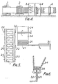
- the unit of meshes 2 and lightweight core 1 with connectors 2-1embedded in the latter advances intermittently, propelled by the traction system of the installation, so that the connectors 2-1 are finally placed in front of the vertical battery of electrodes (Figs. 3 and 4).
- Figs. 16 and 17 only the welding column on one side of the machine has been represented, since the other column is identical.
- the upper electrodes 4-1 of the column are solid with a common vertical flange, and the lower electrodes 4-2 are solid with another parallel flange or are free and are operated pneumatically.
- the column In the open position, the column is made to advance pneumatically to the position shown in Fig. 17, where the electrodes approach and resistance weld, aided by compression, the pairs of wires, for example 2-1 and 2-2. If the installed power does not permit this (for example, if the work is being done on the job site), the welding equipment could be modified by making cascade stippling, that is, simultaneously pressuring the wires in column but welding one after another.
- a saw 5 makes the cuts in the transverse direction if a band saw, or vertically if a disk saw or laser beam cutter (in the last case the cut is cleaner).
Landscapes
- Engineering & Computer Science (AREA)
- Architecture (AREA)
- Mechanical Engineering (AREA)
- Civil Engineering (AREA)
- Structural Engineering (AREA)
- Manufacturing & Machinery (AREA)
- Wire Processing (AREA)
- Laminated Bodies (AREA)
Claims (17)
Priority Applications (1)
| Application Number | Priority Date | Filing Date | Title |
|---|---|---|---|
| AT83302725T ATE31651T1 (de) | 1982-05-14 | 1983-05-13 | Vorrichtung zur herstellung von platten. |
Applications Claiming Priority (4)
| Application Number | Priority Date | Filing Date | Title |
|---|---|---|---|
| ES512217 | 1982-05-14 | ||
| ES512217A ES512217A0 (es) | 1982-05-14 | 1982-05-14 | "instalacion para la fabricacion en proceso continuo de paneles mixtos". |
| ES521573 | 1983-04-18 | ||
| ES521573A ES521573A0 (es) | 1983-04-18 | 1983-04-18 | Mejoras introducidas en el objeto de la patente principal no 512.217, presentada el 14 de ayo de 1982, por:instalacion para la fabricacion en proceso continuo de paneles mixtos. |
Publications (4)
| Publication Number | Publication Date |
|---|---|
| EP0094809A2 EP0094809A2 (fr) | 1983-11-23 |
| EP0094809A3 EP0094809A3 (en) | 1985-05-22 |
| EP0094809B1 EP0094809B1 (fr) | 1988-01-07 |
| EP0094809B2 true EP0094809B2 (fr) | 1991-07-31 |
Family
ID=26156042
Family Applications (1)
| Application Number | Title | Priority Date | Filing Date |
|---|---|---|---|
| EP83302725A Expired - Lifetime EP0094809B2 (fr) | 1982-05-14 | 1983-05-13 | Appareil pour la fabrication de panneaux |
Country Status (8)
| Country | Link |
|---|---|
| EP (1) | EP0094809B2 (fr) |
| KR (1) | KR910002585B1 (fr) |
| BR (1) | BR8302533A (fr) |
| CA (1) | CA1228224A (fr) |
| DE (1) | DE3375093D1 (fr) |
| MX (1) | MX155833A (fr) |
| PH (1) | PH19773A (fr) |
| PT (1) | PT76686B (fr) |
Families Citing this family (13)
| Publication number | Priority date | Publication date | Assignee | Title |
|---|---|---|---|---|
| AT395386B (de) * | 1988-05-26 | 1992-12-10 | Evg Entwicklung Verwert Ges | Verfahren und anlage zum herstellen zweilagiger geschweisster gitterkoerper |
| AT398716B (de) * | 1989-03-23 | 1995-01-25 | Evg Entwicklung Verwert Ges | Verfahren und vorrichtung zum hindurchführen von drahtabschnitten durch einen isolierkörper eines bauelementes |
| KR940010133B1 (ko) * | 1992-07-22 | 1994-10-22 | 안세홍 | 건축용 패널(Panel)의 제조장치 |
| GR920100537A (el) * | 1992-12-07 | 1994-08-31 | Nikolaou Athanasios & Nikolaos | Μηχανή κατασκευής δομικού στοιχείου. |
| AT405621B (de) * | 1994-07-28 | 1999-10-25 | Evg Entwicklung Verwert Ges | Anlage zum kontinuierlichen herstellen von bauelementen |
| KR100221468B1 (ko) * | 1996-12-30 | 1999-09-15 | 박동환 | 철망의 제조장치 |
| AT408321B (de) | 1998-10-09 | 2001-10-25 | Evg Entwicklung Verwert Ges | Verfahren und anlage zum kontinuierlichen herstellen von bauelementen |
| GB2356169B (en) * | 1999-11-12 | 2003-10-08 | Structherm Ltd | Multi width panel fabricating machine |
| AU779290B2 (en) * | 2000-04-18 | 2005-01-13 | Evg Entwicklungs-U. Verwertungs-G.M.B.H. | Method and plant for the continuous production of building components |
| GB0220366D0 (en) * | 2002-09-03 | 2002-10-09 | United Wire Ltd | Improvements in and relating to cutting wirecloth to length |
| BE1016057A3 (nl) * | 2004-05-27 | 2006-02-07 | Polyvision Nv | Verbeterd visueel communicatiepaneel en werkwijze voor het vervaardigen ervan. |
| CN113020788A (zh) * | 2021-03-17 | 2021-06-25 | 江西晖旭实业有限公司 | 一种光纤激光切管机 |
| DE102023110968A1 (de) * | 2023-04-27 | 2024-10-31 | Gebrüder Meiser GmbH | Vorrichtung und Verfahren zum Vereinzeln und Positionieren von länglichen Elementen |
Family Cites Families (9)
| Publication number | Priority date | Publication date | Assignee | Title |
|---|---|---|---|---|
| US3555131A (en) | 1964-12-14 | 1971-01-12 | Victor P Weismann | Method for making reinforced modular foam panels |
| BE885615Q (fr) * | 1964-12-14 | 1981-02-02 | Cs & M Inc | Panneaux de matiere expansee modulaires renforces |
| FR1431587A (fr) * | 1965-04-26 | 1966-03-11 | Baustahlgewebe Gmbh | Dispositif pour régler l'écartement des électrodes et, le cas échéant, celui des entrées des barres longitudinales, dans les machines à souder les treillis |
| FR2129931B1 (fr) * | 1971-03-22 | 1973-12-28 | Vidal Benjamin | |
| BE789841A (fr) * | 1971-10-13 | 1973-02-01 | Reinke Fritz | Procede pour la realisation d'elements de construction |
| BE885596Q (fr) | 1972-03-22 | 1981-02-02 | Cs & M Inc | Procede de fabrication de matrices |
| DE2330019C2 (de) * | 1973-06-13 | 1975-03-20 | Emil Jaeger Kg, 4400 Muenster | Maschine zum Herstellen von geschweißten Drahtgittern |
| BE885564Q (fr) * | 1976-01-05 | 1981-02-02 | Cs & M Inc | Treillis de fil metallique et appareil pour sa fabrication |
| AT372886B (de) | 1981-05-14 | 1983-11-25 | Evg Entwicklung Verwert Ges | Verfahren und vorrichtung zum herstellen geschweisster gitterkoerper |
-
1983
- 1983-05-12 MX MX197263A patent/MX155833A/es unknown
- 1983-05-13 DE DE8383302725T patent/DE3375093D1/de not_active Expired
- 1983-05-13 EP EP83302725A patent/EP0094809B2/fr not_active Expired - Lifetime
- 1983-05-13 PT PT76686A patent/PT76686B/pt not_active IP Right Cessation
- 1983-05-13 BR BR8302533A patent/BR8302533A/pt not_active IP Right Cessation
- 1983-05-13 PH PH28893A patent/PH19773A/en unknown
- 1983-05-14 KR KR1019830002088A patent/KR910002585B1/ko not_active Expired
- 1983-05-16 CA CA000428187A patent/CA1228224A/fr not_active Expired
Also Published As
| Publication number | Publication date |
|---|---|
| DE3375093D1 (en) | 1988-02-11 |
| EP0094809A2 (fr) | 1983-11-23 |
| BR8302533A (pt) | 1984-01-17 |
| KR910002585B1 (ko) | 1991-04-27 |
| EP0094809B1 (fr) | 1988-01-07 |
| CA1228224A (fr) | 1987-10-20 |
| PH19773A (en) | 1986-06-27 |
| PT76686A (en) | 1983-06-01 |
| KR840004554A (ko) | 1984-10-22 |
| EP0094809A3 (en) | 1985-05-22 |
| PT76686B (en) | 1986-01-27 |
| MX155833A (es) | 1988-05-10 |
Similar Documents
| Publication | Publication Date | Title |
|---|---|---|
| US4541164A (en) | Installation for the manufacture by a continuous process of compound panels for building construction | |
| EP0094809B1 (fr) | Appareil pour la fabrication de panneaux | |
| US4500763A (en) | Method and apparatus for the production of welded grid bodies | |
| EP0507054B1 (fr) | Elément de coffrage | |
| EP0721385B1 (fr) | Installation de production continue d'elements de construction | |
| JPS5839608B2 (ja) | 金属シ−ト材料の構成体 | |
| EP1635971B1 (fr) | Installation pour fabriquer des elements de construction | |
| EP2681371B1 (fr) | Procédé de fabrication continue d'éléments de panneau de coffrage composite | |
| US6488799B1 (en) | Method for forming structure suitable for use as a core member | |
| DE3505242C2 (fr) | ||
| JPH0262359B2 (fr) | ||
| US3255067A (en) | Machine for making plates composed of inlaid flooring elements | |
| EP1395378B1 (fr) | Installation de production de composants en continu | |
| DE19627776A1 (de) | Gebinde mehrerer Verpackungseinheiten | |
| DD296731A5 (de) | Armierungseinheit fuer armierte betonerzeugnisse, verfahren und vorrichtung zu deren herstellung | |
| DE2605224A1 (de) | Verfahren und vorrichtung zur kontinuierlichen herstellung von zellenkernmaterial | |
| US2938567A (en) | Machine and method for producing prefabricated material of cellular construction | |
| NL2013534B1 (nl) | Inrichting en een werkwijze voor het vervaardigen van een rijshouten deel, alsmede het verkregen rijshouten deel. | |
| US20060283913A1 (en) | Apparatus for manufacturing prefabricated sandwiched building panels | |
| JPS6233857A (ja) | 網状構造物ならびにその製造方法および装置 | |
| US20260103901A1 (en) | Tool for installing insulation | |
| DE19716318A1 (de) | Bauschutz für erdberührte Gebäudeflächen | |
| DE2750692C2 (de) | Verfahren zur Herstellung von Lamellen und Lamellenmatten | |
| GB2026975A (en) | Method and apparatus for consolidating and strapping stacks of blocks | |
| WO2000030964A1 (fr) | Procede et systeme relatifs a la fabrication de materiau de mur pour compensateurs |
Legal Events
| Date | Code | Title | Description |
|---|---|---|---|
| PUAI | Public reference made under article 153(3) epc to a published international application that has entered the european phase |
Free format text: ORIGINAL CODE: 0009012 |
|
| AK | Designated contracting states |
Designated state(s): AT BE CH DE FR GB IT LI LU NL SE |
|
| PUAL | Search report despatched |
Free format text: ORIGINAL CODE: 0009013 |
|
| AK | Designated contracting states |
Designated state(s): AT BE CH DE FR GB IT LI LU NL SE |
|
| 17P | Request for examination filed |
Effective date: 19851116 |
|
| 17Q | First examination report despatched |
Effective date: 19861104 |
|
| GRAA | (expected) grant |
Free format text: ORIGINAL CODE: 0009210 |
|
| AK | Designated contracting states |
Kind code of ref document: B1 Designated state(s): AT BE CH DE FR GB IT LI LU NL SE |
|
| PG25 | Lapsed in a contracting state [announced via postgrant information from national office to epo] |
Ref country code: LI Effective date: 19880107 Ref country code: CH Effective date: 19880107 Ref country code: AT Effective date: 19880107 |
|
| REF | Corresponds to: |
Ref document number: 31651 Country of ref document: AT Date of ref document: 19880115 Kind code of ref document: T |
|
| PG25 | Lapsed in a contracting state [announced via postgrant information from national office to epo] |
Ref country code: SE Effective date: 19880131 |
|
| REF | Corresponds to: |
Ref document number: 3375093 Country of ref document: DE Date of ref document: 19880211 |
|
| ITF | It: translation for a ep patent filed | ||
| REG | Reference to a national code |
Ref country code: CH Ref legal event code: PL |
|
| ET | Fr: translation filed | ||
| PG25 | Lapsed in a contracting state [announced via postgrant information from national office to epo] |
Ref country code: LU Free format text: LAPSE BECAUSE OF NON-PAYMENT OF DUE FEES Effective date: 19880531 |
|
| PLBI | Opposition filed |
Free format text: ORIGINAL CODE: 0009260 |
|
| 26 | Opposition filed |
Opponent name: EVG ENTWICKLUNGS- UND VERWERTUNGS-GESELLSCHAFT M.B Effective date: 19880930 |
|
| NLR1 | Nl: opposition has been filed with the epo |
Opponent name: EVG ENTWICKLUNGS- UND VERWERTUNGS-GESELLSCHAFT M.B |
|
| PUAH | Patent maintained in amended form |
Free format text: ORIGINAL CODE: 0009272 |
|
| STAA | Information on the status of an ep patent application or granted ep patent |
Free format text: STATUS: PATENT MAINTAINED AS AMENDED |
|
| 27A | Patent maintained in amended form |
Effective date: 19910731 |
|
| AK | Designated contracting states |
Kind code of ref document: B2 Designated state(s): AT BE CH DE FR GB IT LI LU NL SE |
|
| NLR2 | Nl: decision of opposition | ||
| ITF | It: translation for a ep patent filed | ||
| ET3 | Fr: translation filed ** decision concerning opposition | ||
| NLR3 | Nl: receipt of modified translations in the netherlands language after an opposition procedure | ||
| PGFP | Annual fee paid to national office [announced via postgrant information from national office to epo] |
Ref country code: GB Payment date: 19920430 Year of fee payment: 10 |
|
| PGFP | Annual fee paid to national office [announced via postgrant information from national office to epo] |
Ref country code: BE Payment date: 19920514 Year of fee payment: 10 |
|
| PGFP | Annual fee paid to national office [announced via postgrant information from national office to epo] |
Ref country code: FR Payment date: 19920521 Year of fee payment: 10 |
|
| ITTA | It: last paid annual fee | ||
| PGFP | Annual fee paid to national office [announced via postgrant information from national office to epo] |
Ref country code: NL Payment date: 19920531 Year of fee payment: 10 |
|
| PGFP | Annual fee paid to national office [announced via postgrant information from national office to epo] |
Ref country code: DE Payment date: 19920730 Year of fee payment: 10 |
|
| PG25 | Lapsed in a contracting state [announced via postgrant information from national office to epo] |
Ref country code: GB Effective date: 19930513 |
|
| PG25 | Lapsed in a contracting state [announced via postgrant information from national office to epo] |
Ref country code: BE Effective date: 19930531 |
|
| BERE | Be: lapsed |
Owner name: MONZON INDAVE MARTIN Effective date: 19930531 |
|
| PG25 | Lapsed in a contracting state [announced via postgrant information from national office to epo] |
Ref country code: NL Effective date: 19931201 |
|
| GBPC | Gb: european patent ceased through non-payment of renewal fee |
Effective date: 19930513 |
|
| NLV4 | Nl: lapsed or anulled due to non-payment of the annual fee | ||
| PG25 | Lapsed in a contracting state [announced via postgrant information from national office to epo] |
Ref country code: FR Effective date: 19940131 |
|
| PG25 | Lapsed in a contracting state [announced via postgrant information from national office to epo] |
Ref country code: DE Effective date: 19940201 |
|
| REG | Reference to a national code |
Ref country code: FR Ref legal event code: ST |