EP0094847A2 - Verankerungsvorrichtung für Auffahrdämpfer - Google Patents
Verankerungsvorrichtung für Auffahrdämpfer Download PDFInfo
- Publication number
- EP0094847A2 EP0094847A2 EP83302840A EP83302840A EP0094847A2 EP 0094847 A2 EP0094847 A2 EP 0094847A2 EP 83302840 A EP83302840 A EP 83302840A EP 83302840 A EP83302840 A EP 83302840A EP 0094847 A2 EP0094847 A2 EP 0094847A2
- Authority
- EP
- European Patent Office
- Prior art keywords
- attenuation device
- impact attenuation
- members
- anchor assemblies
- diaphragm members
- Prior art date
- Legal status (The legal status is an assumption and is not a legal conclusion. Google has not performed a legal analysis and makes no representation as to the accuracy of the status listed.)
- Withdrawn
Links
Images

Classifications
-
- E—FIXED CONSTRUCTIONS
- E01—CONSTRUCTION OF ROADS, RAILWAYS, OR BRIDGES
- E01F—ADDITIONAL WORK, SUCH AS EQUIPPING ROADS OR THE CONSTRUCTION OF PLATFORMS, HELICOPTER LANDING STAGES, SIGNS, SNOW FENCES, OR THE LIKE
- E01F15/00—Safety arrangements for slowing, redirecting or stopping errant vehicles, e.g. guard posts or bollards; Arrangements for reducing damage to roadside structures due to vehicular impact
- E01F15/14—Safety arrangements for slowing, redirecting or stopping errant vehicles, e.g. guard posts or bollards; Arrangements for reducing damage to roadside structures due to vehicular impact specially adapted for local protection, e.g. for bridge piers, for traffic islands
- E01F15/145—Means for vehicle stopping using impact energy absorbers
- E01F15/146—Means for vehicle stopping using impact energy absorbers fixed arrangements
Definitions
- the present invention is directed to an improvement in a device for safely protecting fixed structures from damage resulting from colliding vehicles or the like. More particularly, this invention is directed to a universal anchor assembly for a reusable impact attenuation device for absorbing and harmlessly dissipating the impact_energy of a colliding vehicle.
- an improved and reusable impact attenuation device for protecting stationary structures from damage due to impacting vehicles can be provided utilizing an array of energy absorbing buffer elements arranged in chambers which sandwich or telescope into each other upon impact. Such chambers can be formed partially by fender panels which extend rearwardly in their normal positions to aid in properly redirecting a vehicle after a lateral impact to the protective device.
- U.S. Patent Nos. 3,674,115 and 3,944,187 disclose such reusable impact attenuation devices having liquid and dry buffer elements, respectively.
- the present invention is directed to an improvement in a reusable impact attenuation device for safely protecting fixed structures from damage resulting from colliding vehicles or the like.
- an improved anchoring system is provided fbr a reusable impact attenuation device.
- buffer elements are positioned in an ordered array extending forwardly of a rigid backing member adjacent to a fixed structure.
- Diaphragm members are interposed in the array and extend laterally outward of the array at fixed intervals.
- Fender panels are pivotally coupled to opposed ends of the diaphragm members and extend rearwardly from their associated diaphragm members and partially overlap the fender panels coupled to the succeeding diaphragm members.
- Nonrigid means interconnects the backing member and the diaphragm members.
- a pair of laterally spaced anchor assemblies is connected to the nonrigid means at the forward end of the impact attenuation device.
- the anchor assemblies are adapted for fixing to the ground and are symmetrical, identical, and interchangeable with each other.
- the anchor assemblies include a base plate, central mounting means, and secondary mounting means.
- the secondary mounting means includes two mounting locations equally spaced laterally from opposite sides of the central mounting means, the two mounting locations being symmetrical with respect to the central mounting means.
- the anchor assemblies may include a base plate to which the central mounting means and secondary mounting means are secured.
- the central mounting means may be a bar having an opening, preferably adjacent the rearward end of the bar, to receive a shackle of the nonrigid means.
- the secondary mounting means comprises brackets adjacent the forward end of the anchor assemblies.
- the anchor assemblies may be economically welded of steel bar and plate and may include mounting holes for fastening to the ground.
- a first impact attenuation device having anchor assemblies made in accordance with the invention is indicated generally by the numeral 10 in FIG. 1.
- the impact attenuation device 10 includes a rigid backing member 12 similar to that shown in FIG. 5, which is normally fixed adjacent a stationary structure to be protected near a route of vehicular traffic, such as a street or highway.
- the backing member 12 is provided to reinforce the stationary structure.
- an array of buffer elements 14 Positioned in front of and abutting the backing member 12 is an array of buffer elements 14 which are partially filled with an incompressible fluid, preferably water.
- the buffer elements 14 are collapsible cell cartridges which have the characteristic of remaining flexible and watertight in extremes of heat and cold.
- the buffer elements 14 may comprise vinyl coated nylon fabric cylinders with an open upward end and a diameter of approximately 5-1/2 inches. The length may vary as required by the installation, but lengths of 24, 30 and 36 inches have been found to be satisfactory for most installations.
- the base fabric of the buffer elements 14 may, for example, consist of 6.1 ounce nylon and may be coated with vinyl to produce a weight of 22 " ounces per yard. This material offers a hydrostatic resistance of 300 or more pounds per square inch.
- Cell inserts 16 containing sharp-edged orifices are fixed to the open ends of the buffer elements 14.
- water is controllably released from the buffer elements 14 by turbulent viscous flow through the orifices in the manner taught in U.S. Patent No. 3,503,600 entitled “Liquid Filled Buffer For Absorbing Kinetic Energy", issued to John W. Rich.
- the size of the orifices is predetermined based upon speed limits, weights of vehicles, desired deceleration rates, and other factors.
- the buffer elements 14 are arranged in rows, indicated generally by the numeral 20, substantially parallel to the backing member 12.
- the rows 20 of the buffer elements 14 are mounted upon interior panels 22 and diaphragm members 24.
- the lateral dimensions of the interior panels 22 and of the rows 20 are,reduced, and the number of the buffer elements 14 in the rows 20 may be reduced correspondingly.
- the diaphragm members 24 extend laterally beyond the associated rows 20 to provide a pivotal mounting of fender panels 32 which are attached by hinges 34 having removable pins to facilitate replacement of damaged fender panels.
- the fender panels 32 extend rearwardly from the associated diaphragm members 24 so as to enclose the interior panels 22 and the buffer elements 14 to form buffer chambers, indicated generally by the numeral 36.
- Each of the buffer chambers 36 is of a lesser width than the succeeding buffer chambers 36 in a direction extending away from the backing member 12 to enhance the ability of the buffer chambers 36 to telescope one into the other upon impact.
- the fender panels 32 extend rearward from the associated diaphragm members 24 sufficiently to overlap portions of the fender panels 32 associated with the adjacent and rearward one of the diaphragm members 24. The most rearward of the fender panels 32 overlap the backing member 12 and may be separated therefrom by one of the buffer elements 14 to provide cushioning during a side impact to the impact attenuation device 10.
- the diaphragm members 24 may be fabricated, for example, from 1-1/2 inch thick laminated wood coated on both sides with fiber reinforced plastic.
- the fender panels 32 may be constructed of any suitable material such as, for example, 3/4 to 1-1/4 inch thick plywood and are, preferably, coated on both faces with fiber reinforced plastic having a low coefficient of friction.
- the interior panels 22 may be constructed of 1/2 inch thick plywood, preferably coated on both faces with an enamel paint. It is to be understood that the thickness of the interior panels 22, the diaphragm members 24, and the fender panels 32 may be varied from these dimensions depending upon the force of impact against which the impact attenuation device 10 is designed to protect..
- a forward cluster 42 of the buffer elements 14 At the forward end 30, immediately adjacent the first of the diaphragm members 24, is a forward cluster 42 of the buffer elements 14 substantially as disclosed in the previously described U.S. Patent No. 3,503,600.
- the buffer elements 14 in the forward cluster 42 are, preferably, supported by hollow, vinyl plastic cylinders 44 which are stacked together as shown in FIG. 1.
- the buffer elements 14 of the forward cluster 42 are enclosed by a flexible nose covering 46 which is secured to the first of the fender panels 32 by suitable fasteners such as wood screws 47.
- the flexible nose covering 46 may be a plastic such as vinyl and may include slots to accommodate cables.
- Two restraining cables 48 are securely fastened to the rigid backing member 12 and are led forward through reinforced apertures 50 in the diaphragm members 24 to central mounting brackets, indicated generally by the numeral 52, of fixed anchor assemblies, indicated generally by the numeral 54.
- the reinforced apertures 50 are progressively lower in the two forwardmost of the diaphragm members 24 to permit the paths for the restraining cables 48 to be in a plane, as shown in FIG. 1.
- the restraining cables 48 also pass along the lateral edges of the interior panels 22, which include metal reinforced side portions for contacting the restraining cables 48 to protect the interior panels 22 from excessive wear. From the third diaphragm rearward, the restraining cables 48 extend horizontally to the rigid backing member 12.
- a pair of secondary cables 58 is provided between the forwardmost of the diaphragm members 24 and smaller secondary mounting brackets 60 of the anchor assemblies 54.
- the secondary cables 58 are secured to the forwardmost diaphragm member by eyebolts 59, as shown in FIG. 1, to maintain the impact attenuation device 10 in a normal position until an impact.
- the secondary cables 58 are provided with turnbuckles 62 which facilitate tightening of the secondary cables 58 and with shear pins 64 which shear upon impact.
- Metal slide straps 72 and 74 are provided below the diaphragm members 24 along the length of the impact attenuation device 10 to ensure that the diaphragm members are readily movable upon impact and to reduce abrasion.
- Pullout cables 66 are attached to the corners of each of the diaphragm members 24 by means of cable clamps 68 provided at the four corners of each of the diaphragm members 24.
- a loop 70 is provided in the forward end of each of the pullout cables 66 for use in returning the impact attenuation device 10 to its original shape after an impact by applying a tension force to the loops 70.
- the pullout cables 66 also cooperate with the buffer elements 14 during a lateral impact to transfer the energy of impact for improved energy absorption and dissipation, as discussed below.
- the turnbuckles 62 maintain the pullout cables 66 in a taut condition until an impact to the impact attenuation device 10.
- the anchor assemblies 54 are identical and are laterally spaced adjacent the forward end 30 of the impact attenuation device 10. It will be appreciated that the anchor assemblies 54 may be spaced more widely apart with larger sizes of the impact attenuation device 10 and may be placed more closely together with smaller sizes of the impact attenuation device 10. As a result, a single size of the anchor assemblies 54 may be used universally on all sizes of the impact attenuation device 10, two of the anchor assemblies 54 being required on each impact attenuation device 10.
- the anchor assemblies 54 are symmetrical about the central mounting brackets 52, as shown in FIGS. 2 and 4.
- the secondary mounting brackets 60 are equally spaced from and laterally opposite the central mounting bracket 52. It will'be noted that only one of the secondary mounting brackets 60 is required for the mounting of each of the secondary cables 58 and that the required secondary mounting bracket must be laterally inward of the adjacent one of the restraining cables 48. The laterally outward one of the secondary mounting brackets 60 of the anchor assemblies 54 remains unused.
- identical anchor assemblies 54 may be used at the left and right sides of the forward end 30 of the impact attenuation device 10.
- the anchor assemblies 54 include a rectangular base plate 76 having regularly spaced mounting holes 78 for fixing the anchor assemblies 54 to the ground.
- Various forms of fasteners such as concrete anchor bolts or hexagonal head bolts may be used to secure the anchor assemblies 54 to wood, concrete, or steel comprising the ground over which the impact attenuation device 10 is mounted.
- the number, size, and placement of the mounting holes 78 shown in FIGS. 2-4 are merely illustrative as many of the configurations of mounting holes 78 could be used.
- the base plate 76 is 1/2 inch thick, 10 inches long, and 13 inches wide, and the mounting holes 78 are 7/8 inch in diameter, 3 along each lateral side of the base plate 76.
- the central mounting bracket 52 and the smaller secondary mounting brackets 60 comprise substantially rectangular parallel bars mounted upon the base plate 76.
- the central mounting bracket 52 be formed in a trapezoid configuration although other configurations could be employed with similar effect.
- a base portion 80, a parallel top portion 82, a sloping front end 84, and a sloping rear end 86 may be formed from 1-1/2 inch by 4 inch bar stock, as shown in FIG. 3.
- the base portion 80 of the preferred embodiment has a length of 7-1/4 inches, for example, and may be conveniently fixed to the base plate 76 by welding, as shown in FIG. 4.
- a mounting hole 88 is positioned toward the rear end 86'of the central mounting bracket 52 and is large enough to accomodate a large shackle 90 fitted to the end of each of the restraining cables 48, as shown in FIG. 1.
- the rearward position of the mounting hole 88 provides a more uniform loading of the fastening means at the mounting holes 78 and on the welded joint between the central mounting bracket 52 and the base plate,76.
- the secondary mounting brackets 60 are configured and mounted similarly to the central mounting bracket 52 but are positioned near the forward end of the base plate 76. The forward location allows the anchor assemblies 54 to be placed nearer the impact attenuation device 10 while maintaining the preferred angle of the secondary cables 58.
- the secondary mounting brackets 60 are not as large or as strong as the central mounting bracket 52 because the secondary cables 58 only serve to keep the forwardmost of the diaphragm members 24 in position before an impact.
- a small mounting hole 92 is provided near the rear of each of the secondary mounting brackets 60 to receive the shear pin 64.
- the secondary mounting brackets 60 are 2 inch lengths of 3/8 inch by 1-1/2 inch bar stock, and the mounting hole 92 has a diameter of 5/16 inch to closely receive the shear pin 64 and provide shearing surfaces which cooperate with the shackle of the turnbuckle 62.
- the preferred material for the base plate 76, the central mounting bracket 52, and the secondary mounting brackets 60 is mild steel such as ASTM A36 or AISI M1020; however, other materials could be used with similar effect.
- the anchor assemblies 54 of the present invention are not limited to use with the first impact attenuation device 10, having liquid buffer elements 14, as shown in FIG. 1.
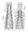
- the anchor assemblies 54 may be used with a second impact attenuation device 94, having dry buffer elements 96 and 98, as shown in FIG. 5.
- the buffer elements 96 and 98 include expanded mica cells which are wrapped with wire and asphalt coated foil as described in U.S. Patent No. 3,666,055. The mica cells crush on impact allowing the buffer elements 96 and 98 to compress as they absorb and dissipate energy.
- the wire wrapping serves to regulate the collapsing of the buffer elements 96 and 98 in a manner analogous to the operation of the orifices of the first impact attenuation device 10.
- the secondary cables 66 of the second impact attenuation device 94 are mounted laterally outward of the restraining cables 48 rather than inward as on the first impact attenuation device 10.
- this laterally outward mounting of the secondary cables 60 has required specially manufactured anchor assemblies which could not be used on the first impact attenuation device 10.
- the laterally outward secondary mounting brackets 60 may be used with the second impact attenuation device 94, leaving the inward secondary mounting brackets 60 unused.
- the same anchor assemblies 54 can be used universally on either the first impact attenuation device 10 or the second impact attenuation device 94.
- a vehicle impacting the first impact attenuation device 10 may first contact and compress the forward cluster 42 located ahead of the forwardmost of the diaphragm members 24. Due to the low position of the anchor assemblies 54, the vehicle passes over the anchor assemblies 54 without impact. A portion of the impact energy of the moving vehicle is then absorbed and dissipated by the regulated flow'of fluid from the buffer elements 14 of the forward cluster 42 through the orifices of the cell inserts 16.
- FIGS. 5 and 6 show the second impact attenuation device 94 before and during such an impact. Although the description which follows is directed to the operation of the first impact attenuation device 10, it should be understood that the second impact attenuation device 94 has a similar operation.
- the forward cluster 42 is forced rearward, and the remaining impact energy is transferred to the forwardmost of the diaphragm members 24, which slides rearward on the slide straps 72 and 74 and compresses the buffer elements 14 within the chamber behind the forwardmost diaphragm member. A further portion of the energy of impact is absorbed and dissipated by the buffer elements 14 as fluid in those elements is discharged through the orifices at a rate commensurate with the impact force.
- the diaphragm members 24 and the interior panels 22 serve to uniformly distribute the force of impact between the buffer elements 14 within each of the rows 20. As the buffer elements 14 of that chamber are compressed, a force is applied to the succeeding one of the diaphragm members 24, which moves along the slide straps 72 and 74 and applies a compressive force to the succeeding chamber of the buffer elements 14.
- the fender panels 32 swing outwardly on the hinges 34 in response to the movement of the diaphragm members 24 toward each other and the inertia of the fender panels 32 themselves.
- the outward movement of the fender panels 32 requires an additional expenditure of energy and thereby assists the device in further slowing the vehicle.
- the restraining cables 48 control the movement of the diaphragm members 24 and prevent the impact attenuation device 10 from buckling in the lateral and vertical directions. Due to the shear pins 64, the secondary cables 58 are released from the secondary mounting brackets 60 of the anchor assemblies 54 upon impact.
- the impact attenuation device 10 is also effective in redirecting a side angle impact.
- the force of the impacting vehicle causes the fender panels 32 on the impacted side of the impact attenuation device 10 to remain in an inward position and act as fenders to deflect the vehicle away from the impact attenuation device 10.
- the vehicle is effectively fendered away in a direction substantially parallel to the impact attenuation device 10.
- the restraining cables 40 resist lateral movement yet yield sufficiently to reduce the force of impact reacting against the vehicle.
- the low coefficient of friction of the outer surface of the fender panels 32 enables the vehicle to slide easily along the fender panels 32 following impact.
- the amount of penetration of the vehicle into the side of the impact attenuation device 10 is small, and, since the frictional force developed between the vehicle.and the fender panels 32 is relatively small, the vehicle is redirected and does not "pocket" and spin out.
- the pullout cables 66 prevent movement of the diaphragm members 24 away from each other and thereby maintain pressure on the buffer elements 14 during a side angle impact.
- the particular anchor assemblies of the present invention can be used with any size of impact attenuation device by simply altering the lateral spacing between the anchor assemblies.
- the anchor assemblies can be used with impact attenuation devices having either liquid buffer elements or dry buffer elements by selectively utilizing a number of the secondary mounting brackets provided.
- the anchor assemblies are economical to manufacture, convenient to install, and efficient to stock. Because only one universal size and configuration of anchor assembly is required regardless of the type and size of the impact attenuation device; the expenses of inventory and installation are significantly reduced.
- the dimensions and shapes of the anchor plate, the central mounting bracket, and the secondary mounting brackets could be'altered without affecting the operation of the anchor assemblies.
- other mounting means could be employed in place of the various mounting holes while achieving the advantages of the present invention.
- the anchor assemblies may be formed as a single piece or may be joined by screws, swaging, staking or brazing instead of welding. It is therefore intended that the foregoing detailed description be regarded as illustrative rather than limiting and that it be understood that it is the following claims, including all equivalents, that are intended to define the scope of this invention.
Landscapes
- Engineering & Computer Science (AREA)
- Architecture (AREA)
- Civil Engineering (AREA)
- Structural Engineering (AREA)
- Refuge Islands, Traffic Blockers, Or Guard Fence (AREA)
- Vibration Dampers (AREA)
Applications Claiming Priority (2)
| Application Number | Priority Date | Filing Date | Title |
|---|---|---|---|
| US06/379,868 US4583716A (en) | 1982-05-19 | 1982-05-19 | Universal anchor assembly for impact attenuation device |
| US379868 | 1982-05-19 |
Publications (2)
| Publication Number | Publication Date |
|---|---|
| EP0094847A2 true EP0094847A2 (de) | 1983-11-23 |
| EP0094847A3 EP0094847A3 (de) | 1984-12-05 |
Family
ID=23499045
Family Applications (1)
| Application Number | Title | Priority Date | Filing Date |
|---|---|---|---|
| EP83302840A Withdrawn EP0094847A3 (de) | 1982-05-19 | 1983-05-18 | Verankerungsvorrichtung für Auffahrdämpfer |
Country Status (5)
| Country | Link |
|---|---|
| US (1) | US4583716A (de) |
| EP (1) | EP0094847A3 (de) |
| JP (1) | JPS5926634A (de) |
| AU (1) | AU551922B2 (de) |
| CA (1) | CA1197402A (de) |
Cited By (6)
| Publication number | Priority date | Publication date | Assignee | Title |
|---|---|---|---|---|
| EP0276504A1 (de) * | 1986-12-23 | 1988-08-03 | Pieter Arie Jan Eikelenboom | Flachschwenkbare Strassensperre |
| EP0286782A1 (de) * | 1987-03-18 | 1988-10-19 | Sps Schutzplanken Gmbh | Anpralldämpfer |
| US5797591A (en) * | 1997-04-25 | 1998-08-25 | Energy Absorption Systems, Inc. | Guardrail with improved ground anchor assembly |
| EP0886010A3 (de) * | 1997-06-16 | 1999-09-01 | Energy Absorption Systems, Inc. | Leitplanke mit einer stossdämpfenden Vorrichtung mit Befestigungsmitteln für Aufpralldämpfflügel |
| US6220575B1 (en) | 1995-01-18 | 2001-04-24 | Trn Business Trust | Anchor assembly for highway guardrail end terminal |
| AT511293A1 (de) * | 2011-04-11 | 2012-10-15 | Alpina Sicherheitssysteme Gmbh | Sicherheitsaufprallvorrichtung für fahrzeuge |
Families Citing this family (67)
| Publication number | Priority date | Publication date | Assignee | Title |
|---|---|---|---|---|
| US4928928A (en) * | 1988-01-12 | 1990-05-29 | The Texas A&M University System | Guardrail extruder terminal |
| US5022782A (en) * | 1989-11-20 | 1991-06-11 | Energy Absorption Systems, Inc. | Vehicle crash barrier |
| US5391016A (en) * | 1992-08-11 | 1995-02-21 | The Texas A&M University System | Metal beam rail terminal |
| US5403113A (en) * | 1992-08-12 | 1995-04-04 | Energy Absorption Systems, Inc. | Shear loading energy absorbing device |
| US5314261A (en) * | 1993-02-11 | 1994-05-24 | Energy Absorption Systems, Inc. | Vehicle crash cushion |
| US5407298A (en) * | 1993-06-15 | 1995-04-18 | The Texas A&M University System | Slotted rail terminal |
| US5403112A (en) * | 1993-09-08 | 1995-04-04 | Vanderbilt University | Crash impact attenuator constructed from high molecular weight/high density polyethylene |
| US5494371A (en) * | 1994-11-14 | 1996-02-27 | Energy Absorption Systems, Inc. | Crash attenuator |
| AU664686B3 (en) * | 1994-11-15 | 1995-11-23 | Efisio Theo Pettena | A road barrier for a vehicle |
| CN1066606C (zh) * | 1995-08-21 | 2001-05-30 | 日幸工业株式会社 | 电气零件夹持器及其固定机构 |
| US5733062A (en) | 1995-11-13 | 1998-03-31 | Energy Absorption Systems, Inc. | Highway crash cushion and components thereof |
| US5823584A (en) * | 1996-10-08 | 1998-10-20 | Vanderbilt University | Vehicle mounted crash impact attenuator |
| US5927896A (en) | 1996-12-13 | 1999-07-27 | Gertz; David C. | Inertial barrier module |
| US6126144A (en) * | 1997-03-03 | 2000-10-03 | The Texas A&M University System | Barrel crash cushions |
| CA2289582C (en) | 1997-05-09 | 2007-01-16 | Exodyne Technologies, Inc. | Breakaway support post for highway guardrail end treatments |
| US7819604B2 (en) | 1997-11-24 | 2010-10-26 | Automotive Technologies International, Inc. | Roadside barrier |
| US6179516B1 (en) * | 1998-07-28 | 2001-01-30 | The Texas A&M University System | Pipe rack crash cushion |
| US6186565B1 (en) | 1998-10-28 | 2001-02-13 | Albert W. Unrath | Lift apparatus for attenuator cushion |
| US6398192B1 (en) | 1999-01-06 | 2002-06-04 | Trn Business Trust | Breakaway support post for highway guardrail end treatments |
| US6783116B2 (en) | 1999-01-06 | 2004-08-31 | Trn Business Trust | Guardrail end terminal assembly having at least one angle strut |
| IT1307663B1 (it) * | 1999-02-03 | 2001-11-14 | Snoline Spa | Struttura perfezionata di terminale di barriera stradale di sicurezzaad assorbimento graduale dell'energia di impatto |
| US7101111B2 (en) * | 1999-07-19 | 2006-09-05 | Exodyne Technologies Inc. | Flared energy absorbing system and method |
| US7306397B2 (en) | 2002-07-22 | 2007-12-11 | Exodyne Technologies, Inc. | Energy attenuating safety system |
| IT1310285B1 (it) * | 1999-07-30 | 2002-02-11 | Pei Protezioni Elaborazioni | Dispositivo di movimentazione e ammortizzamento per protezioniteloscopiche. |
| KR20010018921A (ko) * | 1999-08-23 | 2001-03-15 | 박현용 | 뱀의 사육을 위한, 지층을 통한 충격의 완화 시설 |
| US6309140B1 (en) | 1999-09-28 | 2001-10-30 | Svedala Industries, Inc. | Fender system |
| US6835024B1 (en) | 2000-01-10 | 2004-12-28 | Traffix Devices, Inc. | Inertial barrier module array and methods |
| US6491470B1 (en) | 2000-01-10 | 2002-12-10 | Traffix Devices, Inc. | Inertial barrier module |
| US7175361B1 (en) | 2000-01-10 | 2007-02-13 | Traffix Devices, Inc. | Inertial barrier module array and methods |
| AU2001288561B2 (en) | 2000-08-31 | 2006-11-23 | The Texas A & M University System | Et-plus: head assembly for guardrail extruder terminal |
| US8517349B1 (en) | 2000-10-05 | 2013-08-27 | The Texas A&M University System | Guardrail terminals |
| US6461076B1 (en) | 2001-01-03 | 2002-10-08 | Energy Absorption Systems, Inc. | Vehicle impact attenuator |
| US6554529B2 (en) | 2001-03-05 | 2003-04-29 | Energy Absorption Systems, Inc. | Energy-absorbing assembly for roadside impact attenuator |
| US6554530B2 (en) * | 2001-03-28 | 2003-04-29 | Joseph W. Moore | Energy absorbing system and method |
| US6811144B2 (en) * | 2001-09-24 | 2004-11-02 | Owen S. Denman | Apparatus with collapsible modules for absorbing energy from the impact of a vehicle |
| US6637971B1 (en) | 2001-11-01 | 2003-10-28 | Worcester Polytechnic Institute | Reusable high molecular weight/high density polyethylene guardrail |
| US6902150B2 (en) | 2001-11-30 | 2005-06-07 | The Texas A&M University System | Steel yielding guardrail support post |
| NZ534325A (en) * | 2002-01-30 | 2006-03-31 | Texas A & M Univ Sys | Cable guardrail release system |
| US6948703B2 (en) * | 2002-01-30 | 2005-09-27 | The Texas A&M University System | Locking hook bolt and method for using same |
| US6863467B2 (en) * | 2002-02-27 | 2005-03-08 | Energy Absorption Systems, Inc. | Crash cushion with deflector skin |
| US7246791B2 (en) * | 2002-03-06 | 2007-07-24 | The Texas A&M University System | Hybrid energy absorbing reusable terminal |
| US6962245B2 (en) * | 2002-06-01 | 2005-11-08 | Worcester Polytechnic Institute | Variable force energy dissipater and decelerator |
| US20040091314A1 (en) * | 2002-11-07 | 2004-05-13 | Salyer David Chadwick | Energy absorbing safety wall for motor racing |
| DE10336713A1 (de) * | 2003-08-11 | 2005-03-17 | Michael Rossmann | Fahrzeug-Anpralldämpfer |
| US6962459B2 (en) * | 2003-08-12 | 2005-11-08 | Sci Products Inc. | Crash attenuator with cable and cylinder arrangement for decelerating vehicles |
| US7243908B2 (en) * | 2004-04-07 | 2007-07-17 | The Texas A&M Univeristy System | Cable anchor bracket |
| KR101266957B1 (ko) * | 2004-09-15 | 2013-05-30 | 에너지 어브소션 시스템즈 인코포레이티드 | 충돌 쿠션 |
| SI1645691T1 (sl) * | 2004-10-06 | 2007-08-31 | Tss Tech Sicherheits Systeme Gmbh | Prehodna konstrukcija |
| US7168880B2 (en) * | 2004-11-17 | 2007-01-30 | Battelle Memorial Institute | Impact attenuator system |
| DE102004058884B4 (de) | 2004-12-06 | 2018-05-03 | Sps Schutzplanken Gmbh | Anpralldämpfer an Verkehrswegen |
| KR100645093B1 (ko) * | 2005-04-29 | 2006-11-10 | 신현수 | 차량충돌 충격흡수장치 |
| KR100798346B1 (ko) * | 2006-09-04 | 2008-01-28 | 주식회사 코트라스 | 차량 충돌 충격흡수장치 |
| US7794174B2 (en) * | 2007-01-29 | 2010-09-14 | Traffix Devices, Inc. | Crash impact attenuator systems and methods |
| CN101480970B (zh) | 2008-01-07 | 2013-03-27 | 能量吸收系统公司 | 碰撞衰减器 |
| CN102015813B (zh) * | 2008-03-17 | 2013-05-22 | 巴特勒纪念研究院 | 回弹控制材料 |
| US7950870B1 (en) * | 2008-03-28 | 2011-05-31 | Energy Absorption Systems, Inc. | Energy absorbing vehicle barrier |
| US8544715B2 (en) * | 2009-01-06 | 2013-10-01 | GM Global Technology Operations LLC | Repairing a friction stir welded assembly |
| US9267765B2 (en) * | 2009-12-14 | 2016-02-23 | Dynamic Shelters Inc. | Tethermast and frag wall |
| US8469626B2 (en) | 2010-04-15 | 2013-06-25 | Energy Absorption Systems, Inc. | Energy absorbing vehicle barrier |
| US8974142B2 (en) | 2010-11-15 | 2015-03-10 | Energy Absorption Systems, Inc. | Crash cushion |
| SE535428C2 (sv) * | 2010-12-02 | 2012-08-07 | Birstaverken Ab | Påkörningsskydd för fordon innefattande en energiabsorberande anordning |
| NZ590876A (en) * | 2011-12-23 | 2012-09-28 | Axip Ltd | A coupling arrangment for guardrails which upon telescopic slinding of the rails causes an increasing clamping force between them |
| NZ593354A (en) | 2011-06-09 | 2012-01-12 | Axip Ltd | Crushable impact absorbing road barrier |
| ITBO20130115A1 (it) | 2013-03-15 | 2014-09-16 | Impero Pasquale | Attenuatore d'urto stradale |
| US9567744B2 (en) * | 2013-10-21 | 2017-02-14 | Tsinghua University | Impact resisting column assembly of a train station |
| CN108797244B (zh) * | 2018-06-18 | 2020-07-17 | 嘉兴市康立德构件股份有限公司 | 一种新型避险车道 |
| US11603635B2 (en) * | 2020-04-15 | 2023-03-14 | Lindsay Transportation Solutions, Llc | Crash cushion with improved reinforcing cable system |
Family Cites Families (18)
| Publication number | Priority date | Publication date | Assignee | Title |
|---|---|---|---|---|
| US29544A (en) * | 1860-08-07 | Improvement in sealing fruit-cans | ||
| US3284122A (en) * | 1964-12-22 | 1966-11-08 | John W Rich | Shock absorbing buffer |
| US3503600A (en) * | 1967-08-30 | 1970-03-31 | John W Rich | Liquid shock absorbing buffer |
| US3606258A (en) | 1969-01-02 | 1971-09-20 | Fibco Inc | Energy absorbing deceleration barriers |
| US3666055A (en) * | 1970-05-25 | 1972-05-30 | Dynamics Research And Mfg | Energy absorbing device |
| US3680662A (en) * | 1970-06-22 | 1972-08-01 | Rich Enterprises Inc John | Liquid shock absorbing buffer |
| US3672657A (en) * | 1970-09-23 | 1972-06-27 | Energy Absorption System | Liquid shock absorbing buffer |
| US3674115A (en) * | 1970-09-23 | 1972-07-04 | Energy Absorption System | Liquid shock absorbing buffer |
| US3845936A (en) * | 1973-05-25 | 1974-11-05 | Steel Corp | Modular crash cushion |
| JPS5122304U (de) * | 1974-08-07 | 1976-02-18 | ||
| US3944187A (en) * | 1974-09-13 | 1976-03-16 | Dynamics Research And Manufacturing, Inc. | Roadway impact attenuator |
| JPS5141070U (de) * | 1974-09-24 | 1976-03-26 | ||
| US3982734A (en) * | 1975-06-30 | 1976-09-28 | Dynamics Research And Manufacturing, Inc. | Impact barrier and restraint |
| US4072334A (en) * | 1975-07-21 | 1978-02-07 | Energy Absorption Systems, Inc. | Energy absorbing bumper |
| US4101115A (en) * | 1977-02-03 | 1978-07-18 | Meinzer Lester N | Crash cushion |
| US4118014A (en) * | 1977-08-19 | 1978-10-03 | Nasa | Vehicular impact absorption system |
| US4352484A (en) * | 1980-09-05 | 1982-10-05 | Energy Absorption Systems, Inc. | Shear action and compression energy absorber |
| US4452431A (en) * | 1982-05-19 | 1984-06-05 | Energy Absorption Systems, Inc. | Restorable fender panel |
-
1982
- 1982-05-19 US US06/379,868 patent/US4583716A/en not_active Expired - Lifetime
-
1983
- 1983-05-18 CA CA000428366A patent/CA1197402A/en not_active Expired
- 1983-05-18 EP EP83302840A patent/EP0094847A3/de not_active Withdrawn
- 1983-05-18 AU AU14662/83A patent/AU551922B2/en not_active Ceased
- 1983-05-19 JP JP58088350A patent/JPS5926634A/ja active Granted
Cited By (9)
| Publication number | Priority date | Publication date | Assignee | Title |
|---|---|---|---|---|
| EP0276504A1 (de) * | 1986-12-23 | 1988-08-03 | Pieter Arie Jan Eikelenboom | Flachschwenkbare Strassensperre |
| EP0286782A1 (de) * | 1987-03-18 | 1988-10-19 | Sps Schutzplanken Gmbh | Anpralldämpfer |
| US6220575B1 (en) | 1995-01-18 | 2001-04-24 | Trn Business Trust | Anchor assembly for highway guardrail end terminal |
| US6299141B1 (en) * | 1995-01-18 | 2001-10-09 | Trn Business Trust | Anchor assembly for highway guardrail end terminal |
| US5797591A (en) * | 1997-04-25 | 1998-08-25 | Energy Absorption Systems, Inc. | Guardrail with improved ground anchor assembly |
| EP0886010A3 (de) * | 1997-06-16 | 1999-09-01 | Energy Absorption Systems, Inc. | Leitplanke mit einer stossdämpfenden Vorrichtung mit Befestigungsmitteln für Aufpralldämpfflügel |
| EP1365071A1 (de) * | 1997-06-16 | 2003-11-26 | Energy Absorption Systems, Inc. | Energieabsorbierende Strassenleitplanke mit verbessertem Befestigungsmittel des Fenders |
| AT511293A1 (de) * | 2011-04-11 | 2012-10-15 | Alpina Sicherheitssysteme Gmbh | Sicherheitsaufprallvorrichtung für fahrzeuge |
| AT511293B1 (de) * | 2011-04-11 | 2013-01-15 | Alpina Sicherheitssysteme Gmbh | Sicherheitsaufprallvorrichtung für fahrzeuge |
Also Published As
| Publication number | Publication date |
|---|---|
| JPH0423137B2 (de) | 1992-04-21 |
| US4583716A (en) | 1986-04-22 |
| CA1197402A (en) | 1985-12-03 |
| JPS5926634A (ja) | 1984-02-10 |
| AU1466283A (en) | 1983-11-24 |
| EP0094847A3 (de) | 1984-12-05 |
| AU551922B2 (en) | 1986-05-15 |
Similar Documents
| Publication | Publication Date | Title |
|---|---|---|
| US4583716A (en) | Universal anchor assembly for impact attenuation device | |
| US4452431A (en) | Restorable fender panel | |
| US3674115A (en) | Liquid shock absorbing buffer | |
| JP2942345B2 (ja) | 車両用クラッシュバリヤ | |
| CA2050227C (en) | Roadway impact attenuator | |
| US4815565A (en) | Low maintenance crash cushion end treatment | |
| US6024341A (en) | Crash attenuator of compressible sections | |
| US6116805A (en) | Crash attenuator with a row of compressible hoops | |
| US5851005A (en) | Energy absorption apparatus | |
| US5217318A (en) | Low maintenance crash barrier for a road divider | |
| CN100594274C (zh) | 碰撞缓冲器 | |
| US3672657A (en) | Liquid shock absorbing buffer | |
| EP0427743B1 (de) | Anpralldämpfvorrichtung an leitplankenenden | |
| US7059590B2 (en) | Impact assembly for an energy absorbing device | |
| US4190275A (en) | Impact attenuator | |
| US6997637B2 (en) | Deceleration-limiting roadway barrier | |
| US20010014254A1 (en) | Energy absorbing system for fixed roadside hazards | |
| AU2003230573B2 (en) | Crash cushion with deflector skin | |
| US5348416A (en) | Gandy dancer: end piece for crash cushion or rail end treatment | |
| Schneider et al. | Deceleration-Limiting Roadway Barrier | |
| HK1116843B (en) | Crash cushion |
Legal Events
| Date | Code | Title | Description |
|---|---|---|---|
| PUAI | Public reference made under article 153(3) epc to a published international application that has entered the european phase |
Free format text: ORIGINAL CODE: 0009012 |
|
| AK | Designated contracting states |
Designated state(s): BE CH DE GB IT LI NL SE |
|
| PUAL | Search report despatched |
Free format text: ORIGINAL CODE: 0009013 |
|
| AK | Designated contracting states |
Designated state(s): BE CH DE GB IT LI NL SE |
|
| STAA | Information on the status of an ep patent application or granted ep patent |
Free format text: STATUS: THE APPLICATION IS DEEMED TO BE WITHDRAWN |
|
| 18D | Application deemed to be withdrawn |
Effective date: 19850805 |
|
| RIN1 | Information on inventor provided before grant (corrected) |
Inventor name: MOREHEAD, PETER B. Inventor name: WELCH, JAMES B. Inventor name: STEPHENS, BARRY D. |