EP0094862B1 - Pneumatischer Antrieb eines Scheibenwischerarms und kombinierte Wisch-/Wascheinrichtung für Scheinwerfer unter Verwendung eines solchen Antriebs - Google Patents
Pneumatischer Antrieb eines Scheibenwischerarms und kombinierte Wisch-/Wascheinrichtung für Scheinwerfer unter Verwendung eines solchen Antriebs Download PDFInfo
- Publication number
- EP0094862B1 EP0094862B1 EP83400887A EP83400887A EP0094862B1 EP 0094862 B1 EP0094862 B1 EP 0094862B1 EP 83400887 A EP83400887 A EP 83400887A EP 83400887 A EP83400887 A EP 83400887A EP 0094862 B1 EP0094862 B1 EP 0094862B1
- Authority
- EP
- European Patent Office
- Prior art keywords
- piston
- installation
- servomotor means
- wiper
- servomotor
- Prior art date
- Legal status (The legal status is an assumption and is not a legal conclusion. Google has not performed a legal analysis and makes no representation as to the accuracy of the status listed.)
- Expired
Links
Images

Classifications
-
- B—PERFORMING OPERATIONS; TRANSPORTING
- B60—VEHICLES IN GENERAL
- B60S—SERVICING, CLEANING, REPAIRING, SUPPORTING, LIFTING, OR MANOEUVRING OF VEHICLES, NOT OTHERWISE PROVIDED FOR
- B60S1/00—Cleaning of vehicles
- B60S1/02—Cleaning windscreens, windows or optical devices
- B60S1/04—Wipers or the like, e.g. scrapers
- B60S1/06—Wipers or the like, e.g. scrapers characterised by the drive
-
- F—MECHANICAL ENGINEERING; LIGHTING; HEATING; WEAPONS; BLASTING
- F01—MACHINES OR ENGINES IN GENERAL; ENGINE PLANTS IN GENERAL; STEAM ENGINES
- F01B—MACHINES OR ENGINES, IN GENERAL OR OF POSITIVE-DISPLACEMENT TYPE, e.g. STEAM ENGINES
- F01B11/00—Reciprocating-piston machines or engines without rotary main shaft, e.g. of free-piston type
- F01B11/007—Reciprocating-piston machines or engines without rotary main shaft, e.g. of free-piston type in which the movement in only one direction is obtained by a single acting piston motor, e.g. with actuation in the other direction by spring means
-
- F—MECHANICAL ENGINEERING; LIGHTING; HEATING; WEAPONS; BLASTING
- F01—MACHINES OR ENGINES IN GENERAL; ENGINE PLANTS IN GENERAL; STEAM ENGINES
- F01L—CYCLICALLY OPERATING VALVES FOR MACHINES OR ENGINES
- F01L17/00—Slide valve-gear or valve arrangements with cylindrical, sleeve, or part annularly-shaped valves surrounding working cylinder or piston
-
- F—MECHANICAL ENGINEERING; LIGHTING; HEATING; WEAPONS; BLASTING
- F01—MACHINES OR ENGINES IN GENERAL; ENGINE PLANTS IN GENERAL; STEAM ENGINES
- F01L—CYCLICALLY OPERATING VALVES FOR MACHINES OR ENGINES
- F01L21/00—Use of working pistons or pistons-rods as fluid-distributing valves or as valve-supporting elements, e.g. in free-piston machines
- F01L21/04—Valves arranged in or on piston or piston-rod
-
- F—MECHANICAL ENGINEERING; LIGHTING; HEATING; WEAPONS; BLASTING
- F01—MACHINES OR ENGINES IN GENERAL; ENGINE PLANTS IN GENERAL; STEAM ENGINES
- F01L—CYCLICALLY OPERATING VALVES FOR MACHINES OR ENGINES
- F01L23/00—Valves controlled by impact by piston, e.g. in free-piston machines
-
- F—MECHANICAL ENGINEERING; LIGHTING; HEATING; WEAPONS; BLASTING
- F04—POSITIVE - DISPLACEMENT MACHINES FOR LIQUIDS; PUMPS FOR LIQUIDS OR ELASTIC FLUIDS
- F04B—POSITIVE-DISPLACEMENT MACHINES FOR LIQUIDS; PUMPS
- F04B9/00—Piston machines or pumps characterised by the driving or driven means to or from their working members
- F04B9/08—Piston machines or pumps characterised by the driving or driven means to or from their working members the means being fluid
- F04B9/12—Piston machines or pumps characterised by the driving or driven means to or from their working members the means being fluid the fluid being elastic, e.g. steam or air
- F04B9/123—Piston machines or pumps characterised by the driving or driven means to or from their working members the means being fluid the fluid being elastic, e.g. steam or air having only one pumping chamber
- F04B9/127—Piston machines or pumps characterised by the driving or driven means to or from their working members the means being fluid the fluid being elastic, e.g. steam or air having only one pumping chamber rectilinear movement of the pumping member in the working direction being obtained by a single-acting elastic-fluid motor, e.g. actuated in the other direction by gravity or a spring
Definitions
- the present invention relates to installations for wiping and washing vehicle glass surfaces and, more particularly, to a combined pneumatic installation of headlight wipers / headlight washers.
- the headlight wiping and headlight washing functions are usually carried out using two electric motors, one of which drives the arm of the headlight wiper blade through a gear train, the other controlling the headlamp washer pump, which implies a multiplication of electrical accessories and associated control means.
- Document DE-A-808 413 describes a pneumatic wiper arm control system also comprising a double-acting drive cylinder with stepped piston enclosing a distributor drawer which can itself be actuated as a double-action piston.
- Document DE-A-2 360 250 describes a pneumatic combined system for actuating the wiper arms and the washer.
- the system includes a double-acting actuating cylinder associated with a distributor-inverting valve coupled to the pistons of the cylinder, and an independent pneumatically driven pump conveying the washing liquid to two ejection nozzles according to the pressure prevailing in the either of the chambers of the actuating cylinder.
- the object of the present invention is to propose a pneumatic combined installation of windscreen wipers / window washers, using a simple and robust pneumatic actuation device coupled to a suction-pressure pump, in a particularly compact, robust and reliable arrangement, and low manufacturing costs.
- a combined installation of windscreen wipers / windscreen washers comprising a pneumatic device for actuating the swivel arm of the windscreen wiper, comprising a single-acting cylinder means. consisting of a piston-cylinder unit, the piston moving against the action of a return spring, the piston being coupled to the pivoting arm and by means of the piston of a suction-pressure pump for window washers using the same return spring to generate the bistable suction for supply control, actuated by the displacement of this piston by means of a jack.
- Document FR-A-2 396 180 also describes a device generating an alternating movement comprising a single-acting cylinder means associated with an elastic return member and with a bistable distributor system for supply control actuated by the movement of the cylinder means.
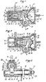
- the combined actuation device shown in FIGS. 1 to 3, generally identified by the reference 100, comprises a body 1 forming a cylinder housing 2 delimiting a cylindrical internal chamber 3 closed by a front end wall 4 of the housing 2, and a pump housing 5 flaring in the direction opposite to the front wall 4 and closed by a cover 6 made, like the body 1, of plastic material.
- a valve means 10 for example of the disc or membrane type made of elastomer, selectively obscuring radial orifices 11 establishing communication between the interior of the body 1 and the exterior: inside the chamber 3 axially extends a central appendage 12, formed in one piece with the bottom wall 4 and on the inner end of which is mounted, also co-axially, a stop disc 120.
- the body 1 also defines a transverse bearing surface 13 (FIG.
- a socket t ll etee 1 4 used for mounting the body 1 on any suitable support, for example a sheet 15 of a vehicle body, by means of a washer 16 and a nut 17.
- the socket 14 has an inner ring 18 forming a bearing for a shaft 19 of pheasant wiper arms t protrudes beyond the body 1 and bears, at its opposite end, in a blind surface 20 formed in the body 1.
- the end region of the shaft 19 has grooves 21 for mounting an arm 22 d headlight wiper held in place by a nut 23.
- annular piston 24 bearing in a sealed manner against the internal face of the jacket 7 but comprising an annular peripheral cavity 25 communicating, in the rest position, with the supply pipe 9, and , by radial holes 26, with the interior of the chamber 3.
- the end of the piston 24 directed towards the bottom wall 4 comprises, embedded in its mass, two elastic metallic tongues diametrically opposite, spotted 27, projecting axially towards the exterior and provided, in the vicinity of their free end, with openings in which are engaged the opposite ends of a bistable blade 28 of generally diamond-shaped configuration, pierced with a central hole through which extends appendix 12, produced for example from 0.1 mm thick blue sheet metal and capable of assuming two stable positions with inverted concavities shown in FIGS. 1 and 2.
- a piston head 29 coaxial with the latter, closing, on this side, by an end wall 30, the interior cavity 31 of the annular piston.
- the wall of the annular piston 24 is provided, immediately in front of the face 30 of the head 29, with radial orifices 32 capable of establishing communication between the internal cavity 31 and the periphery of the head 29.
- annular slide 33 comprising an annular peripheral chamber 34 extending over a part of its length.
- the end of the drawer 33 is thickened radially inwards to form an annular shoulder 35 capable of cooperating with the rear face 36 of the disc 120.
- This end of the drawer 33 is also extended by two diametrically opposite tabs 37 projecting towards the front wall 4 of the housing 2 and provided on their internal faces facing slots 38 forming two axially facing edges between which are received the opposite lateral ends of the bistable plate 28 and serving to urge the latter in the either of its two stable positions with opposite concavities.
- the head 29 of the piston 24 has an open recess 39 serving to accommodate one end of a link 40 provided with a roller 41 mounted idly on a transverse axis 42.
- the other end of the link 40 is fixed on the shaft 19 of the headlight wiper arm which is provided locally for this purpose with a knurled zone 43.
- an elastomer pump membrane 50 delimiting an interior chamber of liquid 51 communicating with the outside by a pipe 52 formed axially in one piece with the cover 6.
- a conical helical spring 53 bearing by its end of larger diameter against the cover 6 and, by its end of smaller diameter, against a recovery cup 54 profiled to correspond substantially to the end shape of the piston head 29 which is therefore biased to the left, as shown in FIGS. 1 and 2, by the spring 53 with the membrane 50 pressed between the cup 54 and the head 29 of the piston 24.
- the operation of the device is as follows: in the rest configuration shown in FIG. 1, the piston assembly is in a first extreme position, under the effect of the return force of the spring 53, that is to say say with the piston crew moved to the left and the chamber 51 of the pump having a maximum internal volume. Under these conditions, the radial orifices 32 of the annular piston 24 are internally masked by the right end of the drawer 33, the legs 37 of which abut against the bottom wall 4 of the body 1. On the other hand, the annular peripheral chamber 25 of the piston 24 communicates with the orifice 8 of the jacket 7 while the radial orifices 26 are unmasked by the left end of the drawer 33, the bistable blade 28 having the first configuration shown in FIG. 1.
- the tabs 37 of the drawer abut against the internal face 44 of the bottom 4 of the housing 2 while the piston 24 continues its movement, thus bringing the bistable blade 28 back to its first configuration in FIG. 1, that is to say with the slide 33 offset to the right with respect to the piston 24, thus again obscuring the radial orifices 32 and unmasking the radial orifices 26 to allow a new introduction of compressed air into the chamber 3 , the previously described process thus reproducing itself automatically.
- the link 40 causes an alternating angular displacement of the shaft 19 and therefore the sweeping of the wiping arm 22, while the membrane 50 periodically expels a measured quantity of liquid towards a nozzle, as we will see later.
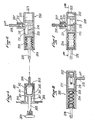
- FIG. 4 shows an installation of headlight washers / wipers arranged around two devices 100 previously described.
- the inlet pipes 9 are connected to a source of pressurized air R (for example a tank supplied, via a desiccator, by a vehicle compressor) via a distributor 200 controlled by a manual control device 300.
- the liquid supply and outlet pipes 52 of the devices 100 are connected to jets with non-return valves 400 in the vicinity of the headlight window to be cleaned and, by a conduit 501 provided at its immersed end with a non-return valve 502, to a washing liquid reservoir 500 not necessarily of the pressurized type.
- the manual control device 300 comprises a housing 301 defining an internal cavity 302 closed at one end by a cover 303 provided with a fluid pipe connection 304, the bottom wall of the housing 301 forming a flange 305 used for mounting the device on a wall 306 of a vehicle.
- the bottom wall also forms an internal tubular bearing 307 for an actuating rod 308 provided, at one end, with an actuating button 309 and, at its other end, with a plate 310 cooperating with a shaped membrane bell 311 clamped by its periphery between the cover 303 and the housing body 301 and defining a fluid cavity 312.
- the distributor 200 comprises a cylindrical body 201 defining an internal chamber 202 in which a piston 203 is mounted with sealed sliding action, an external face of which is linked to an extensible bellows 204 held in place in the cavity 202 by a cover 205 provided with a connector of fluid line 206.
- the body 201 also forms a lateral extension 207 in which is mounted a pressurized air inlet pipe connection 208 and defining an interior chamber whose bottom, communicating with the chamber 202, forms a seat for a valve head 209 integral with a rod 210 passing through the communication orifice and extending into an open housing 211 formed in the piston 203, the valve head 209 normally being held pressed against its seat by a spring 212 bearing against the internal end of the connector 208.
- the end of the chamber 202 opposite the bellows 204 communicates with the outside via an orifice 204.
- the housing 211 can be t also communicate with a compressed air outlet pipe fitting 213 formed laterally in the body 201.
- the housing 211 of the piston 203 has an internal ramp surface 214 capable of cooperating with the rod 210 of the valve 209.
Landscapes
- Engineering & Computer Science (AREA)
- Mechanical Engineering (AREA)
- General Engineering & Computer Science (AREA)
- Lighting Device Outwards From Vehicle And Optical Signal (AREA)
- Non-Portable Lighting Devices Or Systems Thereof (AREA)
Claims (7)
Applications Claiming Priority (2)
| Application Number | Priority Date | Filing Date | Title |
|---|---|---|---|
| FR8208797A FR2527151A1 (fr) | 1982-05-19 | 1982-05-19 | Dispositif pneumatique d'actionnement de bras pivotant d'essuie-vitre et installation combinee d'essuie-phares/lave-phares utilisant un tel dispositif |
| FR8208797 | 1982-05-19 |
Publications (2)
| Publication Number | Publication Date |
|---|---|
| EP0094862A1 EP0094862A1 (de) | 1983-11-23 |
| EP0094862B1 true EP0094862B1 (de) | 1986-08-13 |
Family
ID=9274210
Family Applications (1)
| Application Number | Title | Priority Date | Filing Date |
|---|---|---|---|
| EP83400887A Expired EP0094862B1 (de) | 1982-05-19 | 1983-05-03 | Pneumatischer Antrieb eines Scheibenwischerarms und kombinierte Wisch-/Wascheinrichtung für Scheinwerfer unter Verwendung eines solchen Antriebs |
Country Status (3)
| Country | Link |
|---|---|
| EP (1) | EP0094862B1 (de) |
| DE (1) | DE3365262D1 (de) |
| FR (1) | FR2527151A1 (de) |
Families Citing this family (1)
| Publication number | Priority date | Publication date | Assignee | Title |
|---|---|---|---|---|
| FR3107680B1 (fr) * | 2020-02-28 | 2024-11-29 | Valeo Systemes Dessuyage | Dispositif de nettoyage pour système optique |
Citations (3)
| Publication number | Priority date | Publication date | Assignee | Title |
|---|---|---|---|---|
| DE808413C (de) * | 1949-12-23 | 1951-07-16 | Westinghouse Bremsen Ges M B H | Luftdruckkolbenmotor fuer Fahrzeug-Scheibenwischer |
| DE2360250A1 (de) * | 1973-12-04 | 1975-06-05 | Knorr Bremse Gmbh | Scheibenwisch- und waschanlage |
| FR2325820A1 (fr) * | 1975-09-26 | 1977-04-22 | Atlantique Chantiers | Dispositif generateur de mouvement alternatif rectiligne |
Family Cites Families (4)
| Publication number | Priority date | Publication date | Assignee | Title |
|---|---|---|---|---|
| US3414186A (en) * | 1966-07-22 | 1968-12-03 | Jorgensen Poul | Transducer |
| FR2068374A5 (de) * | 1970-11-02 | 1971-08-20 | Dba | |
| DE2148192A1 (de) * | 1971-09-27 | 1973-04-05 | Alusuisse | Selbsttaetig oszillierender arbeitszylinder |
| FR2396180A2 (fr) * | 1977-06-30 | 1979-01-26 | Alsthom Atlantique | Perfectionnements apportes a un dispositif generateur d'un mouvement alternatif rectiligne |
-
1982
- 1982-05-19 FR FR8208797A patent/FR2527151A1/fr active Granted
-
1983
- 1983-05-03 DE DE8383400887T patent/DE3365262D1/de not_active Expired
- 1983-05-03 EP EP83400887A patent/EP0094862B1/de not_active Expired
Patent Citations (3)
| Publication number | Priority date | Publication date | Assignee | Title |
|---|---|---|---|---|
| DE808413C (de) * | 1949-12-23 | 1951-07-16 | Westinghouse Bremsen Ges M B H | Luftdruckkolbenmotor fuer Fahrzeug-Scheibenwischer |
| DE2360250A1 (de) * | 1973-12-04 | 1975-06-05 | Knorr Bremse Gmbh | Scheibenwisch- und waschanlage |
| FR2325820A1 (fr) * | 1975-09-26 | 1977-04-22 | Atlantique Chantiers | Dispositif generateur de mouvement alternatif rectiligne |
Also Published As
| Publication number | Publication date |
|---|---|
| FR2527151B1 (de) | 1984-12-21 |
| DE3365262D1 (en) | 1986-09-18 |
| EP0094862A1 (de) | 1983-11-23 |
| FR2527151A1 (fr) | 1983-11-25 |
Similar Documents
| Publication | Publication Date | Title |
|---|---|---|
| EP1284827B1 (de) | Membranpumpe | |
| EP2646294B1 (de) | Schaltung zur abgabe einer scheibenwaschflüssigkeit für ein kraftfahrzeug | |
| FR2675758A1 (fr) | Dispositif de lavage de la glace d'un projecteur de vehicule automobile. | |
| FR2834016A1 (fr) | Pompe a jet | |
| FR2656049A1 (fr) | Accumulateur de pression a piston, notamment pour systeme de freinage a regulation du glissement de traction. | |
| EP1606192B1 (de) | Abgabevorrichtung mit einer druckbetätigbaren pumpe | |
| EP0416966A2 (de) | Pneumatischer Servomotor | |
| EP0376815B1 (de) | Pumpe für kleine Mengen, insbesondere für die Schmierung einer Zweitaktbrennkraftmaschine | |
| FR2585414A1 (fr) | Pompe distributrice d'un fluide contenu dans un recipient | |
| EP1127624B1 (de) | Pumpe mit einer als Feder wirkenden Membrane and Behälter mit einer solchen Pumpe | |
| EP0094862B1 (de) | Pneumatischer Antrieb eines Scheibenwischerarms und kombinierte Wisch-/Wascheinrichtung für Scheinwerfer unter Verwendung eines solchen Antriebs | |
| EP1063018B1 (de) | Automatische Sprühpistole mit einer Membrane | |
| FR2862931A1 (fr) | Servofrein comportant un piston de decompression en materiau plastique integre a la tige de poussee. | |
| WO2000015479A1 (fr) | Dispositif perfectionne de projection de liquide de lavage et essuie-glace portant un tel dispositif | |
| EP2704928B1 (de) | Waschwasserausgabekreislauf für ein kraftfahrzeug und verfahren zum schutz eines solchen kreislaufes | |
| FR2682937A3 (en) | Device making it possible to draw off a liquid from a bottle and to dispense that liquid in sprayed form | |
| FR2653386A1 (de) | ||
| FR2805313A1 (fr) | Pompe hydraulique mue pneumatiquement | |
| FR2780105A3 (fr) | Compresseur | |
| FR2720044A1 (fr) | Dispositif à porte-gicleur escamotable pour le lavage de la glace d'un projecteur automobile. | |
| FR2849476A1 (fr) | Pompe a poussoir, notamment pour produit cosmetique | |
| FR2656041A1 (fr) | Pompe mecanique pour l'alimentation en carburant d'un moteur a combustion interne, en particulier pour installation a injection. | |
| FR2801646A3 (fr) | Pompe volumetrique alternative, en particulier pour la servocommande d'un embrayage de vehicule automobile | |
| EP4037940A1 (de) | Vorrichtung zur reinigung eines optischen systems | |
| EP1975021B1 (de) | Vorrichtung zum Reinigen einer transparenten oder spiegelnden Oberfläche, insbesondere des Scheinwerferglases eines Kraftfahrzeugs |
Legal Events
| Date | Code | Title | Description |
|---|---|---|---|
| PUAI | Public reference made under article 153(3) epc to a published international application that has entered the european phase |
Free format text: ORIGINAL CODE: 0009012 |
|
| 17P | Request for examination filed |
Effective date: 19830524 |
|
| AK | Designated contracting states |
Designated state(s): DE GB IT SE |
|
| RAP1 | Party data changed (applicant data changed or rights of an application transferred) |
Owner name: BENDIX FRANCE |
|
| ITF | It: translation for a ep patent filed | ||
| RAP1 | Party data changed (applicant data changed or rights of an application transferred) |
Owner name: BENDIX FRANCE |
|
| GRAA | (expected) grant |
Free format text: ORIGINAL CODE: 0009210 |
|
| AK | Designated contracting states |
Kind code of ref document: B1 Designated state(s): DE GB IT SE |
|
| REF | Corresponds to: |
Ref document number: 3365262 Country of ref document: DE Date of ref document: 19860918 |
|
| RAP2 | Party data changed (patent owner data changed or rights of a patent transferred) |
Owner name: SOCIETE DES CABLES DU MANS SOCIETE ANONYME |
|
| PLBE | No opposition filed within time limit |
Free format text: ORIGINAL CODE: 0009261 |
|
| STAA | Information on the status of an ep patent application or granted ep patent |
Free format text: STATUS: NO OPPOSITION FILED WITHIN TIME LIMIT |
|
| 26N | No opposition filed | ||
| ITPR | It: changes in ownership of a european patent |
Owner name: CESSIONE;SOCIETE DES CABLES DU MANS S.A. |
|
| PG25 | Lapsed in a contracting state [announced via postgrant information from national office to epo] |
Ref country code: DE Effective date: 19880202 |
|
| GBPC | Gb: european patent ceased through non-payment of renewal fee | ||
| PG25 | Lapsed in a contracting state [announced via postgrant information from national office to epo] |
Ref country code: SE Effective date: 19880504 |
|
| REG | Reference to a national code |
Ref country code: GB Ref legal event code: 732 |
|
| PG25 | Lapsed in a contracting state [announced via postgrant information from national office to epo] |
Ref country code: GB Free format text: LAPSE BECAUSE OF NON-PAYMENT OF DUE FEES Effective date: 19881122 |
|
| EUG | Se: european patent has lapsed |
Ref document number: 83400887.2 Effective date: 19890518 |