EP0094872A1 - Zweitaktbrennkraftmaschine mit Direkteinspritzung - Google Patents
Zweitaktbrennkraftmaschine mit Direkteinspritzung Download PDFInfo
- Publication number
- EP0094872A1 EP0094872A1 EP83400944A EP83400944A EP0094872A1 EP 0094872 A1 EP0094872 A1 EP 0094872A1 EP 83400944 A EP83400944 A EP 83400944A EP 83400944 A EP83400944 A EP 83400944A EP 0094872 A1 EP0094872 A1 EP 0094872A1
- Authority
- EP
- European Patent Office
- Prior art keywords
- channels
- cylinder
- casings
- motor according
- axis
- Prior art date
- Legal status (The legal status is an assumption and is not a legal conclusion. Google has not performed a legal analysis and makes no representation as to the accuracy of the status listed.)
- Granted
Links
- 238000002485 combustion reaction Methods 0.000 title claims description 9
- 238000002347 injection Methods 0.000 title claims description 7
- 239000007924 injection Substances 0.000 title claims description 7
- 230000006835 compression Effects 0.000 claims description 4
- 238000007906 compression Methods 0.000 claims description 4
- 238000004512 die casting Methods 0.000 claims description 3
- 239000000446 fuel Substances 0.000 claims description 3
- 239000000498 cooling water Substances 0.000 claims 1
- 238000003754 machining Methods 0.000 description 4
- 238000001816 cooling Methods 0.000 description 3
- 230000000694 effects Effects 0.000 description 2
- 239000000463 material Substances 0.000 description 2
- 238000007789 sealing Methods 0.000 description 2
- 239000000243 solution Substances 0.000 description 2
- XLYOFNOQVPJJNP-UHFFFAOYSA-N water Substances O XLYOFNOQVPJJNP-UHFFFAOYSA-N 0.000 description 2
- 229910000838 Al alloy Inorganic materials 0.000 description 1
- 230000015572 biosynthetic process Effects 0.000 description 1
- 238000005266 casting Methods 0.000 description 1
- 238000010276 construction Methods 0.000 description 1
- 239000012530 fluid Substances 0.000 description 1
- 238000005461 lubrication Methods 0.000 description 1
- 238000004519 manufacturing process Methods 0.000 description 1
- 230000004048 modification Effects 0.000 description 1
- 238000012986 modification Methods 0.000 description 1
- 238000000926 separation method Methods 0.000 description 1
- 238000010408 sweeping Methods 0.000 description 1
Images

Classifications
-
- F—MECHANICAL ENGINEERING; LIGHTING; HEATING; WEAPONS; BLASTING
- F02—COMBUSTION ENGINES; HOT-GAS OR COMBUSTION-PRODUCT ENGINE PLANTS
- F02F—CYLINDERS, PISTONS OR CASINGS, FOR COMBUSTION ENGINES; ARRANGEMENTS OF SEALINGS IN COMBUSTION ENGINES
- F02F7/00—Casings, e.g. crankcases
- F02F7/0021—Construction
- F02F7/0036—Casings for two-stroke engines with scavenging conduits
-
- F—MECHANICAL ENGINEERING; LIGHTING; HEATING; WEAPONS; BLASTING
- F02—COMBUSTION ENGINES; HOT-GAS OR COMBUSTION-PRODUCT ENGINE PLANTS
- F02F—CYLINDERS, PISTONS OR CASINGS, FOR COMBUSTION ENGINES; ARRANGEMENTS OF SEALINGS IN COMBUSTION ENGINES
- F02F1/00—Cylinders; Cylinder heads
- F02F1/18—Other cylinders
- F02F1/22—Other cylinders characterised by having ports in cylinder wall for scavenging or charging
-
- F—MECHANICAL ENGINEERING; LIGHTING; HEATING; WEAPONS; BLASTING
- F02—COMBUSTION ENGINES; HOT-GAS OR COMBUSTION-PRODUCT ENGINE PLANTS
- F02B—INTERNAL-COMBUSTION PISTON ENGINES; COMBUSTION ENGINES IN GENERAL
- F02B75/00—Other engines
- F02B75/02—Engines characterised by their cycles, e.g. six-stroke
- F02B2075/022—Engines characterised by their cycles, e.g. six-stroke having less than six strokes per cycle
- F02B2075/025—Engines characterised by their cycles, e.g. six-stroke having less than six strokes per cycle two
Definitions
- the present invention relates to internal combustion engines operating according to the two-stroke cycle and with direct fuel injection, of the type whose crankcase-cylinder comprises at least one cylinder into which open air intake channels controlled by the piston. associ ..
- the realization of the channels by coring does not make it possible to directly obtain from the foundry surface states compatible with good engine performance and therefore requires delicate machining operations which, on the one hand, limit the shape of the profile. longitudinal and of the section of the channels and, on the other hand, are generally impassable when the channels have come from the foundry in the cylinder block.
- German patent 46 ⁇ . 884 It is also known from the German patent 46 ⁇ . 884 to cut a cylinder block into two parts assembled along a plane perpendicular to the cylinder axis and passing through air intake channels, essentially for reasons of mounting around a jacket with projections partially constituting these channels and to remove hot spots and temperature gradients around the cylinder.
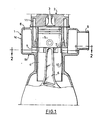
- the two-stroke engine shown is of the single-cylinder type, with compression ignition and direct injection of fuel into the combustion chamber, the injection system not having been shown for clarity of the drawing.
- This engine comprises a cylinder block 1 surmounted by a cylinder head 2 in which is housed an exhaust valve 3.
- a piston 5 articulated on a connecting rod 6 for driving a crankshaft (not shown ).
- the piston 5 masks and discovers air intake channels 7 which make the cylinder 4 communicate with an air cover 8 surrounding the cylinder 4 and in which, in operation, a compressor (not shown) expels air admitted through an inlet pipe 9.
- the cylinder 4 is delimited by a thin jacket 10 compressed over a small height and defining, with the cylinder block 1 and the cylinder head 2, a water chamber of cooling 11.
- the jacket 10 has, at the right of the channels 7, large openings 12 which each uncover the openings of several of the channels 7 and can thus be easily obtained by machining.
- the cylinder block 1 consists of two half-casings, namely an upper half-casing 1A and a lower half-casing 1B whose assembly plane (line 2-2 of FIG. 1 and line AA of FIG. 3) is perpendicular to the axis of the cylinder 4 and passes through the intake channels 7.
- the two half-casings are assembled by four long tie rods 13 which pass through bosses 14 of the half-casings 1A and 1B and are screwed at one of their ends into the cylinder head 2.
- the tie rods 13 thus put the half-casings in compression over their entire height and avoid the work in alternating traction of the least resistant parts of the casing 1.
- the execution of the cylinder block 1 in two half-casings makes it possible to produce the latter by die-casting and thus obtain, rough foundry and according to the best geometry, the air intake channels 7.
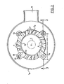
- These channels, considered in the assembly plane can be oriented angularly, for example substantially tangentially to a circle C concentric with the axis of the cylinder 4, as shown in FIG. 2, to generate the vortex favoring effective scanning. of the cylinder.
- these channels can, in the same plane, have a shape ensuring the best flow coefficient, for example by means of a leave 7A (FIG. 2) defining a flared inlet avoiding the separation of the air streams from the walls of the channels, tarpaulin side air 8.
- these channels may have the desired length necessary for the establishment of air streams opening into the cylinder at a speed and a direction capable of generating the vortex.
- the material used for the two half-casings 1A and 1B will be an aluminum alloy which, cast under pressure, will make it possible to obtain without modification the most varied shapes for the channels but, of course, the invention n is not limited to the use of this type of material.
- the two half-casings 1A and 1B once assembled, together form the air cover 8 in which the compressor delivers.
- This can interest the entire periphery of the engine, as in the example shown, or only part of it, and does not require any cover and gasket. Sealing also poses no particular problem, insofar as the cooling chamber 11 is limited to the upper half-casing 1A so as not to affect the assembly plane of the two half-casings and where the combustion chamber is delimited between the upper half-casing 1A, the piston 5 and the cylinder head 2, no joint is necessary between the two half-casings.
- the invention is not limited to the embodiment described above.
- a pressurized oil chamber can be provided in the lower half-casing 1B.
- This also offers possibilities for appropriate lubrication of the jacket, the piston and the rings.
- the invention can be applied to different modes of construction of two-stroke engines, whether they are with one or more cylinders, filled with a pump-caster or by compressor, with exhaust by lights or by valves. In all cases, the traditional lights being replaced by channels whose arrangement is without constraint, their shape, their section, their length, their number are no longer a function of machining possibilities and no longer hamper the designer in the search for the best flow.
- the invention makes it possible to obtain industrially at the lowest cost all the scanning effects sought to improve the filling and therefore the efficiency of the motors.
- it facilitates the obtaining of compact motors, mainly in the case where the sweeping is ensured by a compressor delivering in an air tank.
Landscapes
- Engineering & Computer Science (AREA)
- Chemical & Material Sciences (AREA)
- Combustion & Propulsion (AREA)
- Mechanical Engineering (AREA)
- General Engineering & Computer Science (AREA)
- Cylinder Crankcases Of Internal Combustion Engines (AREA)
- Fuel-Injection Apparatus (AREA)
Applications Claiming Priority (2)
| Application Number | Priority Date | Filing Date | Title |
|---|---|---|---|
| FR8208339A FR2526871B1 (fr) | 1982-05-13 | 1982-05-13 | Moteur a combustion interne a deux temps et a injection directe |
| FR8208339 | 1982-05-13 |
Publications (2)
| Publication Number | Publication Date |
|---|---|
| EP0094872A1 true EP0094872A1 (de) | 1983-11-23 |
| EP0094872B1 EP0094872B1 (de) | 1986-02-19 |
Family
ID=9273999
Family Applications (1)
| Application Number | Title | Priority Date | Filing Date |
|---|---|---|---|
| EP19830400944 Expired EP0094872B1 (de) | 1982-05-13 | 1983-05-10 | Zweitaktbrennkraftmaschine mit Direkteinspritzung |
Country Status (4)
| Country | Link |
|---|---|
| EP (1) | EP0094872B1 (de) |
| DE (1) | DE3362160D1 (de) |
| ES (1) | ES522314A0 (de) |
| FR (1) | FR2526871B1 (de) |
Citations (6)
| Publication number | Priority date | Publication date | Assignee | Title |
|---|---|---|---|---|
| DE460884C (de) * | 1927-06-11 | 1928-06-09 | Maschf Augsburg Nuernberg Ag | Zylinder fuer Zweitaktbrennkraftmaschinen |
| DE625796C (de) * | 1934-03-24 | 1936-02-15 | Buckau R Wolf Akt Ges Maschf | Zylinderblock fuer mehrzylindrige Zweitaktbrennkraftmaschinen |
| DE759359C (de) * | 1941-02-23 | 1954-10-11 | Kloeckner Humboldt Deutz Ag | Zylinder fuer Zweitaktbrennkraftmaschinen |
| GB1191572A (en) * | 1967-03-21 | 1970-05-13 | Fairbanks Morse Inc | A Compression-Ignition Type Engine. |
| FR2183394A5 (de) * | 1972-05-05 | 1973-12-14 | Peugeot & Renault | |
| FR2360757A1 (fr) * | 1976-08-02 | 1978-03-03 | Renault | Structure de moteur a combustion interne |
-
1982
- 1982-05-13 FR FR8208339A patent/FR2526871B1/fr not_active Expired
-
1983
- 1983-05-10 DE DE8383400944T patent/DE3362160D1/de not_active Expired
- 1983-05-10 EP EP19830400944 patent/EP0094872B1/de not_active Expired
- 1983-05-12 ES ES522314A patent/ES522314A0/es active Granted
Patent Citations (6)
| Publication number | Priority date | Publication date | Assignee | Title |
|---|---|---|---|---|
| DE460884C (de) * | 1927-06-11 | 1928-06-09 | Maschf Augsburg Nuernberg Ag | Zylinder fuer Zweitaktbrennkraftmaschinen |
| DE625796C (de) * | 1934-03-24 | 1936-02-15 | Buckau R Wolf Akt Ges Maschf | Zylinderblock fuer mehrzylindrige Zweitaktbrennkraftmaschinen |
| DE759359C (de) * | 1941-02-23 | 1954-10-11 | Kloeckner Humboldt Deutz Ag | Zylinder fuer Zweitaktbrennkraftmaschinen |
| GB1191572A (en) * | 1967-03-21 | 1970-05-13 | Fairbanks Morse Inc | A Compression-Ignition Type Engine. |
| FR2183394A5 (de) * | 1972-05-05 | 1973-12-14 | Peugeot & Renault | |
| FR2360757A1 (fr) * | 1976-08-02 | 1978-03-03 | Renault | Structure de moteur a combustion interne |
Also Published As
| Publication number | Publication date |
|---|---|
| ES8402907A1 (es) | 1984-02-16 |
| ES522314A0 (es) | 1984-02-16 |
| EP0094872B1 (de) | 1986-02-19 |
| FR2526871A1 (fr) | 1983-11-18 |
| DE3362160D1 (en) | 1986-03-27 |
| FR2526871B1 (fr) | 1985-06-21 |
Similar Documents
| Publication | Publication Date | Title |
|---|---|---|
| FR2479328A1 (fr) | Moteur a combustion interne a allumage par etincelle | |
| FR2707349A1 (fr) | Moteur à combustion interne à deux temps. | |
| EP0351420B1 (de) | Brennkraftmaschine mit kompressionszündung und veränderlichem volumen | |
| FR2501289A1 (fr) | Moteur a combustion interne a dispositif de transfert en boucle moulable sous pression | |
| EP0094872B1 (de) | Zweitaktbrennkraftmaschine mit Direkteinspritzung | |
| FR2668202A1 (fr) | Carter d'un moteur a combustion interne a pistons alternatifs. | |
| FR2671137A1 (fr) | Moteur a deux temps a balayage retarde du cylindre. | |
| FR2809453A1 (fr) | Moteur rotatif a palettes fonctionnant selon les memes cycles que les moteurs dits alternatifs | |
| CH642143A5 (en) | Intake/exhaust unit for a four-stroke internal combustion engine | |
| EP0983426B1 (de) | Brennkraftmaschine mit fremdzündung | |
| FR2579669A1 (fr) | Moteur a combustion interne a pistons alternatifs | |
| FR2855221A1 (fr) | Repartiteur d'admission pour moteur a combustion interne suralimente. | |
| EP0754268B1 (de) | Zweitakt dieselbrennkraftmaschine mit einem spiralförmigen luftanzugskanal | |
| FR2849108A1 (fr) | Moteur a combustion interne comportant des moyens pour faire varier l'intensite du swirl | |
| FR2545157A1 (fr) | Perfectionnement aux pistons utilises notamment dans les moteurs a deux temps | |
| FR2531139A1 (fr) | Dispositif de controle d'un circuit de gaz d'une chambre de combustion | |
| FR2750474A1 (fr) | Carter cylindres pour moteur a combustion interne | |
| FR2763996A1 (fr) | Moteur a combustion interne a allumage commande comportant trois soupapes par cylindre | |
| BE499892A (de) | ||
| BE424055A (de) | ||
| BE337894A (de) | ||
| FR2778694A1 (fr) | Moteur a combustion interne a allumage commande et a injection directe | |
| FR2886682A3 (fr) | Chambre de combustion d'un moteur diesel | |
| BE378399A (de) | ||
| FR2859244A1 (fr) | Piston pour moteur a combustion interne a allumage par compression |
Legal Events
| Date | Code | Title | Description |
|---|---|---|---|
| PUAI | Public reference made under article 153(3) epc to a published international application that has entered the european phase |
Free format text: ORIGINAL CODE: 0009012 |
|
| 17P | Request for examination filed |
Effective date: 19830613 |
|
| AK | Designated contracting states |
Designated state(s): DE GB IT NL SE |
|
| GRAA | (expected) grant |
Free format text: ORIGINAL CODE: 0009210 |
|
| AK | Designated contracting states |
Designated state(s): DE GB IT NL SE |
|
| ITF | It: translation for a ep patent filed | ||
| REF | Corresponds to: |
Ref document number: 3362160 Country of ref document: DE Date of ref document: 19860327 |
|
| PLBE | No opposition filed within time limit |
Free format text: ORIGINAL CODE: 0009261 |
|
| STAA | Information on the status of an ep patent application or granted ep patent |
Free format text: STATUS: NO OPPOSITION FILED WITHIN TIME LIMIT |
|
| 26N | No opposition filed | ||
| PGFP | Annual fee paid to national office [announced via postgrant information from national office to epo] |
Ref country code: DE Payment date: 19910315 Year of fee payment: 9 |
|
| PGFP | Annual fee paid to national office [announced via postgrant information from national office to epo] |
Ref country code: GB Payment date: 19910419 Year of fee payment: 9 |
|
| PGFP | Annual fee paid to national office [announced via postgrant information from national office to epo] |
Ref country code: SE Payment date: 19910425 Year of fee payment: 9 |
|
| ITTA | It: last paid annual fee | ||
| PGFP | Annual fee paid to national office [announced via postgrant information from national office to epo] |
Ref country code: NL Payment date: 19910531 Year of fee payment: 9 |
|
| PG25 | Lapsed in a contracting state [announced via postgrant information from national office to epo] |
Ref country code: GB Effective date: 19920510 |
|
| PG25 | Lapsed in a contracting state [announced via postgrant information from national office to epo] |
Ref country code: SE Effective date: 19920511 |
|
| PG25 | Lapsed in a contracting state [announced via postgrant information from national office to epo] |
Ref country code: NL Effective date: 19921201 |
|
| GBPC | Gb: european patent ceased through non-payment of renewal fee |
Effective date: 19920510 |
|
| NLV4 | Nl: lapsed or anulled due to non-payment of the annual fee | ||
| PG25 | Lapsed in a contracting state [announced via postgrant information from national office to epo] |
Ref country code: DE Effective date: 19930202 |
|
| EUG | Se: european patent has lapsed |
Ref document number: 83400944.1 Effective date: 19921204 |