EP0094896A2 - Adapteur vidéo - Google Patents
Adapteur vidéo Download PDFInfo
- Publication number
- EP0094896A2 EP0094896A2 EP83440004A EP83440004A EP0094896A2 EP 0094896 A2 EP0094896 A2 EP 0094896A2 EP 83440004 A EP83440004 A EP 83440004A EP 83440004 A EP83440004 A EP 83440004A EP 0094896 A2 EP0094896 A2 EP 0094896A2
- Authority
- EP
- European Patent Office
- Prior art keywords
- adapter
- base
- connection
- pins
- printed circuit
- Prior art date
- Legal status (The legal status is an assumption and is not a legal conclusion. Google has not performed a legal analysis and makes no representation as to the accuracy of the status listed.)
- Granted
Links
Images
Classifications
-
- H—ELECTRICITY
- H04—ELECTRIC COMMUNICATION TECHNIQUE
- H04N—PICTORIAL COMMUNICATION, e.g. TELEVISION
- H04N5/00—Details of television systems
- H04N5/76—Television signal recording
- H04N5/765—Interface circuits between an apparatus for recording and another apparatus
-
- H—ELECTRICITY
- H01—ELECTRIC ELEMENTS
- H01R—ELECTRICALLY-CONDUCTIVE CONNECTIONS; STRUCTURAL ASSOCIATIONS OF A PLURALITY OF MUTUALLY-INSULATED ELECTRICAL CONNECTING ELEMENTS; COUPLING DEVICES; CURRENT COLLECTORS
- H01R31/00—Coupling parts supported only by co-operation with counterpart
- H01R31/06—Intermediate parts for linking two coupling parts, e.g. adapter
Definitions
- the present invention relates to the field of connection devices between video recorder and television and allowing recording or reproduction operations, and relates to a video adapter intended for this purpose.
- connection cords having connectors at their ends.
- connection cords having connectors at their ends.
- any change of operation for example the passage from a recording to a reproduction, requires a modification of the connections, either by means of a second cord, either by disconnecting and reconnecting the cord.
- the present invention aims to overcome these drawbacks.
- a video adapter characterized in that it consists of a 6-pin socket for direct connection to a television or on a similar adapter by means of a 6-pin / 6-pin intermediate cord, which is provided with a printed circuit, and by two pairs of cords, each provided with a connector, each pair being intended for an input-output assembly , respectively sound and image, these cords being soldered on the printed circuit of the base.
- the base is provided with a contact carrier which can be equipped with any number of plug-in contacts which are connected by wiring to the connection pins, directly or by means of 'a connection reverser, so as to produce a scart adapter, or the like.
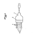
- the video adapter shown by way of example in FIG. 1 of the accompanying drawings, consists of a base 1 to 6 pins allowing direct connection to a television set or to an intermediate cord, and which is provided with a printed circuit. 2, and by two pairs of cords 3, which are each provided with a connector 4 for connection to a video recorder. These pairs of cords 3 are each provided to form an input-output assembly respectively for sound and image, and each cord 3 is soldered to the printed circuit 2 of the base 1.
- the printed circuit 2 allows the modulation of the sound and / or image, depending on the device to which the adapter is connected, by means of electronic components such as resistors, and the like.
- the base 1 can advantageously be equipped with an inverter for connecting the printed circuit 2. It is thus possible to make a copy from tape to tape by simple actuation of said inverter.
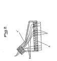
- the adapter comprises a pin base 5, which is provided with a contact holder 6 allowing the mounting of any number plug-in contacts 7.
- These contacts 7 are connected by wiring 8 to the connection pins 5, either directly, as indicated in FIG. 2, or by means of a connection reverser.
- the adapter thus formed can be plugged directly into the scart socket of a television and form a scart adapter, its base can be plugged into an intermediate cord having a corresponding number of plug pins.
- This adapter can obviously also be used in circuits other than video circuits, such as videotest, telematics, data processing, etc.
- the base 1 of the video adapter as well as the base 1 ′ of the scart adapter, or the like can be provided with any number of pins or connection contacts.
- these adapters can be used in conjunction with all types of pluggable intermediate cords.
- the invention it is possible to make a final connection of the adapter to the magnetos cope to perform all operations, namely recording by direct connection or copying by connection to an analog reverse adapter of another VCR.
Landscapes
- Engineering & Computer Science (AREA)
- Multimedia (AREA)
- Signal Processing (AREA)
- Details Of Connecting Devices For Male And Female Coupling (AREA)
Abstract
Description
- La présente invention concerne le domaine des dispositifs de connexion entre magnétoscope et téléviseur et permettant des opérations d'enregistrement ou de reproduction, et a pour objet un adaptateur vidéo destiné à cet effet.
- Actuellement, la connexion entre un téléviseur et un magnétoscope en vue de l'enregistrement, ou entre deux magnétoscopes est généralement effectuée au moyen de cordons de raccordement présentant à leurs extrémités des connecteurs. Cependant, l'utilisation de tels cordons ne permet qu'une seule opération, et tout changement d'opération, par exemple le passage d'un enregistrement à une reproduction, nécessite une modification des connexions, soit au moyen d'un deuxième cordon, soit par déconnexion et reconnexion du cordon.
- La présente invention a pour but de pallier ces inconvénients.
- Elle a, en effet, pour objet un adaptateur vidéo caractérisé en ce qu'il est constitué par un socle à 6 broches pour le branchement direct sur un téléviseur ou sur un adaptateur analogue au moyen d'un cordon intermédiaire 6 broches/6 broches, et qui est muni d'un circuit imprimé, et par deux paires de cordons munis chacun d'un connecteur, chaque paire étant destinée à un ensemble entrée-sortie, respectivement du son et de l'image, ces cordons étant soudés sur le circuit imprimé du socle.
- Conformément à une variante de réalisation de l'invention, le socle est muni d'un porte-contact pouvant être équipé d'un nombre quelconque de contacts enfichables qui sont reliés par un câblage aux broches de branchement, directement ou par l'intermédiaire d'un inverseur de branchement, de manière à réaliser un adaptateur de péritélévision, ou autre.
- L'invention sera mieux comprise grâce à la description ci-après, qui se rapporte à des modes de réalisation préférés, donnés à titre d'exemples non limitatifs, et expliqués avec référence aux dessins schématiques annexés, dans lesquels :
- la figure 1 est une vue en plan d'un adaptateur conforme à l'invention, et
- la figure 2 est une vue en coupe d'une variante de réalisation de l'invention.
- L'adaptateur vidéo représenté, à titre d'exemple à la figure 1 des dessins annexés est constitué d'un socle 1 à 6 broches permettant le branchement direct sur un téléviseur ou sur un cordon intermédiaire, et qui est muni d'un circuit imprimé 2, et par deux paires de cordons 3, qui sont pourvus chacun d'un connecteur 4 de branchement sur un magnétoscope. Ces paires de cordons 3 sont prévues chacune pour former un ensemble entrée-sortie respectivement pour le son et l'image, et chaque cordon 3 est soudé sur le circuit imprimé 2 du socle 1.
- Le circuit imprimé 2 permet la modulation du son et/ou de l'image, en fonction de l'appareil auquel est relié l'adaptateur, au moyen de composants électroniques tels que des résistances, et analogues.
- Conformément à une autre caractéristique de l'invention, le socle 1 peut avantageusement être équipé d'un inverseur du branchement du circuit imprimé 2. Il est ainsi possible de réaliser une copie de bande à bande par simple actionnement dudit inverseur.
- Selon une variante de réalisation de l'invention, et comme le montre la figure 2 des dessins annexés, l'adaptateur comporte un socle l'à broches 5, qui est muni d'un porte-contact 6 permettantle montage d'un nombre quelconque de contacts enfichables 7. Ces contacts 7 sont reliés par un câblage 8 aux broches de branchement 5, soit directement, comme indiqué sur la figure 2, soit par l'intermédiaire d'un inverseur de branchement.
- L'adaptateur ainsi constitué peut être branché directement sur la prise péritélévision d'un téléviseur et former un adaptateur de péritélévision, son socle pouvant être branché sur un cordon intermédiaire présentant un nombre de broches enfichables correspondant. Cet adaptateur peut évidemment également être utilisé dans des circuits autres que des circuits vidéo, tels que vidéotest, télématique, télé-informatique, etc.
- Conformément à une autre caractéristique de l'invention, le socle 1 de l'adaptateur vidéo,cainsi que le socle l' de l'adaptateur de péritélévision, ou autre peuvent être pourvus d'un nombre quelconque de broches ou de contacts de branchement. Ainsi, ces adaptateurs peuvent être utilisés en correspondance avec tous les types de cordons intermédiaires enfichables.
- Grâce à l'invention, il est possible de réaliser un branchement définitif de l'adaptateur sur le magnétoscope pour réaliser toutes les opérations, à savoir l'enregistrement par branchement direct ou la copie par branchement sur un adaptateur analogue inversé d'un autre magnétoscope. En outre, il est également possible de réaliser l'économie d'un nombre relativement important de câbles de connexions usuels actuellement et spécifiques chacun à une utilisation donnée.
- En outre, il est également possible de réaliser un branchement direct d'un système de péritélévision, ou autre système de connexion, sans nécessiter un montage complexe, tel que soudure ou verrouillage des fils d'un câble multicontact sur la fiche, au moyen d'un câble de liaison unique facilement interchangeable.
- Bien entendu, l'invention n'est pas limitée aux modes de réalisation décrits et représentés aux dessins annexés. Des modifications restent possibles, notamment du point de vue de la constitution des divers éléments, ou par substitution d'équivalents techniques, sans sortir pour autant du domaine de protection de l'invention.
Claims (4)
Priority Applications (1)
| Application Number | Priority Date | Filing Date | Title |
|---|---|---|---|
| AT83440004T ATE35885T1 (de) | 1982-05-13 | 1983-01-12 | Video adapter. |
Applications Claiming Priority (4)
| Application Number | Priority Date | Filing Date | Title |
|---|---|---|---|
| FR8208744 | 1982-05-13 | ||
| FR8208744A FR2527012B1 (fr) | 1982-05-13 | 1982-05-13 | Adaptateur video |
| FR8216499 | 1982-09-27 | ||
| FR8216499A FR2533762B2 (fr) | 1982-09-27 | 1982-09-27 | Adaptateur video |
Publications (3)
| Publication Number | Publication Date |
|---|---|
| EP0094896A2 true EP0094896A2 (fr) | 1983-11-23 |
| EP0094896A3 EP0094896A3 (en) | 1985-01-23 |
| EP0094896B1 EP0094896B1 (fr) | 1988-07-20 |
Family
ID=26222910
Family Applications (1)
| Application Number | Title | Priority Date | Filing Date |
|---|---|---|---|
| EP19830440004 Expired EP0094896B1 (fr) | 1982-05-13 | 1983-01-12 | Adapteur vidéo |
Country Status (2)
| Country | Link |
|---|---|
| EP (1) | EP0094896B1 (fr) |
| DE (2) | DE3377450D1 (fr) |
Cited By (2)
| Publication number | Priority date | Publication date | Assignee | Title |
|---|---|---|---|---|
| WO1986000771A1 (fr) * | 1984-07-06 | 1986-01-30 | Deutsche Thomson-Brandt Gmbh | Adaptateur audio/video pour des appareils audio-visuels |
| EP0293135A3 (fr) * | 1987-05-29 | 1991-01-30 | Sony Corporation | Adaptateur de câble comprenant un commutateur |
Family Cites Families (5)
| Publication number | Priority date | Publication date | Assignee | Title |
|---|---|---|---|---|
| US3747209A (en) * | 1969-11-12 | 1973-07-24 | Bunker Ramo | Automated wiring system and method |
| US4088384A (en) * | 1976-11-29 | 1978-05-09 | Northern Telecom Limited | Adaptor for plug-in telephones |
| US4188644A (en) * | 1976-12-23 | 1980-02-12 | Nelson Donald W | Apparatus for controlling video tape presentation |
| US4276562A (en) * | 1980-03-31 | 1981-06-30 | Mark Stewart | TV Switching system |
| DE3022363A1 (de) * | 1980-06-14 | 1981-12-24 | Eicke + Bemmerer Messtechnik oHG, 3000 Hannover | Umschalt- und verteilervorrichtung fuer audiovisuelle signale |
-
1983
- 1983-01-12 EP EP19830440004 patent/EP0094896B1/fr not_active Expired
- 1983-01-12 DE DE8383440004T patent/DE3377450D1/de not_active Expired
- 1983-02-09 DE DE19838303514 patent/DE8303514U1/de not_active Expired
Cited By (2)
| Publication number | Priority date | Publication date | Assignee | Title |
|---|---|---|---|---|
| WO1986000771A1 (fr) * | 1984-07-06 | 1986-01-30 | Deutsche Thomson-Brandt Gmbh | Adaptateur audio/video pour des appareils audio-visuels |
| EP0293135A3 (fr) * | 1987-05-29 | 1991-01-30 | Sony Corporation | Adaptateur de câble comprenant un commutateur |
Also Published As
| Publication number | Publication date |
|---|---|
| DE3377450D1 (en) | 1988-08-25 |
| EP0094896B1 (fr) | 1988-07-20 |
| DE8303514U1 (de) | 1984-08-02 |
| EP0094896A3 (en) | 1985-01-23 |
Similar Documents
| Publication | Publication Date | Title |
|---|---|---|
| US6524119B2 (en) | Connector adapted to handling of different kinds of signals including high-speed signals | |
| US6406313B1 (en) | Interchangeable connector system | |
| JPS629985B2 (fr) | ||
| KR970702477A (ko) | 프로그래밍이 가능한 케이블 어댑터(Programmable cable adaptor) | |
| US20220037834A1 (en) | Anti-Attenuation Apparatus | |
| US20070004255A1 (en) | Electrical cable connector assembly with dustproof means | |
| EP0094896A2 (fr) | Adapteur vidéo | |
| JPS59139582A (ja) | 電気導通装置 | |
| US4088382A (en) | Connecting structure of terminals | |
| NL8902862A (nl) | Connector met middelen voor het door klemmen verwezenlijken van contact met een geleider. | |
| FR2533762A2 (fr) | Adaptateur video | |
| JP3313074B2 (ja) | 変換コネクタ | |
| GB2237152A (en) | Pivoting component for flexible circuit | |
| FR2527012A1 (fr) | Adaptateur video | |
| EP0654847A1 (fr) | Elément de contact électrique | |
| EP0789426A1 (fr) | Composant de connexion pour des signaux vidéo | |
| US6692306B1 (en) | Extraction device for electrical connector | |
| FR2553235A3 (fr) | Derivation peritelevision | |
| EP1059706A1 (fr) | Dispositif de raccordement d'appareils ou de modules électroniques | |
| FR2861505A1 (fr) | Systeme de connexion sans soudure pour cartes a circuits imprimes | |
| DE59407677D1 (de) | Anschlussmodul | |
| FR2587850A1 (fr) | Embase pour connecteur de peritelevision | |
| FR2524723A1 (fr) | Connecteur pour branchement de postes telephoniques et terminaux telematiques | |
| JPH05110143A (ja) | 簡易光モジユール | |
| JPH07282918A (ja) | フレキシブル配線板接続装置 |
Legal Events
| Date | Code | Title | Description |
|---|---|---|---|
| PUAI | Public reference made under article 153(3) epc to a published international application that has entered the european phase |
Free format text: ORIGINAL CODE: 0009012 |
|
| AK | Designated contracting states |
Designated state(s): AT BE CH DE GB IT LI LU NL SE |
|
| PUAL | Search report despatched |
Free format text: ORIGINAL CODE: 0009013 |
|
| AK | Designated contracting states |
Designated state(s): AT BE CH DE GB IT LI LU NL SE |
|
| 17P | Request for examination filed |
Effective date: 19850102 |
|
| 17Q | First examination report despatched |
Effective date: 19860602 |
|
| D17Q | First examination report despatched (deleted) | ||
| GRAA | (expected) grant |
Free format text: ORIGINAL CODE: 0009210 |
|
| AK | Designated contracting states |
Kind code of ref document: B1 Designated state(s): AT BE CH DE GB IT LI LU NL SE |
|
| REF | Corresponds to: |
Ref document number: 35885 Country of ref document: AT Date of ref document: 19880815 Kind code of ref document: T |
|
| REF | Corresponds to: |
Ref document number: 3377450 Country of ref document: DE Date of ref document: 19880825 |
|
| ITF | It: translation for a ep patent filed | ||
| GBT | Gb: translation of ep patent filed (gb section 77(6)(a)/1977) | ||
| PGFP | Annual fee paid to national office [announced via postgrant information from national office to epo] |
Ref country code: NL Payment date: 19890131 Year of fee payment: 11 |
|
| PLBI | Opposition filed |
Free format text: ORIGINAL CODE: 0009260 |
|
| 26 | Opposition filed |
Opponent name: UNI- STECK GMBH & CO. KG Effective date: 19890419 Opponent name: HAMA HAMAPHOT KG HANKE & THOMAS Effective date: 19890419 Opponent name: HEINRICH ZEHNDER GMBH Effective date: 19890418 |
|
| PLAB | Opposition data, opponent's data or that of the opponent's representative modified |
Free format text: ORIGINAL CODE: 0009299OPPO |
|
| NLR1 | Nl: opposition has been filed with the epo |
Opponent name: UNI- STECK GMBH & CO. KG Opponent name: HAMA HAMAPHOT KG HANKE & THOMAS Opponent name: HEINRICH ZEHNDER GMBH |
|
| PLAB | Opposition data, opponent's data or that of the opponent's representative modified |
Free format text: ORIGINAL CODE: 0009299OPPO |
|
| R26 | Opposition filed (corrected) |
Opponent name: HEINRICH ZEHNDER GMBH * 890419 HAMA HAMAPHOT KG HA Effective date: 19890418 |
|
| R26 | Opposition filed (corrected) |
Opponent name: HEINRICH ZEHNDER GMBH * 890419 HAMA HAMAPHOT KG HA Effective date: 19890418 |
|
| PGFP | Annual fee paid to national office [announced via postgrant information from national office to epo] |
Ref country code: GB Payment date: 19911231 Year of fee payment: 10 |
|
| PGFP | Annual fee paid to national office [announced via postgrant information from national office to epo] |
Ref country code: SE Payment date: 19920117 Year of fee payment: 10 |
|
| PGFP | Annual fee paid to national office [announced via postgrant information from national office to epo] |
Ref country code: LU Payment date: 19920130 Year of fee payment: 10 Ref country code: BE Payment date: 19920130 Year of fee payment: 10 |
|
| ITTA | It: last paid annual fee | ||
| PGFP | Annual fee paid to national office [announced via postgrant information from national office to epo] |
Ref country code: DE Payment date: 19920227 Year of fee payment: 10 |
|
| PGFP | Annual fee paid to national office [announced via postgrant information from national office to epo] |
Ref country code: CH Payment date: 19920429 Year of fee payment: 10 |
|
| EPTA | Lu: last paid annual fee | ||
| PGFP | Annual fee paid to national office [announced via postgrant information from national office to epo] |
Ref country code: AT Payment date: 19921127 Year of fee payment: 11 |
|
| RDAG | Patent revoked |
Free format text: ORIGINAL CODE: 0009271 |
|
| STAA | Information on the status of an ep patent application or granted ep patent |
Free format text: STATUS: PATENT REVOKED |
|
| 27W | Patent revoked |
Effective date: 19921209 |
|
| GBPR | Gb: patent revoked under art. 102 of the ep convention designating the uk as contracting state |
Free format text: 921209 |
|
| REG | Reference to a national code |
Ref country code: CH Ref legal event code: PL |
|
| BERE | Be: lapsed |
Owner name: ATELIERS SANDVALE S.A.R.L. Effective date: 19930131 |
|
| NLR2 | Nl: decision of opposition | ||
| EUG | Se: european patent has lapsed |
Ref document number: 83440004.6 Effective date: 19930623 |
|
| APAH | Appeal reference modified |
Free format text: ORIGINAL CODE: EPIDOSCREFNO |
|
| PLAB | Opposition data, opponent's data or that of the opponent's representative modified |
Free format text: ORIGINAL CODE: 0009299OPPO |