EP0094928A2 - Dispositif de déchargement pour un four à cuve - Google Patents
Dispositif de déchargement pour un four à cuve Download PDFInfo
- Publication number
- EP0094928A2 EP0094928A2 EP83890059A EP83890059A EP0094928A2 EP 0094928 A2 EP0094928 A2 EP 0094928A2 EP 83890059 A EP83890059 A EP 83890059A EP 83890059 A EP83890059 A EP 83890059A EP 0094928 A2 EP0094928 A2 EP 0094928A2
- Authority
- EP
- European Patent Office
- Prior art keywords
- lock chamber
- cellular wheel
- discharge device
- wheel
- furnace
- Prior art date
- Legal status (The legal status is an assumption and is not a legal conclusion. Google has not performed a legal analysis and makes no representation as to the accuracy of the status listed.)
- Granted
Links
- 238000007599 discharging Methods 0.000 title description 2
- 230000001413 cellular effect Effects 0.000 claims abstract description 68
- 238000007789 sealing Methods 0.000 claims abstract description 35
- 210000002421 cell wall Anatomy 0.000 claims abstract description 20
- 239000000463 material Substances 0.000 claims abstract description 20
- 210000004027 cell Anatomy 0.000 claims abstract description 15
- 239000002826 coolant Substances 0.000 claims description 4
- 239000007789 gas Substances 0.000 description 38
- XEEYBQQBJWHFJM-UHFFFAOYSA-N Iron Chemical compound [Fe] XEEYBQQBJWHFJM-UHFFFAOYSA-N 0.000 description 4
- 230000002093 peripheral effect Effects 0.000 description 4
- 230000004888 barrier function Effects 0.000 description 3
- 238000001816 cooling Methods 0.000 description 3
- 230000000694 effects Effects 0.000 description 3
- 239000011261 inert gas Substances 0.000 description 2
- 238000009413 insulation Methods 0.000 description 2
- 229910052742 iron Inorganic materials 0.000 description 2
- 230000000149 penetrating effect Effects 0.000 description 2
- 230000000717 retained effect Effects 0.000 description 2
- 239000010425 asbestos Substances 0.000 description 1
- 239000000110 cooling liquid Substances 0.000 description 1
- 239000000498 cooling water Substances 0.000 description 1
- 230000007423 decrease Effects 0.000 description 1
- 230000007812 deficiency Effects 0.000 description 1
- 230000006735 deficit Effects 0.000 description 1
- 239000000428 dust Substances 0.000 description 1
- 230000002349 favourable effect Effects 0.000 description 1
- 230000002452 interceptive effect Effects 0.000 description 1
- 239000000203 mixture Substances 0.000 description 1
- 230000003647 oxidation Effects 0.000 description 1
- 238000007254 oxidation reaction Methods 0.000 description 1
- 230000005855 radiation Effects 0.000 description 1
- 238000004064 recycling Methods 0.000 description 1
- 229910052895 riebeckite Inorganic materials 0.000 description 1
- XLYOFNOQVPJJNP-UHFFFAOYSA-N water Substances O XLYOFNOQVPJJNP-UHFFFAOYSA-N 0.000 description 1
Images


Classifications
-
- F—MECHANICAL ENGINEERING; LIGHTING; HEATING; WEAPONS; BLASTING
- F27—FURNACES; KILNS; OVENS; RETORTS
- F27B—FURNACES, KILNS, OVENS OR RETORTS IN GENERAL; OPEN SINTERING OR LIKE APPARATUS
- F27B1/00—Shaft or like vertical or substantially vertical furnaces
- F27B1/10—Details, accessories or equipment specially adapted for furnaces of these types
- F27B1/21—Arrangements of devices for discharging
-
- C—CHEMISTRY; METALLURGY
- C21—METALLURGY OF IRON
- C21B—MANUFACTURE OF IRON OR STEEL
- C21B13/00—Making spongy iron or liquid steel, by direct processes
- C21B13/02—Making spongy iron or liquid steel, by direct processes in shaft furnaces
Definitions
- the invention relates to a discharge device for a shaft furnace, consisting of a lock chamber connected to the shaft furnace by means of a delivery line, in which a rotor receiving the furnace material and closing the lock chamber inlet from the lock chamber outlet is drivably mounted.
- lock chambers are provided via a delivery line connected to the shaft furnace, in which a rotor consisting of a drum is rotatably mounted.
- This drum has a passage opening in a circumferential area for receiving or delivering the furnace material. If the passage opening of the drum matches the lock chamber inlet, material is brought into the drum from the shaft furnace.
- the lock chamber inlet is closed by the drum jacket and the lock chamber outlet is opened when the passage opening in the drum jacket reaches the area of the lock chamber outlet, and the furnace material can fall out of the drum through the lock chamber outlet.
- the main disadvantage of this arrangement of a drum is that the furnace material cannot be conveyed continuously through the lock chamber and that there is no security against undesired escape of furnace gas through the lock chamber.
- the rotation of the drum means that no material is conveyed between the lock chamber inlet and outlet, because the furnace material is either rotated with the drum or rolls on the inside wall of the drum.
- the invention is therefore based on the object of avoiding these deficiencies and improving a discharge device of the type described at the outset in such a way that a continuous discharge of material is ensured with a comparatively high throughput capacity, without the risk of furnace gas escaping.
- the invention solves this problem in that the rotor consists of a cellular wheel with star-shaped cell walls, that the delivery line is connected to a sealing gas pressure source and that Lock chamber between the lock chamber inlet and the lock chamber outlet has an exhaust pipe in the delivery area of the cellular wheel.
- a simply constructed, continuously operating pressure lock is obtained without having to accept pressure loss in the furnace.
- the sealing gas introduced into the delivery line between the delivery device and the lock chamber which must have at least a pressure corresponding to the pressure of the furnace gas, prevents furnace gas from penetrating as far as the lock chamber.
- the lock chamber between the lock chamber inlet and the lock chamber outlet in the delivery area of the cellular wheel is connected to an exhaust gas line, via which the sealing gas entering the lock chamber can be discharged.
- the necessary pressure reduction in the lock chamber is based on the fact that the cell walls connect to the peripheral wall of the lock chamber and form a seal between the lock chamber inlet and the lock chamber outlet. Since this closure, however, cannot be completely gas-tight because of the necessary play between the cell wheel and the lock chamber, the sealing gas is also counter to the conveying direction of the cell. Rades penetrate into the lock chamber between the cell walls of the feeder and the lock chamber wall. In order to prevent this sealing gas component from escaping from the lock chamber, an exhaust pipe can also be connected to the lock chamber between the lock chamber inlet and the lock chamber outlet in the return area of the cellular wheel.
- the angular distance between two successive cell walls of the cellular wheel is selected to be smaller than the angular spacing of the exhaust pipes on the one hand from the lock chamber inlet and on the other hand from the lock chamber outlet, then in each rotational position of the cellular wheel there is at least one cell wall between the exhaust pipes and the lock chamber inlet or the lock chamber outlet, which leads to the required interruptions of the otherwise possible flow paths.
- the sealing of the lock chamber between the lock chamber outlet and the exhaust pipes is of particular importance.
- the angular distance between the exhaust gas lines and the lock chamber outlet can be chosen to be greater than twice the angular distance between two successive cell walls, so that at least two cell walls are located between the exhaust gas lines and the lock chamber outlet in each Rotary position of the cellular wheel are.
- the cellular wheel Since, according to the invention, the cellular wheel is not used for metering purposes, but rather for closing a lock chamber as gas-tight as possible, the cell walls of the cellular wheel must be brought close to the lock chamber wall.
- the associated different thermal expansions must not call into question the rotatability of the cellular wheel, so that sufficient expansion play must be provided between the cellular wheel and the lock chamber, especially with regard to starting from the cold state up to the full operating temperature.
- the axial expansion play of the cellular wheel relative to the lock chamber can remain irrelevant for the gas-tight closure of the lock chamber by the cellular wheel if the cellular wheel consists of two end disks between which the cell walls are inserted. These end disks close the cell chambers in a gas-tight manner in the axial direction, so that no consideration has to be taken of connecting the cell walls to the end walls of the lock chamber.
- the end disks of the cellular wheel can consequently be at a distance of the thermal expansion of the cellular wheel relative to the lock chamber the end walls of the lock chamber can be arranged without sacrificing the tightness of the lock.
- the end disks of the cellular wheel in a further embodiment of the invention carry at least one ring flange projecting against the end wall of the lock chamber, which overlaps a counter flange on the end wall of the lock chamber to form a sealing gap on the outside.
- the axial expansion possibility of the cellular wheel is not restricted by this closure of the end space between the cellular wheel and the lock chamber. Because of the arrangement of the ring flange on the cell wheel outside the counter flange of the lock chamber, the radial expansion possibility of the cell wheel is also fully retained, because due to the higher temperature of the cell wheel, the cell wheel will expand more than the lock chamber.
- the sealing gap between the ring flanges and the counter flanges which increases when the pressure lock is approached with the temperature difference between the cellular wheel and the lock chamber, decreases again when the operating temperature is reached, when the temperature difference between the cellular wheel and the lock chamber becomes smaller.
- the high temperature of the furnace material which should be conveyed through the lock chamber without any loss of heat, requires a comparatively high thermal load on the bearings for the shaft of the cellular wheel.
- at least one ring channel for a coolant can be provided between the lock chamber and the shaft of the cellular wheel on the side of the bearings for the shaft of the cellular wheel facing the cellular wheel. This measure not only allows the bearing temperature to be reduced, but also provides additional security against leakage gas leakage via the shaft bearings. Particularly favorable conditions are created if two ring channels are provided axially one behind the other in order to carry out step-by-step cooling first with a cold inert gas and then with a cooling liquid, for example water.
- the lock chamber carries an annular flange projecting axially against the front disk, which overlaps a counter flange on the front disk with the interposition of a sealing slide ring on the outside, so it becomes very simple Design conditions ensured without endangering the tight seal of the ring channel with respect to the lock chamber by the necessary expansion possibility of the cellular wheel with respect to the lock chamber.
- the expansion of the cellular wheel relative to the lock chamber causes the slide ring clamped between the flanges to compress, which accordingly has to yield elastically. Due to the greater pressing force on the slide ring, the tight seal of the ring channel is even increased.
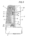
- the conveying device for discharging the hot furnace material is connected via a conveyor line 1 to a lock chamber 2 in which a cellular wheel 3 is drivably mounted.
- This cellular wheel 3 consists of two end disks 5 seated on a shaft 4, between which the cell walls 6 are inserted.
- the arrangement is such that the front disks 5 are provided with an axial distance from the end walls 7 of the lock chamber 2, during the radial Gap 8 (see in particular Fig.
- the annular space 10 which results between the end walls 7 of the lock chamber 2 and the front disks 5 of the cellular wheel 3 is closed off in the area of the outer circumference of the cellular wheel 3 by a gap seal which consists of two annular flanges 11 arranged at a radial distance from one another on the front disks 5 of the cellular wheel 3 and two corresponding counter flanges 12 is formed on the end walls 7 of the lock chamber 2.
- annular channels 15 and 16 are provided on the side of the bearing 14 facing the cellular wheel 3 between the lock chamber 2 and the shaft 4, into which a coolant can be introduced.
- the lock chamber 2 in each case forms an annular flange 17 projecting axially against the front disk 5, which overlaps a counter flange 18 on the front disk 5 of the cellular wheel 3 on the outside at a radial distance, between the ring flange 17 and the Counter flange 18 is a sealing ring 19 is used sealingly, which consists for example of a graphite-asbestos mixture.
- the coolant which consists of a cold inert gas and is introduced into the annular space 15 via lines 20, dissipates the absorbed heat via the lines 21.
- the annular channel 16, which is separated from the annular channel 15, is filled via the supply lines 22 with cooling water which is discharged via an axial bore 24 of the shaft 4 connected to the annular channel 16 by radial bores 23.
- the axial bore 24 is extended by an extension tube 26 which slidably engages in a connecting piece 25.
- a graded cooling system is available to dissipate the heat, the permissible one Operating temperatures for the bearings 14 of the shaft 4 of the cellular wheel 3 guaranteed.
- the delivery line 1 is connected to a sealing gas pressure source by means of a pipe connection 27, so that a sealing gas pressure greater than the furnace gas pressure can be built up in the delivery line 1.
- the barrier gas pressure must be reduced within the lock chamber 2 in order to largely prevent the barrier gas from escaping from the lock chamber 2. This is effected with the aid of the cellular wheel 3, an exhaust line 30 being provided between the lock chamber inlet 28 and the lock chamber outlet 29 both in the delivery area of the cellular wheel 3 and in the opposite return area, which leads the sealing gas penetrating into the lock chamber 2 into an existing gas circuit. Since the sealing gas has to be heated in order to avoid cooling of the furnace material, recycling the sealing gas is of considerable economic importance.
- the flow path between the lock chamber inlet 28 and the exhaust pipes 30 must therefore always be interrupted by at least one cell wall 6.
- the angular distance Oc between two successive cell walls 6 of the cellular wheel 3 is to be chosen smaller than the angular distances ⁇ of the exhaust pipes 30 from the lock chamber inlet 28.
- the same condition applies to the angular distance of the exhaust pipes 30 from the lock chamber outlet 29 to to prevent a sealing gas passage to the lock chamber outlet 29. If there are two or more cell walls between the exhaust gas lines 30 and the lock chamber outlet 29, the security against an undesired sealing gas outlet is increased.
- the cellular wheel 3 which can be driven via a chain wheel 31, conveys the hot furnace material through the lock chamber 2, whereby due to the completion of the free passage between the lock chamber inlet 28 and the lock chamber outlet 29 through the cellular wheel 3, a certain barrier pressure in the region of the delivery line 1 can be maintained.
- the lock chamber 2 receiving the cellular wheel 3 consequently acts as a pressure lock, which allows the hot furnace material to pass through, so that a continuous furnace discharge can be ensured without having to fear discharge of the furnace gas.
- the lock chamber 2 has a corresponding thermal insulation 32, which, however, cannot prevent a temperature difference between the cell wheel 3 and the lock chamber 2, which occurs in particular when the pressure lock is started from the cold Condition becomes noticeable by subjecting the cellular wheel 3 to greater thermal expansion. This greater thermal expansion is compensated for by appropriate expansion compensation without endangering the lock effect.
Landscapes
- Engineering & Computer Science (AREA)
- Chemical & Material Sciences (AREA)
- Manufacturing & Machinery (AREA)
- Materials Engineering (AREA)
- Metallurgy (AREA)
- Organic Chemistry (AREA)
- Mechanical Engineering (AREA)
- General Engineering & Computer Science (AREA)
- Muffle Furnaces And Rotary Kilns (AREA)
- Furnace Details (AREA)
- Vertical, Hearth, Or Arc Furnaces (AREA)
Applications Claiming Priority (2)
| Application Number | Priority Date | Filing Date | Title |
|---|---|---|---|
| AT1958/82 | 1982-05-18 | ||
| AT0195882A AT374275B (de) | 1982-05-18 | 1982-05-18 | Austragungsvorrichtung fuer einen schachtofen |
Publications (3)
| Publication Number | Publication Date |
|---|---|
| EP0094928A2 true EP0094928A2 (fr) | 1983-11-23 |
| EP0094928A3 EP0094928A3 (en) | 1984-04-18 |
| EP0094928B1 EP0094928B1 (fr) | 1986-07-30 |
Family
ID=3524722
Family Applications (1)
| Application Number | Title | Priority Date | Filing Date |
|---|---|---|---|
| EP83890059A Expired EP0094928B1 (fr) | 1982-05-18 | 1983-04-20 | Dispositif de déchargement pour un four à cuve |
Country Status (6)
| Country | Link |
|---|---|
| US (1) | US4507079A (fr) |
| EP (1) | EP0094928B1 (fr) |
| JP (1) | JPS58213180A (fr) |
| AT (1) | AT374275B (fr) |
| CA (1) | CA1212541A (fr) |
| DE (1) | DE3364880D1 (fr) |
Cited By (2)
| Publication number | Priority date | Publication date | Assignee | Title |
|---|---|---|---|---|
| EP0652055A1 (fr) * | 1993-10-07 | 1995-05-10 | IN.TEC. ITALIA INTERNATIONAL ENVIRONMENT TECHNOLOGY S.r.l. | Appareil et procédé pour le prétraitement de ferrailles électroniques |
| AT14432U1 (de) * | 2014-06-05 | 2015-11-15 | Binder Co Ag | Verfahren zur Expansion von sandkornförmigem Rohmaterial |
Families Citing this family (2)
| Publication number | Priority date | Publication date | Assignee | Title |
|---|---|---|---|---|
| AT382712B (de) * | 1985-05-10 | 1987-04-10 | Voest Alpine Ag | Beschickungsvorrichtung fuer einen schachtofen zum brennen von karbonathaltigem, mineralischem brenngut |
| JP3623016B2 (ja) * | 1995-06-09 | 2005-02-23 | 株式会社チサキ | 竪型焼成炉 |
Family Cites Families (12)
| Publication number | Priority date | Publication date | Assignee | Title |
|---|---|---|---|---|
| DE333699C (de) * | 1919-07-29 | 1921-03-03 | Fried Krupp Akt Ges | Entleerungsvorrichtung fuer unter Druck stehende Schachtoefen, Silos o. dgl. |
| DE337622C (de) * | 1919-11-05 | 1921-06-03 | Arno Andreas | Umlaufende Entleerungstrommel fuer Schachtoefen |
| DE338413C (de) * | 1919-12-13 | 1921-06-17 | Arno Andreas | Umlaufende Entleerungstrommel fuer Schachtoefen |
| DE345027C (de) * | 1920-12-24 | 1921-12-05 | Arno Andreas | Umlaufende Entleerungstrommel fuer Schachtoefen |
| US1850009A (en) * | 1928-05-23 | 1932-03-15 | Gronwall Eugen Assar Alexis | Reduction of metals out of their ores |
| DE545354C (de) * | 1929-04-24 | 1932-02-29 | William Henry Smith | Verfahren und Vorrichtung zum Reduzieren von Erzen, insbesondere Eisenerzen |
| US2072450A (en) * | 1932-05-13 | 1937-03-02 | Philadelphia & Reading Coal & | Furnace |
| DE1272945B (de) * | 1959-10-20 | 1968-07-18 | Metallurg D Imphy Soc | Verfahren zum unmittelbaren Reduzieren von zerkleinertem Eisenerz |
| FR1374753A (fr) * | 1963-11-13 | 1964-10-09 | Dispositif d'alimentation pour four | |
| IL28679A (en) * | 1966-09-28 | 1971-04-28 | Anglo Amer Corp South Africa | Ore segregation process |
| US3850616A (en) * | 1973-10-29 | 1974-11-26 | Armco Steel Corp | Inert gas seal for product discharge from a shaft furnace |
| US4073629A (en) * | 1974-07-30 | 1978-02-14 | Kamyr Inc. | Coal gasification process with improved procedure for continuously discharging ash particles and apparatus therefor |
-
1982
- 1982-05-18 AT AT0195882A patent/AT374275B/de not_active IP Right Cessation
-
1983
- 1983-04-20 DE DE8383890059T patent/DE3364880D1/de not_active Expired
- 1983-04-20 EP EP83890059A patent/EP0094928B1/fr not_active Expired
- 1983-05-10 US US06/493,204 patent/US4507079A/en not_active Expired - Fee Related
- 1983-05-17 CA CA000428307A patent/CA1212541A/fr not_active Expired
- 1983-05-17 JP JP58085195A patent/JPS58213180A/ja active Pending
Cited By (3)
| Publication number | Priority date | Publication date | Assignee | Title |
|---|---|---|---|---|
| EP0652055A1 (fr) * | 1993-10-07 | 1995-05-10 | IN.TEC. ITALIA INTERNATIONAL ENVIRONMENT TECHNOLOGY S.r.l. | Appareil et procédé pour le prétraitement de ferrailles électroniques |
| US5522153A (en) * | 1993-10-07 | 1996-06-04 | Celi; Antonio M. | Device and process for pre-treating electronic circuit scraps |
| AT14432U1 (de) * | 2014-06-05 | 2015-11-15 | Binder Co Ag | Verfahren zur Expansion von sandkornförmigem Rohmaterial |
Also Published As
| Publication number | Publication date |
|---|---|
| EP0094928B1 (fr) | 1986-07-30 |
| ATA195882A (de) | 1983-08-15 |
| DE3364880D1 (en) | 1986-09-04 |
| AT374275B (de) | 1984-04-10 |
| JPS58213180A (ja) | 1983-12-12 |
| CA1212541A (fr) | 1986-10-14 |
| US4507079A (en) | 1985-03-26 |
| EP0094928A3 (en) | 1984-04-18 |
Similar Documents
| Publication | Publication Date | Title |
|---|---|---|
| DE3030686C2 (fr) | ||
| DE4110114C2 (fr) | ||
| DE4216166A1 (de) | Vorrichtung zur kuehlung einer verteilerschurre einer schachtofen-beschickungsanlage | |
| DE3343299C2 (de) | Absperrschieber für Rohrleitungen großer Nennweiten, insbesondere Heißwindleitungen | |
| DE2840097A1 (de) | Einrichtung zur rueckgewinnung von waerme aus heissen abgasen | |
| AT506459A2 (de) | Vorrichtung und verfahren zur reinigung von schadstoffhaltigem abgas | |
| EP0094928B1 (fr) | Dispositif de déchargement pour un four à cuve | |
| DE2414053A1 (de) | Verfahren zum betrieb einer gasdynamischen druckwellenmaschine und einrichtung zur durchfuehrung des verfahrens | |
| DE3014574C2 (de) | Austragvorrichtung für Kokstrockenkühlkammern | |
| DE19628383A1 (de) | Ofen zur Wärmebehandlung von Chargen metallischer Werkstücke | |
| DE2300794A1 (de) | Kernreaktor | |
| DE102008011749B4 (de) | Toreinheit sowie Hochtemperaturofen mit einer solchen | |
| WO2018206383A1 (fr) | Transport d'un produit à transporter | |
| DE3205501C2 (fr) | ||
| DE3939170C2 (de) | Verschlußklappe für einen Schachtofen | |
| DE2409818A1 (de) | Verfahren zur waermebehandlung von eisenund nichteisenmetallen | |
| DE4334901C2 (de) | Rostkühler | |
| DE2638602A1 (de) | Absperrorgan zum absperren von heisswind- oder heissgaskanaelen | |
| DE2755719B1 (de) | Wassergekuehlter Hochtemperaturschieber,insbesondere Heisswindschieber | |
| DE705764C (de) | Durchziehschachtofen mit Waermerueckgewinnung | |
| DE19501422C2 (de) | Gekühltes Übergangsstück zwischen einem Wärmetauscher und einem Reaktor | |
| DE931103C (de) | Vorrichtung zum Anschluss einer Drehofenkammer an eine Zu- und/oder Abflussleitung | |
| EP3766809A1 (fr) | Transport d'un produit à transporter | |
| DE19926059A1 (de) | Vorwärmeinrichtung | |
| DE3447267A1 (de) | Vorrichtung zum erhitzen von chargiergut |
Legal Events
| Date | Code | Title | Description |
|---|---|---|---|
| PUAI | Public reference made under article 153(3) epc to a published international application that has entered the european phase |
Free format text: ORIGINAL CODE: 0009012 |
|
| AK | Designated contracting states |
Designated state(s): BE DE FR GB IT LU NL SE |
|
| PUAL | Search report despatched |
Free format text: ORIGINAL CODE: 0009013 |
|
| AK | Designated contracting states |
Designated state(s): BE DE FR GB IT LU NL SE |
|
| 17P | Request for examination filed |
Effective date: 19840928 |
|
| GRAA | (expected) grant |
Free format text: ORIGINAL CODE: 0009210 |
|
| AK | Designated contracting states |
Kind code of ref document: B1 Designated state(s): BE DE FR GB IT LU NL SE |
|
| ITF | It: translation for a ep patent filed | ||
| REF | Corresponds to: |
Ref document number: 3364880 Country of ref document: DE Date of ref document: 19860904 |
|
| ET | Fr: translation filed | ||
| PG25 | Lapsed in a contracting state [announced via postgrant information from national office to epo] |
Ref country code: LU Free format text: LAPSE BECAUSE OF NON-PAYMENT OF DUE FEES Effective date: 19870430 |
|
| PGFP | Annual fee paid to national office [announced via postgrant information from national office to epo] |
Ref country code: NL Payment date: 19870430 Year of fee payment: 5 |
|
| PLBE | No opposition filed within time limit |
Free format text: ORIGINAL CODE: 0009261 |
|
| STAA | Information on the status of an ep patent application or granted ep patent |
Free format text: STATUS: NO OPPOSITION FILED WITHIN TIME LIMIT |
|
| 26N | No opposition filed | ||
| PG25 | Lapsed in a contracting state [announced via postgrant information from national office to epo] |
Ref country code: GB Effective date: 19880420 |
|
| PG25 | Lapsed in a contracting state [announced via postgrant information from national office to epo] |
Ref country code: SE Effective date: 19880421 |
|
| BERE | Be: lapsed |
Owner name: VOEST-ALPINE A.G. Effective date: 19880430 |
|
| PG25 | Lapsed in a contracting state [announced via postgrant information from national office to epo] |
Ref country code: NL Effective date: 19881101 |
|
| NLV4 | Nl: lapsed or anulled due to non-payment of the annual fee | ||
| GBPC | Gb: european patent ceased through non-payment of renewal fee | ||
| PG25 | Lapsed in a contracting state [announced via postgrant information from national office to epo] |
Ref country code: FR Free format text: LAPSE BECAUSE OF NON-PAYMENT OF DUE FEES Effective date: 19881229 |
|
| PG25 | Lapsed in a contracting state [announced via postgrant information from national office to epo] |
Ref country code: DE Effective date: 19890103 |
|
| REG | Reference to a national code |
Ref country code: FR Ref legal event code: ST |
|
| PG25 | Lapsed in a contracting state [announced via postgrant information from national office to epo] |
Ref country code: BE Effective date: 19890430 |
|
| EUG | Se: european patent has lapsed |
Ref document number: 83890059.5 Effective date: 19890726 |