EP0094978A1 - Machine électrique rotative - Google Patents
Machine électrique rotative Download PDFInfo
- Publication number
- EP0094978A1 EP0094978A1 EP82104526A EP82104526A EP0094978A1 EP 0094978 A1 EP0094978 A1 EP 0094978A1 EP 82104526 A EP82104526 A EP 82104526A EP 82104526 A EP82104526 A EP 82104526A EP 0094978 A1 EP0094978 A1 EP 0094978A1
- Authority
- EP
- European Patent Office
- Prior art keywords
- poles
- machine according
- functional
- functional part
- permanent magnet
- Prior art date
- Legal status (The legal status is an assumption and is not a legal conclusion. Google has not performed a legal analysis and makes no representation as to the accuracy of the status listed.)
- Granted
Links
Images
Classifications
-
- H—ELECTRICITY
- H02—GENERATION; CONVERSION OR DISTRIBUTION OF ELECTRIC POWER
- H02K—DYNAMO-ELECTRIC MACHINES
- H02K29/00—Motors or generators having non-mechanical commutating devices, e.g. discharge tubes or semiconductor devices
- H02K29/06—Motors or generators having non-mechanical commutating devices, e.g. discharge tubes or semiconductor devices with position sensing devices
-
- H—ELECTRICITY
- H02—GENERATION; CONVERSION OR DISTRIBUTION OF ELECTRIC POWER
- H02K—DYNAMO-ELECTRIC MACHINES
- H02K1/00—Details of the magnetic circuit
- H02K1/06—Details of the magnetic circuit characterised by the shape, form or construction
- H02K1/12—Stationary parts of the magnetic circuit
- H02K1/14—Stator cores with salient poles
- H02K1/146—Stator cores with salient poles consisting of a generally annular yoke with salient poles
- H02K1/148—Sectional cores
-
- H—ELECTRICITY
- H02—GENERATION; CONVERSION OR DISTRIBUTION OF ELECTRIC POWER
- H02K—DYNAMO-ELECTRIC MACHINES
- H02K21/00—Synchronous motors having permanent magnets; Synchronous generators having permanent magnets
- H02K21/12—Synchronous motors having permanent magnets; Synchronous generators having permanent magnets with stationary armatures and rotating magnets
- H02K21/22—Synchronous motors having permanent magnets; Synchronous generators having permanent magnets with stationary armatures and rotating magnets with magnets rotating around the armatures, e.g. flywheel magnetos
Definitions
- the invention relates to a rotary, electrical machine, in particular an electric motor or an electrical generator.
- Electric DC motors which are functionally the closest comparable to the electric machine according to the invention, have so far been constructed in most cases so that the rotor rotating in a stationary stator is provided with windings distributed in a ring shape.
- Several windings, the so-called excitation windings are also distributed in a ring shape on the stator.
- Current is supplied to the rotor via sliding contacts and a commutator on the rotor shaft, the commutator ensuring that the rotor windings are switched on for a period in which they match the excitation poles.
- the commutator also ensures the appropriate current direction in the rotor winding sections and that only rotor winding sections are switched on that are in a suitable relative position to the excitation poles.
- the mechanical switching of the rotor winding sections due to the wear-prone commutator is felt to be disadvantageous.
- the invention creates an electrical machine that does not require sliding contacts or a commutator, because the functionally appropriate activation of the electromagnetic poles takes place electronically.
- the machine according to the invention can be constructed so that the number of permanent magnet poles corresponds exactly to the number of electromagnet poles. However, a slight difference between the number of permanent magnet poles and the number of electromagnetic poles is preferred, in particular a difference of less than 10% of the number of permanent magnet poles. It is particularly expedient to provide some, for example 1, 2, 3 or 4, electromagnetic poles less than permanent magnetic poles. This leads to a safe motor start-up, an even motor run and an even network load.
- the electrical machine according to the invention has duration on the one functional part, which is often also called the excitation part magnets instead of (excitation) electromagnets, as has been customary up to now. This is favorable from the point of view of efficiency, since permanent magnets do not consume any current.
- the machine according to the invention there are very substantial and surprising savings in the construction volume and very substantial and surprising increases in the torque which can be generated or the power which can be generated per construction volume, as will be explained in more detail below.
- the rotor's electromagnetic fields have weakening repercussions on the excitation part of the motor.
- the magnitude of this reaction depends on the magnetic resistance in the individual magnetic circuits between the rotor and the excitation part, which was previously small due to the small thickness of the air gap, which is usually sought for other reasons.
- the individual magnetic circuits even with a small thickness of the air gap, have a high magnetic resistance owing to the permeability number of the permanent magnets, which is a few orders of magnitude lower than that of iron, with their preferred choice of materials.
- the described weakening reaction of the electromagnetic fields on the excitation part is reduced significantly.
- the inductance of the electromagnets to be reversed drops significantly, so that one can work at high speeds of reversing or switching the electromagnet poles. This results in the favorable possibility of equipping the machine according to the invention with a large number of poles and / or of working at a high peripheral speed on the active surface or on the air gap surface of the machine.
- Permanent magnets made of a material based on rare earths with cobalt, in particular samarium-cobalt permanent magnets, are particularly preferred.
- Hall generators are particularly preferred as sensors because they are robust and can be arranged in a structurally convenient manner in response to the magnetic fields of the permanent magnets.
- sensors can also be used, for example read contacts, photocells, induction sensors or permeability sensors.
- the novel construction of the machine according to the invention makes it possible to provide the electromagnetic poles as individual components which have been individually provided with a winding prior to installation and which are individually attached to the functional part in question. These components can be identical to one another, which makes manufacture cheaper and simplifies interchangeability.
- the electromagnets are preferably provided with their feet against each other. In this case, there is no need for a magnetic back made of laminated iron to create a magnetic flux path behind adjacent electromagnets, because the abutting electromagnet feet create the required magnetic connection.
- the permanent magnets are preferably provided in the circumferential direction directly or by abutting thin plastic intermediate layers, which optimally accommodates a large volume of permanent magnets.
- a magnetically conductive back is usually arranged behind the permanent magnets.
- the division of the arrangement of the permanent magnetic poles and / or the length of the permanent magnetic poles in the circumferential direction of rotation essentially corresponds to the length of the electromagnetic poles in the circumferential direction of rotation. In this way, optimum volume utilization is achieved and the circumferential angle ranges that do not contribute to the change in flow are reduced.
- the electrical machine according to the invention is very particularly preferred to use as a so-called wheel motor in motor vehicles.
- the permanent magnets are fastened to the inner circumference of a cup-shaped part which is accommodated in a conventional motor vehicle wheel with an externally mounted tire.
- the electromagnets are attached to the outer circumference of a stationary, additional component such that the air gap remains between the outer pole faces and the inner pole faces of the permanent magnets.
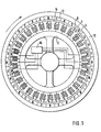
- each electromagnet 4 is arranged on the outer circumference of a stationary functional part 2 in the circumferential direction in a uniform division.
- the electromagnets 4 each have an essentially double T-shaped core 18 in the section shown and have a schematically indicated winding 6 in the central region, the wires of which run perpendicular to the plane of the drawing.
- each electromagnet 4 On the outer circumference, each electromagnet 4 has an electromagnet pole 8 which, depending on the direction of current through the winding 6, is a north pole or a south pole.
- a rotatable functional part 10 Arranged around the stationary functional part 2 is a rotatable functional part 10, which overall has essentially the shape of a hollow cylinder closed on one side in a pot shape and which is fastened axially on the closed side next to the stationary functional part 2 on a shaft, not shown.
- permanent magnets 12 On the inner circumference of the rotatable functional part 10, permanent magnets 12 are attached in a ring-shaped manner with uniform division, namely 32 permanent magnets in the exemplary embodiment shown.
- the permanent magnets 12 offer permanent magnet poles 14 on their inner circumference, specifically in Circumferential direction alternately north poles and south poles.
- the permanent magnets 12 and the permanent magnet poles 14 are each substantially as long in the circumferential direction as the electromagnet poles 8.
- the individual permanent magnets 12 abut each other directly in the circumferential direction and can be glued, for example.
- two permanent magnet poles 14 are provided more than electromagnetic poles 8. Not all electromagnets 4 are switched over at the same time, but with the help of 5 electronic switching devices (cf. following description of FIG. 3) 6 electromagnets 4 each at the same time, namely two diametrically opposed groups of three of electromagnets 4.
- the two groups of three are exactly the same Relative position to permanent magnetic poles 14, while within each group of three the relative position to permanent magnetic poles 14 varies slightly from electromagnetic pole 8 to electromagnetic pole 8.
- An electronic switching device 16 for the 6 electromagnets 4 described is shown schematically. 4 further such electronic switching devices 16 are provided analogously to the switching of the remaining electromagnets 4.
- a Hall probe is attached as a sensor S which detected the change from rotating permanent magnet north pole to permanent magnet south pole and vice versa. This information about the relative position of the stationary functional part 2 and the rotatable functional part 10 is passed on to the respective switching device 16.
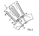
- Each electromagnet 4 has a double T-shaped core 18 in the sectional view shown.
- the core 18 can be formed as a stack of iron lamellae layered perpendicular to the plane of the drawing. Another possibility is to construct the core 18 from iron powder particles embedded as densely as possible in plastic, the core 18 being particularly easy to produce by injection molding. This technique of manufacturing and building cores 18 of electromagnets 4 is considered to be independently inventive.
- each core 18 has an axially extending, undercut groove 20. With the aid of a strip 22 inserted into this groove 20 and provided with threaded bores, each core 18 is screwed from the inside to the stationary functional part 2 by means of screws 24.
- the technique described for the production of the cores 18 and the simple attachment of the cores 18 to the stationary functional part 2 described is possible in particular because the stationary functional part 2 does not rotate, so that the electromagnets 4 are not subjected to centrifugal force.
- Adjacent electromagnets 4 are provided with their feet 26, that is the radially inner leg of the double-T-shaped cross-section, abutting one another in the circumferential direction.
- the foot contact surfaces 28 ensure a magnetic flux path between adjacent electromagnets 4 so that no magnetically conductive back has to be provided radially inside the electromagnets 4 on the stationary functional part 2.
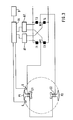
- Fig. 3 shows an electronic switching device in more detail. Of the electric machine, only the stationary functional part 2 is shown with two diametrically opposite electromagnets 4, namely the middle electromagnet 4 from the respective group of three.
- the windings designated here with E1 and E2 are connected in series; however, they could also be connected in parallel.
- the series connection with the windings E1 and E2 is connected to the two center points M1 and M2 of a switching bridge which, in the embodiment shown, is constructed with 4 controllable semiconductor switching elements T1, T2, T3 and T4.
- the switching bridge is connected at one end to the negative pole and at the other end to the positive pole of an operating voltage source.
- the control electrodes of the semiconductor switching elements T1 and T4 which are diagonally opposite in the bridge circuit are connected to the output of a first control circuit A1, while the control electrodes of the remaining semiconductor switching elements T2 and T3 are connected to the output of a second control circuit A2.
- Control connections on the input side of the control circuits A1 and A2 are connected to separate outputs of a control circuit S.
- At least one sensor S is assigned to one of the two functionally related electromagnetic poles P1 and P2, with which the rotational relative position between this electromagnetic pole and the permanent magnetic pole of the rotating functional part is detected. It is assumed in the illustrated embodiment that the permanent magnetic poles are arranged on a ring which rotates around the outside of the electromagnetic poles P 1 and P2. With the help of the sensor when determining a permanent magnet pole changing the windings E1 and E2 switched.
- the control circuit S is acted upon by an output signal from the sensor S and the control circuit S then uses the two control circuits A1 and A2 to switch on two diagonally opposite semiconductor switching elements of the switching bridge in such a way that current flows in either one or the other direction the windings E1 and E2 connected in series flow.
- two sensors S are provided on both sides of the electromagnetic pole P1, the switching of the current direction in the windings E1 and E2 in one direction of rotation of the electrical machine being controlled by one sensor S and in the other direction by the other sensor S. .
- the control circuit S is also connected to a command circuit B, with which control commands such as start / stop, speed and direction of rotation can be entered.
- the control circuit S is preferably a microprocessor which, with a fixed or changeable program as a function of the command signals from the command circuit B and the output signals from the sensors S, transmits its switching signals to the switching bridge via the control circuits A1 and A2 T1 to T4 there.
- the electronic circuit of the individual electromagnets are susceptible to wear and hers t Ellun g saufwend owned sliding contacts are scwie a commutator avoided.
- the electronic control opens up control options that were only possible with great effort in conventional electrical machines, for example, a large usable speed range with high efficiency, control to a specific torque, speed change and the same.
- the electronic control enables a design with a difference between the number of permanent magnetic poles and the number of electromagnetic poles, which results in a safe motor start, a smooth motor run and a uniform network load.
- the permanent magnets are low-maintenance and energy-efficient.
- winding of the electromagnetic functional part of the machine can be carried out according to the single-phase principle, ie the windings of the individual electromagnets are not connected to one another by bulky, so-called winding heads. This results in the possibility of prefabricating the electromagnets as mutually identical components outside the machine and assembling them as components, with all the advantages for replacement and maintenance.
- the electronic control can be designed as required so that each electronic switching device switches only one or more electromagnets in an at least substantially analogous relative position to permanent magnet poles.
- each electronic switching device switches only one or more electromagnets in an at least substantially analogous relative position to permanent magnet poles.
- one can choose electronic switching devices with the switching power that is just right, in particular a small switching power that is favorable in terms of price, cooling and maintenance.
- the arrangement of the electromagnets radially outside of an inner, stationary F unmiesteil and external attachment of the permanent magnets radially inner to a radially, rotatable functional part simplifies the magnetic attachment as a whole, because the electromagnets are not subject to centrifugal force and because the duration magnets are pressed against their mounting surface by centrifugal force.
- the arrangement of the permanent magnets radially outside the air gap causes the so-called active surface of the machine according to the invention, i.e. the area of the radially opposed electromagnetic poles and permanent magnetic poles, to move radially outward because the permanent magnets take up less radial space than the electromagnets . Because the machine's effective surface is moved further radially outwards, there is more space available for the electromagnets. The greater distance between the active surface and the axis of rotation of the machine results in an increase in the active surface and an enlarged lever arm of the magnetic forces to the axis of rotation of the machine.
- the torque is increased by a factor of about 3 compared to conventional electrical machines, with an additional increase in torque of around a factor of 2 due to the lower reaction of the electromagnetic fields to the exciter part of the machine and because of the largely empty space within the electromagnets - measured by weight - 'there is an additional performance increase of about a factor of 2. All of this together is an improvement of around a factor of 12 and thus represents a technical breakthrough in the field of electrical machines.
Landscapes
- Engineering & Computer Science (AREA)
- Power Engineering (AREA)
- Permanent Field Magnets Of Synchronous Machinery (AREA)
- Permanent Magnet Type Synchronous Machine (AREA)
Priority Applications (3)
| Application Number | Priority Date | Filing Date | Title |
|---|---|---|---|
| AT82104526T ATE29351T1 (de) | 1980-11-11 | 1982-05-24 | Rotatorische, elektrische maschine. |
| EP19820104526 EP0094978B2 (fr) | 1982-05-24 | 1982-05-24 | Machine électrique rotative |
| DE8282104526T DE3277166D1 (en) | 1980-11-11 | 1982-05-24 | Rotatable electrical machine |
Applications Claiming Priority (1)
| Application Number | Priority Date | Filing Date | Title |
|---|---|---|---|
| EP19820104526 EP0094978B2 (fr) | 1982-05-24 | 1982-05-24 | Machine électrique rotative |
Publications (3)
| Publication Number | Publication Date |
|---|---|
| EP0094978A1 true EP0094978A1 (fr) | 1983-11-30 |
| EP0094978B1 EP0094978B1 (fr) | 1987-09-02 |
| EP0094978B2 EP0094978B2 (fr) | 1995-11-02 |
Family
ID=8189049
Family Applications (1)
| Application Number | Title | Priority Date | Filing Date |
|---|---|---|---|
| EP19820104526 Expired - Lifetime EP0094978B2 (fr) | 1980-11-11 | 1982-05-24 | Machine électrique rotative |
Country Status (1)
| Country | Link |
|---|---|
| EP (1) | EP0094978B2 (fr) |
Cited By (15)
| Publication number | Priority date | Publication date | Assignee | Title |
|---|---|---|---|---|
| FR2560461A1 (fr) * | 1984-02-29 | 1985-08-30 | Cem Comp Electro Mec | Machine electrodynamique vernier |
| DE3414312A1 (de) * | 1984-04-16 | 1985-10-24 | Magnet-Motor Gesellschaft für magnetmotorische Technik mbH, 8130 Starnberg | Elektrisch gesteuerter elektromotor |
| EP0189652A1 (fr) * | 1984-12-10 | 1986-08-06 | Precise Power Corporation | Moteur synchrone à courant alternatif |
| EP0160868A3 (fr) * | 1984-04-23 | 1987-01-14 | Kabushiki Kaisha Yaskawa Denki Seisakusho | Moteur sans balai |
| DE3802373A1 (de) * | 1988-01-27 | 1988-08-04 | Johann Reiter | Magnetkraftmotor |
| EP0313764A3 (fr) * | 1987-09-02 | 1989-10-18 | PRAN MAGNETTECHNIK (EUROPE) GMBH & CO. KG | Dispositif de conversion d'énergie |
| EP0405258A3 (en) * | 1989-06-24 | 1991-03-20 | Asea Brown Boveri Aktiengesellschaft | Rotary electric machine |
| DE4128627A1 (de) * | 1991-08-26 | 1993-03-04 | Mannesmann Ag | Verfahren zur veraenderung der geschwindigkeit eines fahrzeuges und fahrzeug zur durchfuehrung dieses verfahrens |
| DE4218888A1 (de) * | 1992-06-09 | 1993-12-16 | Barth Hubert Dipl Ing Fh | Elektrische Maschine |
| WO1995000352A1 (fr) * | 1993-06-17 | 1995-01-05 | Hydro-Quebec | Moteur-roue electrique muni d'une bande peripherique |
| DE19511434A1 (de) * | 1995-03-29 | 1996-10-10 | Thomas Dipl Ing Strothmann | Anordnung zur Verbesserung der Betriebseigenschaften von elektrischen, insbesondere hochpoligen Maschinen mit Fremd-, vorzugsweise Permantenterregung |
| WO2005100074A1 (fr) | 2004-04-15 | 2005-10-27 | The Yokohama Rubber Co., Ltd. | Transpondeur utilise dans le systeme de moteur interne a la roue et roue en etant pourvue |
| EP2006980A2 (fr) * | 2002-03-29 | 2008-12-24 | Matra Manufacturing & Services | Moteur électrique doté d'un stator mince et véhicule doté d'un tel moteur |
| US7723888B2 (en) | 2004-05-25 | 2010-05-25 | Marko Petek | Synchronous electromechanical transformer |
| EP2385609A1 (fr) * | 2010-05-05 | 2011-11-09 | Siemens Aktiengesellschaft | Générateur doté d'un stator segmenté |
Citations (9)
| Publication number | Priority date | Publication date | Assignee | Title |
|---|---|---|---|---|
| US1422414A (en) * | 1919-11-06 | 1922-07-11 | Burke Electric Company | Rotor spider |
| US1958753A (en) * | 1932-12-09 | 1934-05-15 | Heintz & Kaufman Ltd | Stationary armature construction |
| DE1033769B (de) * | 1955-11-30 | 1958-07-10 | Allis Chalmers Mfg Co | Rotor fuer dynamoelektrische Maschinen |
| FR2012981A1 (fr) * | 1968-07-15 | 1970-03-27 | Matsushita Electric Industrial Co Ltd | |
| FR2099961A5 (fr) * | 1970-06-26 | 1972-03-17 | Matsushita Electric Industrial Co Ltd | |
| DE2245557A1 (de) * | 1971-09-18 | 1973-03-22 | Victor Company Of Japan | Buerstenloser gleichstrommotor mit hallelementen |
| FR2267650A1 (fr) * | 1974-04-11 | 1975-11-07 | Teldix Gmbh | |
| FR2268377A1 (en) * | 1974-04-17 | 1975-11-14 | Sacobel | DC motor with U-section pole pieces - has thin webs of pole pieces facing rotor and separating magnets |
| EP0018904A1 (fr) * | 1979-04-26 | 1980-11-12 | Crouzet | Moteur à courant continu sans collecteur |
-
1982
- 1982-05-24 EP EP19820104526 patent/EP0094978B2/fr not_active Expired - Lifetime
Patent Citations (9)
| Publication number | Priority date | Publication date | Assignee | Title |
|---|---|---|---|---|
| US1422414A (en) * | 1919-11-06 | 1922-07-11 | Burke Electric Company | Rotor spider |
| US1958753A (en) * | 1932-12-09 | 1934-05-15 | Heintz & Kaufman Ltd | Stationary armature construction |
| DE1033769B (de) * | 1955-11-30 | 1958-07-10 | Allis Chalmers Mfg Co | Rotor fuer dynamoelektrische Maschinen |
| FR2012981A1 (fr) * | 1968-07-15 | 1970-03-27 | Matsushita Electric Industrial Co Ltd | |
| FR2099961A5 (fr) * | 1970-06-26 | 1972-03-17 | Matsushita Electric Industrial Co Ltd | |
| DE2245557A1 (de) * | 1971-09-18 | 1973-03-22 | Victor Company Of Japan | Buerstenloser gleichstrommotor mit hallelementen |
| FR2267650A1 (fr) * | 1974-04-11 | 1975-11-07 | Teldix Gmbh | |
| FR2268377A1 (en) * | 1974-04-17 | 1975-11-14 | Sacobel | DC motor with U-section pole pieces - has thin webs of pole pieces facing rotor and separating magnets |
| EP0018904A1 (fr) * | 1979-04-26 | 1980-11-12 | Crouzet | Moteur à courant continu sans collecteur |
Cited By (24)
| Publication number | Priority date | Publication date | Assignee | Title |
|---|---|---|---|---|
| FR2560461A1 (fr) * | 1984-02-29 | 1985-08-30 | Cem Comp Electro Mec | Machine electrodynamique vernier |
| WO1985004058A1 (fr) * | 1984-02-29 | 1985-09-12 | Cem - Compagnie Electro-Mecanique | Machine electrodynamique vernier |
| EP0155877A1 (fr) * | 1984-02-29 | 1985-09-25 | Alsthom | Machine électrodynamique vernier |
| US4757220A (en) * | 1984-02-29 | 1988-07-12 | Alsthom | Electrodynamic vernier machine |
| DE3414312A1 (de) * | 1984-04-16 | 1985-10-24 | Magnet-Motor Gesellschaft für magnetmotorische Technik mbH, 8130 Starnberg | Elektrisch gesteuerter elektromotor |
| EP0159005A3 (en) * | 1984-04-16 | 1986-10-22 | Magnet-Motor Gmbh | Electrically controlled electromotor |
| EP0454183A1 (fr) * | 1984-04-16 | 1991-10-30 | Magnet-Motor Gesellschaft für magnetmotorische Technik mbH | Moteur électrique rotatif |
| EP0160868A3 (fr) * | 1984-04-23 | 1987-01-14 | Kabushiki Kaisha Yaskawa Denki Seisakusho | Moteur sans balai |
| EP0189652A1 (fr) * | 1984-12-10 | 1986-08-06 | Precise Power Corporation | Moteur synchrone à courant alternatif |
| EP0313764A3 (fr) * | 1987-09-02 | 1989-10-18 | PRAN MAGNETTECHNIK (EUROPE) GMBH & CO. KG | Dispositif de conversion d'énergie |
| DE3802373A1 (de) * | 1988-01-27 | 1988-08-04 | Johann Reiter | Magnetkraftmotor |
| EP0405258A3 (en) * | 1989-06-24 | 1991-03-20 | Asea Brown Boveri Aktiengesellschaft | Rotary electric machine |
| DE4128627A1 (de) * | 1991-08-26 | 1993-03-04 | Mannesmann Ag | Verfahren zur veraenderung der geschwindigkeit eines fahrzeuges und fahrzeug zur durchfuehrung dieses verfahrens |
| DE4218888A1 (de) * | 1992-06-09 | 1993-12-16 | Barth Hubert Dipl Ing Fh | Elektrische Maschine |
| WO1995000352A1 (fr) * | 1993-06-17 | 1995-01-05 | Hydro-Quebec | Moteur-roue electrique muni d'une bande peripherique |
| DE19511434A1 (de) * | 1995-03-29 | 1996-10-10 | Thomas Dipl Ing Strothmann | Anordnung zur Verbesserung der Betriebseigenschaften von elektrischen, insbesondere hochpoligen Maschinen mit Fremd-, vorzugsweise Permantenterregung |
| DE19511434C2 (de) * | 1995-03-29 | 2002-01-17 | Thomas Strothmann | Elektrische Maschine mit reduziertem Rastmoment |
| EP2006980A2 (fr) * | 2002-03-29 | 2008-12-24 | Matra Manufacturing & Services | Moteur électrique doté d'un stator mince et véhicule doté d'un tel moteur |
| WO2005100074A1 (fr) | 2004-04-15 | 2005-10-27 | The Yokohama Rubber Co., Ltd. | Transpondeur utilise dans le systeme de moteur interne a la roue et roue en etant pourvue |
| EP1757480A4 (fr) * | 2004-04-15 | 2012-02-08 | Yokohama Rubber Co Ltd | Transpondeur utilise dans le systeme de moteur interne a la roue et roue en etant pourvue |
| US7723888B2 (en) | 2004-05-25 | 2010-05-25 | Marko Petek | Synchronous electromechanical transformer |
| EP2385609A1 (fr) * | 2010-05-05 | 2011-11-09 | Siemens Aktiengesellschaft | Générateur doté d'un stator segmenté |
| US8710720B2 (en) | 2010-05-05 | 2014-04-29 | Siemens Aktiengesellschaft | Generator with a segmented stator |
| AU2011201557B2 (en) * | 2010-05-05 | 2014-05-29 | Siemens Aktiengesellschaft | Generator with a segmented stator |
Also Published As
| Publication number | Publication date |
|---|---|
| EP0094978B1 (fr) | 1987-09-02 |
| EP0094978B2 (fr) | 1995-11-02 |
Similar Documents
| Publication | Publication Date | Title |
|---|---|---|
| EP0454183B1 (fr) | Moteur électrique rotatif | |
| DE2260069C2 (fr) | ||
| EP0167803B1 (fr) | Moteur à courant continu triphasé sans collecteur | |
| DE3632509C2 (fr) | ||
| EP1110298B1 (fr) | Machine electrique a aimants permanents | |
| DE3128200C2 (de) | Buerstenloser gleichstrommotor | |
| EP0094978B1 (fr) | Machine électrique rotative | |
| WO1989008346A1 (fr) | Machine electrique | |
| DE29816561U1 (de) | Doppelseitiger bürstenloser Gleichstrommotor mit NE-Kern und axialem Magnetfeld des Dauermagnettyps | |
| DE2800886A1 (de) | Gleichstrommotor | |
| DE3122049C2 (fr) | ||
| DE1918500A1 (de) | Impulsbetaetigter elektrischer Stellantrieb | |
| DE3913501A1 (de) | Kommutatorloser, magnetisch gesteuerter elektromotor | |
| DE1488006C3 (de) | Schrittmotor | |
| DE4419780A1 (de) | Ringförmiger Stator für elektrodynamische Drehmaschine | |
| DE2239167C2 (de) | Kollektorloser Gleichstrommotor mit axialem Luftspalt | |
| DE10055080C2 (de) | Elektrische Linearmaschine | |
| DE2913691C2 (de) | Ständer für einen bürstenlosen Elektromotor | |
| EP0216202B2 (fr) | Moteur électrique | |
| DE69512570T2 (de) | Verbesserter Bürstenlosegleichstrommotor mit Dauermagneten | |
| EP3830930B1 (fr) | Machine électrique | |
| DE2349139A1 (de) | Translatorischer elektrischer schrittmotor | |
| DE2332012C2 (fr) | ||
| EP0342606B1 (fr) | Machine électrique | |
| EP0483778B1 (fr) | Moteur électrique rotatif |
Legal Events
| Date | Code | Title | Description |
|---|---|---|---|
| PUAI | Public reference made under article 153(3) epc to a published international application that has entered the european phase |
Free format text: ORIGINAL CODE: 0009012 |
|
| AK | Designated contracting states |
Kind code of ref document: A1 Designated state(s): AT BE CH DE FR GB IT LI |
|
| 17P | Request for examination filed |
Effective date: 19840529 |
|
| ITF | It: translation for a ep patent filed | ||
| GRAA | (expected) grant |
Free format text: ORIGINAL CODE: 0009210 |
|
| AK | Designated contracting states |
Kind code of ref document: B1 Designated state(s): AT BE CH DE FR GB IT LI |
|
| REF | Corresponds to: |
Ref document number: 29351 Country of ref document: AT Date of ref document: 19870915 Kind code of ref document: T |
|
| REF | Corresponds to: |
Ref document number: 3277166 Country of ref document: DE Date of ref document: 19871008 |
|
| ET | Fr: translation filed | ||
| GBT | Gb: translation of ep patent filed (gb section 77(6)(a)/1977) | ||
| PLBI | Opposition filed |
Free format text: ORIGINAL CODE: 0009260 |
|
| 26 | Opposition filed |
Opponent name: SIEMENS AKTIENGESELLSCHAFT, BERLIN UND MUENCHEN Effective date: 19880415 |
|
| PLBI | Opposition filed |
Free format text: ORIGINAL CODE: 0009260 |
|
| 26 | Opposition filed |
Opponent name: EBM ELEKTROBAU MULFINGEN GMBH & CO. Effective date: 19880601 Opponent name: SIEMENS AKTIENGESELLSCHAFT, BERLIN UND MUENCHEN Effective date: 19880415 |
|
| ITTA | It: last paid annual fee | ||
| PUAH | Patent maintained in amended form |
Free format text: ORIGINAL CODE: 0009272 |
|
| STAA | Information on the status of an ep patent application or granted ep patent |
Free format text: STATUS: PATENT MAINTAINED AS AMENDED |
|
| 27A | Patent maintained in amended form |
Effective date: 19951102 |
|
| AK | Designated contracting states |
Kind code of ref document: B2 Designated state(s): AT BE CH DE FR GB IT LI |
|
| REG | Reference to a national code |
Ref country code: CH Ref legal event code: AEN Free format text: AUFRECHTERHALTUNG DES PATENTES IN GEAENDERTER FORM |
|
| ITF | It: translation for a ep patent filed | ||
| ET3 | Fr: translation filed ** decision concerning opposition | ||
| GBTA | Gb: translation of amended ep patent filed (gb section 77(6)(b)/1977) |
Effective date: 19960221 |
|
| PGFP | Annual fee paid to national office [announced via postgrant information from national office to epo] |
Ref country code: GB Payment date: 20000410 Year of fee payment: 19 |
|
| PGFP | Annual fee paid to national office [announced via postgrant information from national office to epo] |
Ref country code: CH Payment date: 20000412 Year of fee payment: 19 |
|
| PGFP | Annual fee paid to national office [announced via postgrant information from national office to epo] |
Ref country code: FR Payment date: 20000418 Year of fee payment: 19 Ref country code: AT Payment date: 20000418 Year of fee payment: 19 |
|
| PGFP | Annual fee paid to national office [announced via postgrant information from national office to epo] |
Ref country code: BE Payment date: 20000428 Year of fee payment: 19 |
|
| PG25 | Lapsed in a contracting state [announced via postgrant information from national office to epo] |
Ref country code: GB Free format text: LAPSE BECAUSE OF NON-PAYMENT OF DUE FEES Effective date: 20010524 Ref country code: AT Free format text: LAPSE BECAUSE OF NON-PAYMENT OF DUE FEES Effective date: 20010524 |
|
| PG25 | Lapsed in a contracting state [announced via postgrant information from national office to epo] |
Ref country code: BE Free format text: LAPSE BECAUSE OF NON-PAYMENT OF DUE FEES Effective date: 20010531 |
|
| PG25 | Lapsed in a contracting state [announced via postgrant information from national office to epo] |
Ref country code: LI Free format text: LAPSE BECAUSE OF NON-PAYMENT OF DUE FEES Effective date: 20010623 Ref country code: CH Free format text: LAPSE BECAUSE OF NON-PAYMENT OF DUE FEES Effective date: 20010623 |
|
| PGFP | Annual fee paid to national office [announced via postgrant information from national office to epo] |
Ref country code: DE Payment date: 20010724 Year of fee payment: 20 |
|
| BERE | Be: lapsed |
Owner name: MAGNET-MOTOR G- FUR MAGNETMOTORISCHE TECHNIK M.B. Effective date: 20010531 |
|
| REG | Reference to a national code |
Ref country code: CH Ref legal event code: PL |
|
| GBPC | Gb: european patent ceased through non-payment of renewal fee |
Effective date: 20010524 |
|
| PG25 | Lapsed in a contracting state [announced via postgrant information from national office to epo] |
Ref country code: FR Free format text: LAPSE BECAUSE OF NON-PAYMENT OF DUE FEES Effective date: 20020131 |
|
| APAH | Appeal reference modified |
Free format text: ORIGINAL CODE: EPIDOSCREFNO |
|
| PLAB | Opposition data, opponent's data or that of the opponent's representative modified |
Free format text: ORIGINAL CODE: 0009299OPPO |