EP0094987A2 - Strömungsregelungseinrichtung für einen Dampferzeuger - Google Patents
Strömungsregelungseinrichtung für einen Dampferzeuger Download PDFInfo
- Publication number
- EP0094987A2 EP0094987A2 EP82112049A EP82112049A EP0094987A2 EP 0094987 A2 EP0094987 A2 EP 0094987A2 EP 82112049 A EP82112049 A EP 82112049A EP 82112049 A EP82112049 A EP 82112049A EP 0094987 A2 EP0094987 A2 EP 0094987A2
- Authority
- EP
- European Patent Office
- Prior art keywords
- diffuser
- flow
- channels
- inlet nozzle
- nozzle
- Prior art date
- Legal status (The legal status is an assumption and is not a legal conclusion. Google has not performed a legal analysis and makes no representation as to the accuracy of the status listed.)
- Withdrawn
Links
Images


Classifications
-
- F—MECHANICAL ENGINEERING; LIGHTING; HEATING; WEAPONS; BLASTING
- F22—STEAM GENERATION
- F22D—PREHEATING, OR ACCUMULATING PREHEATED, FEED-WATER FOR STEAM GENERATION; FEED-WATER SUPPLY FOR STEAM GENERATION; CONTROLLING WATER LEVEL FOR STEAM GENERATION; AUXILIARY DEVICES FOR PROMOTING WATER CIRCULATION WITHIN STEAM BOILERS
- F22D5/00—Controlling water feed or water level; Automatic water feeding or water-level regulators
- F22D5/04—Controlling water feed or water level; Automatic water feeding or water-level regulators with pivoting buckets
-
- F—MECHANICAL ENGINEERING; LIGHTING; HEATING; WEAPONS; BLASTING
- F28—HEAT EXCHANGE IN GENERAL
- F28F—DETAILS OF HEAT-EXCHANGE AND HEAT-TRANSFER APPARATUS, OF GENERAL APPLICATION
- F28F9/00—Casings; Header boxes; Auxiliary supports for elements; Auxiliary members within casings
- F28F9/02—Header boxes; End plates
- F28F9/026—Header boxes; End plates with static flow control means, e.g. with means for uniformly distributing heat exchange media into conduits
- F28F9/0265—Header boxes; End plates with static flow control means, e.g. with means for uniformly distributing heat exchange media into conduits by using guiding means or impingement means inside the header box
- F28F9/0268—Header boxes; End plates with static flow control means, e.g. with means for uniformly distributing heat exchange media into conduits by using guiding means or impingement means inside the header box in the form of multiple deflectors for channeling the heat exchange medium
-
- F—MECHANICAL ENGINEERING; LIGHTING; HEATING; WEAPONS; BLASTING
- F22—STEAM GENERATION
- F22B—METHODS OF STEAM GENERATION; STEAM BOILERS
- F22B37/00—Component parts or details of steam boilers
- F22B37/02—Component parts or details of steam boilers applicable to more than one kind or type of steam boiler
- F22B37/22—Drums; Headers; Accessories therefor
- F22B37/228—Headers for distributing feedwater into steam generator vessels; Accessories therefor
Definitions
- the invention relates to heat exchangers of the tubular type, such as, for instance, feedwater preheaters, condensers and steam generators.
- a problem involved with heat exchangers of this type arises due to the fact that the tubes adopt severe oscillations caused by turbulence and instability of the flow of liquid around the tubes. At times, the oscillations are so intense that the tube material is rapidly fatigued, a situation which often arises with condensers, for instance. It may even happen that the tube "beats" within a clearing between the tube and tube support plates provided with apertures through which the tubes extend, resulting in an abrasion of the tube material at contact surfaces between the tube and the support plate. The wear may proceed to such a degree that severe leaks arise. Evidently, such leakages are inpermissible in nuclear reactor plants.
- the principal object of the present invention is to provide a feasible means for solving this problem and particularly so in steam generator plants in which tube wear has already been observed or in new plants in which such wear may be expected.
- the present invention resides in a device for providing a substantially uniform and vortex-free inflow and distribution of feedwater to a heat exchanger constituting a steam generator and comprising a plurality of tubes constituting a tube bundle (78) for a primary fluid to heat said feedwater as the secondary fluid, and a generator shell (5) enclosing the tube bundle and having an inlet nozzle (4) and an outlet nozzle for said feedwater, said inlet nozzle having therein a diffuser structure (21), characterized by a number of diffuser channels (22, 30, 31, 32) adapted to restrict an outflow of water from the generator shell through said inlet nozzle (4) during a break in a feedwater pipe connected to said inlet nozzle and arranged within the inlet nozzle and by baffle means (71-76, 80, 91, 97) associated with said diffuser structure to deflect the feedwater flow in a radial direction about said inlet nozzle and arranged closely adjacent the inlet nozzle (4) between the downstream ends of the diffuser structure
- a prior art steam generator having a shell to which hot pressurized water is supplied in a primary fluid circuit from a . heat source, a nuclear reactor, for instance, through a primary water inlet nozzle 1 of the steam generator.
- the water flows upwardly through a plurality of closely packed tubes having a relatively small diameter, 20 mm, for instance.
- the tubes bend downwardly within the right-hand half of the generator shell.
- Said last-mentioned tube portions within which the water flows downwardly are represented by five tubes 2.
- the primary water returns through the outlet nozzle 3 to the nuclear reactor to be reheated.
- the water of the secondary circuit having about half the pressure of the primary circuit pressure, is supplied to the steam generator through a secondary water inlet nozzle 4 welded to the rigid shell 5 of the generator.
- Feedwater from a feedwater supply pump of the secondary circuit is considerably colder than the water vaporization temperature corresponding to the pressure prevailing in the major part of the secondary circuit of the generator.
- the cold feedwater is utilized for bringing about a drastic cooling of the primary water flowing through the lower right-hand tube section of the generator, said section thus functioning like an economizer.
- the hot primary water causes a vaporization of the secondary circuit water.
- the feedwater enters the space between the tubes of the tube bundle, across the tubes and between the tube support plates 6 and 7. A portion of the flow bends downwardly and takes a zigzag course over the support plates 8-11 through orifices at their respective ends. A second portion of the flow flows upwardly along the support plates 12-16.
- FIG. 2 shows more in detail a prior art steam generator inlet nozzle 4 with pertaining flow damping members in a horizontal section.
- the secondary water supply pipe 20 is connected to the inlet nozzle by welding.
- a flow restricting member 21, below called diverging nozzle unit is arranged close to the feedwater pipe within the inlet nozzle 4.
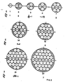
- the diverging nozzle unit 21 consists of a number, in the present case 4, of diverging nozzle ducts 22 having a smallest orifice 23 after, a smoothly rounded inlet surface 24.
- two circular baffle plates 25 and 26 are arranged in front of the inlet orifice at some small distances therefrom. In a convenient manner, for instance by stays 27, 28, said plates are secured to the shell and provided with a number of apertures 29, to distribute the water flow.
- the water velocity after the nozzle unit 21 with its water velocity of about 30 m/s in the smallest section of the nozzles is decreased to such a degree that the feedwater flow, when entering into the tube bundle, has obtained such a low velocity that the tubes are not exposed to forced oscillations of an amplitude to endanger the mechanical strength of the tubes by wearing or fatigue.
- the inflow velocity of the feedwater should be brought down to about 2.5 m/s or below to obtain a sufficiently low Strouhals number.
- the following calculation may be made.
- the number of diverging nozzles should be comparatively large and the outlets of the nozzles cover an area which constitutes as large a part of the inlet area as possible.
- the nozzle angle must not be larger than 2 x 4° to obtain a stable and uniform flow through the diffuser portion of the nozzle, implying that the diameter increase after the smallest cross section of the nozzle should not be larger than 2 x 7% per length unit.
- the largest allowable area with respect to the throttling of the flow for a pipe burst being called A min and the number of nozzles z, the diameter of the nozzle at the throat will be
- the number of nozzles should preferably be at least 14 to bring down the required length of the nozzle unit to below the diameter of the unit. It is of interest to reach a length which is as short as possible and a coverage which is as high as possible, the number of nozzles being as low as possible. It will be seen from the table that the improvement of the coverage is comparatively small from 3 diverging nozzles up to 37 nozzles, and may for some purposes not be considered as satisfactory, only about 3/4 of the inlet area being utilized, the diffuser length, however, decreasing from about 1.5 to 0.5 times the diameter of the nozzle unit.
- the number of diverging nozzle channels of circular cross section should, to obtain a length of the diverging portion of each channel of the unit which is shorter than the diameter of the supply pipe, have a number of at least 14, although 7 diverging nozzles obtain a more than 10% larger coverage, however at the expense of a considerably much longer length.
- a further improvement is obtained by arranging a number of diffuser rings constituting vanes for guiding the flow and applying to it a radial velocity with a selected velocity component in the direction of flow toward the tube bundle as more closely described below.
- a radial distribution is to be effected in the water flow from the nozzles, in such a way that more water is conducted in a horizontal direction than in a vertical one in order to obtain an acceptably uniform velocity distribution to each tube row, avoiding local high velocities.
- this is obtained by arranging separate diffuser nozzles having the shape of segments of a circle and dimensioned for selected water flows to be guided with a radial deflection in the direction of the outlet of the nozzle unit.
- an embodiment according to the invention comprises one single, centrally arranged flow restricting nozzle in combination with a set of ring-shaped diffusers arranged downstream, the nozzle to deflect the flow into a substantially radial direction.
- the flows are distributed in such a manner that a larger part of the flow is being distributed in a horizontal direction than in a vertical direction.
- Fig. 4 shows a horizontal cross section of a steam generator inlet nozzle 4 having a diverging nozzle unit 21 which, in accordance with the invention, comprises 37 diverging nozzle ducts 22.
- This embodiment is particularly suited for the secondary water inlet of a steam generator in which the height of the tube bundle is about as large as the width thereof.
- a cross-shaped plate member consisting of two plates 71, 72, which extend as two mutually crossing guide plates from the diverging nozzle unit in the direction toward the tube bundle.
- edges of the plates 71, 72 extending into the space within the generator vessel are cut at about 45° as shown, carrying at their top a member 73 having a number of substantially axial or somewhat diverging orifices 77.
- the edges 75 of the plates 71 and 72 facing the nozzle unit should be located at a distance from the nozzle unit.
- the cross-shaped plate member 71, 72 carries a number of diffuser vane rings 76 located at distances from each other covering the flow cross section.
- the diffuser rings 76 have a vane-shaped cross section and are directed to diverge the water flow, entering the generator substantially in a radial direction, thereby retarding the flow velocity before the water reaches the tubes 78 of the tube bundle.
- the rings shown in the Figure in a number of 6, may consist of four portions, each secured at radial distances from each other between the plates 71 and 72.
- the rings 76 are arranged with equal pitches, the vane shape being selected with inflow and outflow angles to deflect the flow and obtain a uniform, substantially peripheral velocity having a selected component in the axial direction after the rings and to obtain favorable inflow velocities to the tube bundle.
- the coverage that is the ratio between the sum of the downstream areas of the diverging nozzles of the nozzle unit 21 and the inlet duct area may, in some cases, not be considered to be satisfactory even for a high number of nozzles having circular downstream apertures, in that only 3/4 of the secondary fluid pipe is being utilized.
- the diverging nozzle channels of the nozzle unit 21 having circular cross section over their full length are replaced by nozzle sections which, at the exit end of the unit, together form substantially annular sections.
- the diffuser channels should be formed by walls sloped with respect to the flow direction by not more than 7°.
- the edge radius should be of the same order of size as the radius of the smallest section. Under these circumstances, the minimal length, as compared with circular nozzle cross sections, must be increased by a factor of 2 to obtain an optimal flow without cavitations at the edges.
- a diverging nozzle unit 21 comprising 21 diverging nozzles is, consequently, considered as an optimal solution and is illustrated by Fig. 6, in which the nozzle apertures of the diverging nozzle unit is seen in the direction from the steam generator.
- the nozzle unit comprises a central circular diverging nozzle 30, around which two circular rows of 8 diverging nozzles 31 and 12 diverging nozzles 32, respectively, are arranged, all with a circular smallest section 33 and with annular sector-shaped outlets.
- the outlets are more or less rectangular with radial side walls 34 and 35, respectively, and part-circular walls 36 and 37, respectively, extending along circles about the center of the central diverging nozzle.
- the edges of the annulus sectors are rounded, as mentioned above with about the same radius as the inlet radius.
- the walls of adjacent diverging nozzles at the nozzle outlets are bevelled to terminate in a sharp edge, e.g. as illustrated by Figs. 7, 8 and 9, showing the edges 40, 50 and 60 of walls along lines A, B and C, respectively, of Fig. 6.
- the diverging nozzle unit consists of a substantially cylindrical member of a material suited for the purpose.
- the feedwater is to be distributed over the water inlet area of the tube bundle in such a manner that a considerably larger quantity of water is distributed horizontally than vertically.
- Means for providing such distribution of the feedwater are illustrated by Figs. 10 to 15, showing an arrangement by which selected different water quantities are guided in different directions to fulfill this purpose.
- the diverging nozzles guide the flow within the separate annulus sectors into the space around the mouths of the nozzles, which are dimensioned to obtain an optimally directed inflow.
- Fig. 10 is a horizontal section and Fig. 11 a vertical section through the diverging nozzle unit and the tube bundle.
- the cross section of the diverging nozzle unit 21 at a location where the diffuser portion of the unit is terminated is to be seen in Fig. 11.
- the annular sector shaped downstream ends of the diverging nozzles 22 are extended peripherally up to a baffle plate 81.
- the flow quantities of the upper and lower nozzle outlets should be smaller than the quantities of the side nozzles, the flow of which is to be distributed far into the corners of the tube bundle enclosure.
- the supply of water in the vertical section should have a more axial direction than in the horizontal section, which is provided for by arranging the mouths of the nozzle outlets as illustrated by Figs. 12 through 15, representing views in the axial direction of the inlet nozzle 4 of sections A, D, E and F, respectively.
- the flow deviating portion of the outlet channels from the respective diverging nozzles 22 is terminated by the baffle plate 81, directing the water flow radially and horizontally as regards the channels 1, 4, 5 and 8 of Fig. 13, while the flow from the central diverging nozzle and channels 2, 3, 6 and 7 are guided into a more axial direction, as will be seen from Fig. 11.
- the substantially radial walls of the annulus sector-shaped channels in the flow deviating portion of the channels are formed to distribute the flows emerging from the diverging nozzles in a direction toward the external portions of the tube bundle, as will be seen from Figs. 13, 14 and 15, respectively.
- the deflection portion 80 is attached by welding to the diverging nozzle unit 21, so as to be attached to the inlet nozzle 4 as a unit by welding seams 79, arranged so as to keep the diverging nozzle unit 22 in place in case of a pipe burst.
- Fig. 16 illustrates a further embodiment, in which pipe burst flow restriction is provided for by the use of one single nozzle 90 having, adjacent the smallest cross section area thereof, a plurality of annular diffuser vanes 91, within which the high velocity prevailing in the smallest cross section is reduced to acceptable values at the cylindrically shaped diffuser outlet openings 92 of the diffuser unit 21.
- the unit 21 is mounted within a tubular inlet stud 93.
- a flow rectifying plate member 94 having straight channels of square cross section is arranged ahead of the nozzle in the direction of flow.
- a number (such as 5 to 7) of diffuser rings 91 are arranged, as shown in Fig. 16, which are shaped so as to form diffuser channels.
- the axial and radial pitches of the diffuser rings 91 are selected so as to obtain substantially uniform flow velocities where the water enters the tube bundle 78.
- the annular diffuser channels 92 are subdivided by substantially radial guide walls 97, arranged so as to guide the flow outwardly to the external horizontal parts of the tube bundle and smaller flow quantities to the spaces 96 above and below the inlet nozzle.
- Said guide walls 97 support the diffuser rings 91 and hold together the diffuser unit 21.
- the diffuser ring may consist of machined rings 91, to which the guide walls 97 are attached by welding to the convex and concave, respectively, surfaces of the rings.
Landscapes
- Engineering & Computer Science (AREA)
- Physics & Mathematics (AREA)
- Thermal Sciences (AREA)
- Mechanical Engineering (AREA)
- General Engineering & Computer Science (AREA)
- Jet Pumps And Other Pumps (AREA)
- Structure Of Emergency Protection For Nuclear Reactors (AREA)
- Control Of Turbines (AREA)
- Turbine Rotor Nozzle Sealing (AREA)
Priority Applications (1)
| Application Number | Priority Date | Filing Date | Title |
|---|---|---|---|
| SE8302405A SE8302405L (en) | 1982-04-28 | 1983-04-28 | Flow control device for heat exchanger - comprises diffuser structure within inlet nozzle of shell and associated baffle |
Applications Claiming Priority (2)
| Application Number | Priority Date | Filing Date | Title |
|---|---|---|---|
| SE8202676 | 1982-04-28 | ||
| SE8202676A SE430715B (sv) | 1982-04-28 | 1982-04-28 | Sett och inforande av sekundervatten genom ett inlopp till ett anggeneratorkerl |
Publications (2)
| Publication Number | Publication Date |
|---|---|
| EP0094987A2 true EP0094987A2 (de) | 1983-11-30 |
| EP0094987A3 EP0094987A3 (de) | 1984-10-10 |
Family
ID=20346670
Family Applications (1)
| Application Number | Title | Priority Date | Filing Date |
|---|---|---|---|
| EP82112049A Withdrawn EP0094987A3 (de) | 1982-04-28 | 1982-12-28 | Strömungsregelungseinrichtung für einen Dampferzeuger |
Country Status (5)
| Country | Link |
|---|---|
| US (1) | US4573526A (de) |
| EP (1) | EP0094987A3 (de) |
| KR (1) | KR840004489A (de) |
| ES (1) | ES521751A0 (de) |
| SE (1) | SE430715B (de) |
Cited By (5)
| Publication number | Priority date | Publication date | Assignee | Title |
|---|---|---|---|---|
| WO1998003826A1 (en) * | 1996-07-19 | 1998-01-29 | American Standard Inc. | Evaporator refrigerant distributor |
| US5868163A (en) * | 1996-01-25 | 1999-02-09 | Mcdonald; Christopher William | Flow restriction device |
| US7529823B2 (en) | 2003-03-27 | 2009-05-05 | Microsoft Corporation | Notifications for shared resources |
| EP3364121A1 (de) * | 2017-02-16 | 2018-08-22 | HS Marston Aerospace Limited | Strömungsführung für wärmetauscher |
| US11226158B2 (en) * | 2019-04-01 | 2022-01-18 | Hamilton Sundstrand Corporation | Heat exchanger fractal splitter |
Families Citing this family (16)
| Publication number | Priority date | Publication date | Assignee | Title |
|---|---|---|---|---|
| JP2952102B2 (ja) * | 1991-04-05 | 1999-09-20 | ウエスチングハウス・エレクトリック・コーポレイション | 熱交換器 |
| US5388398A (en) * | 1993-06-07 | 1995-02-14 | Avco Corporation | Recuperator for gas turbine engine |
| US5752566A (en) * | 1997-01-16 | 1998-05-19 | Ford Motor Company | High capacity condenser |
| US5755113A (en) * | 1997-07-03 | 1998-05-26 | Ford Motor Company | Heat exchanger with receiver dryer |
| US20040039407A1 (en) * | 2002-04-29 | 2004-02-26 | Steven Schraga | Lancet device |
| US20070028647A1 (en) * | 2005-08-04 | 2007-02-08 | York International | Condenser inlet diffuser |
| US9697919B2 (en) | 2010-12-29 | 2017-07-04 | Westinghouse Electric Company, Llc | Anti-vibration tube support plate arrangement for steam generators |
| GB2504547A (en) * | 2012-08-03 | 2014-02-05 | Tube Tech Int Ltd | Parallel tube heat exchanger having a baffle to modify direction and flow rate of an incoming process fluid |
| US20140116360A1 (en) * | 2012-10-31 | 2014-05-01 | Westinghouse Electric Company Llc | Method and apparatus for securing tubes in a steam generator against vibration |
| CN103187113B (zh) * | 2013-01-18 | 2017-03-01 | 上海核工程研究设计院 | 一种核电站蒸汽发生器蒸汽限流装置 |
| CN103174705A (zh) * | 2013-03-18 | 2013-06-26 | 中国兵器工业集团第七0研究所 | 一种流线型导流板结构 |
| JP6787647B2 (ja) | 2014-09-08 | 2020-11-18 | 三菱重工サーマルシステムズ株式会社 | ターボ冷凍機 |
| CN104329325A (zh) * | 2014-10-22 | 2015-02-04 | 无锡杰尔压缩机有限公司 | 一种用于风机进气的稳流装置 |
| US10782071B2 (en) * | 2017-03-28 | 2020-09-22 | General Electric Company | Tubular array heat exchanger |
| CN112923776B (zh) * | 2021-01-16 | 2022-12-09 | 西安交通大学 | 一种管壳式换热器用弓形折流板 |
| EP4621338A1 (de) * | 2024-03-18 | 2025-09-24 | Linde GmbH | Flüssigkeitseinlasssystem, vorrichtung und verfahren zur flüssigkeitsversorgung |
Family Cites Families (11)
| Publication number | Priority date | Publication date | Assignee | Title |
|---|---|---|---|---|
| CA647847A (en) * | 1962-09-04 | N. Hinde James | Condensers | |
| DE322789C (de) * | 1918-01-27 | 1920-07-08 | Norddeutsche Kuehlerfabrik G M | Wasserverteiler fuer Kuehler von Fahrzeugmotoren |
| US1987116A (en) * | 1933-09-08 | 1935-01-08 | Charles H Leach | Heat exchange apparatus |
| US2753932A (en) * | 1951-07-30 | 1956-07-10 | Blaw Knox Co | Liquid distributing bell for vertical tubes |
| DE1501620A1 (de) * | 1964-04-09 | 1969-06-26 | Grenobloise Etude Appl | Verbesserungen aus Waermeaustauschern |
| US3519024A (en) * | 1966-01-06 | 1970-07-07 | Gen Electric | Device for the prepatterned control of flow distribution in fluid flow experiencing a change in area and/or direction |
| SU203708A1 (ru) * | 1966-03-12 | 1967-10-09 | Ф. А. Фролов, И. А. Ганичев , Н. И. Молодцов Центральный научно исследовательский дизельный институт | Кожухотрубчатый теплообменник |
| DE2128162A1 (de) * | 1971-06-07 | 1972-12-28 | L. & C. Steinmüller GmbH, 5270 Gummersbach | Vorrichtung zum gleichmäßigen Umlenken und Verteilen von Mehrphasenströmen |
| US3706301A (en) * | 1971-07-13 | 1972-12-19 | Combustion Eng | Integral economizer for u-tube generator |
| DE2346411A1 (de) * | 1973-09-14 | 1975-04-03 | Kraftwerk Union Ag | Dampferzeuger |
| JPS5819037B2 (ja) * | 1977-09-30 | 1983-04-15 | 三菱重工業株式会社 | 柱状物体後流のカルマン渦の防止方法 |
-
1982
- 1982-04-28 SE SE8202676A patent/SE430715B/sv not_active IP Right Cessation
- 1982-12-28 EP EP82112049A patent/EP0094987A3/de not_active Withdrawn
-
1983
- 1983-03-15 US US06/475,587 patent/US4573526A/en not_active Expired - Lifetime
- 1983-04-14 KR KR1019830001575A patent/KR840004489A/ko not_active Withdrawn
- 1983-04-22 ES ES521751A patent/ES521751A0/es active Granted
Cited By (5)
| Publication number | Priority date | Publication date | Assignee | Title |
|---|---|---|---|---|
| US5868163A (en) * | 1996-01-25 | 1999-02-09 | Mcdonald; Christopher William | Flow restriction device |
| WO1998003826A1 (en) * | 1996-07-19 | 1998-01-29 | American Standard Inc. | Evaporator refrigerant distributor |
| US7529823B2 (en) | 2003-03-27 | 2009-05-05 | Microsoft Corporation | Notifications for shared resources |
| EP3364121A1 (de) * | 2017-02-16 | 2018-08-22 | HS Marston Aerospace Limited | Strömungsführung für wärmetauscher |
| US11226158B2 (en) * | 2019-04-01 | 2022-01-18 | Hamilton Sundstrand Corporation | Heat exchanger fractal splitter |
Also Published As
| Publication number | Publication date |
|---|---|
| SE430715B (sv) | 1983-12-05 |
| KR840004489A (ko) | 1984-10-15 |
| ES8502243A1 (es) | 1984-12-16 |
| ES521751A0 (es) | 1984-12-16 |
| EP0094987A3 (de) | 1984-10-10 |
| SE8202676L (sv) | 1983-10-29 |
| US4573526A (en) | 1986-03-04 |
Similar Documents
| Publication | Publication Date | Title |
|---|---|---|
| EP0094987A2 (de) | Strömungsregelungseinrichtung für einen Dampferzeuger | |
| US4629481A (en) | Low pressure drop modular centrifugal moisture separator | |
| US7245689B2 (en) | Nuclear reactor internal structure | |
| US8002866B2 (en) | Steam-water separator | |
| KR100380920B1 (ko) | 열교환기의 관지지구조 | |
| US20240410566A1 (en) | Helical Baffle for Once-Through Steam Generator | |
| FI127060B (en) | A steam separator and a boiling water reactor with steam separator | |
| EP0183049B1 (de) | Strömungsverteilerlochplatte | |
| JP2952102B2 (ja) | 熱交換器 | |
| US4318368A (en) | Orificing of steam separators for uniform flow distribution in riser area of steam generators | |
| US6173680B1 (en) | Steam generator comprising an improved feedwater supply device | |
| EP0062344A2 (de) | Abhitzekessel und Dampfüberhitzersystem | |
| KR101940356B1 (ko) | 막힘 방지형 증기 발생기 튜브 번들 | |
| WO2021102885A1 (zh) | 压水堆核电站立式蒸汽发生器及其松动部件捕集装置 | |
| JPH08323126A (ja) | スプレータワー | |
| US4736713A (en) | Foraminous or perforated flow distribution plate | |
| US3895674A (en) | Inlet flow distributor for a heat exchanger | |
| JPS6116882B2 (de) | ||
| CA1085244A (en) | Vapor generating unit blowdown arrangement | |
| US4057033A (en) | Industrial technique | |
| US5234161A (en) | Counterflow spray nozzle | |
| USRE30033E (en) | Vertical firetube waste heat boiler | |
| US5329886A (en) | Steam generator | |
| US4158603A (en) | Blow-off device for limiting excess pressure in nuclear power plants, especially in boiling-water nuclear power plants | |
| US5213065A (en) | Steam generator feedwater distribution system |
Legal Events
| Date | Code | Title | Description |
|---|---|---|---|
| PUAI | Public reference made under article 153(3) epc to a published international application that has entered the european phase |
Free format text: ORIGINAL CODE: 0009012 |
|
| AK | Designated contracting states |
Designated state(s): BE CH DE FR IT LI |
|
| PUAL | Search report despatched |
Free format text: ORIGINAL CODE: 0009013 |
|
| AK | Designated contracting states |
Designated state(s): BE CH DE FR IT LI |
|
| 17P | Request for examination filed |
Effective date: 19850320 |
|
| STAA | Information on the status of an ep patent application or granted ep patent |
Free format text: STATUS: THE APPLICATION IS DEEMED TO BE WITHDRAWN |
|
| 18D | Application deemed to be withdrawn |
Effective date: 19861007 |
|
| RIN1 | Information on inventor provided before grant (corrected) |
Inventor name: JUNG, INGVAR |