EP0095037A2 - Dispositif de surveillance du lubrifiant dans un compresseur à piston - Google Patents
Dispositif de surveillance du lubrifiant dans un compresseur à piston Download PDFInfo
- Publication number
- EP0095037A2 EP0095037A2 EP83103698A EP83103698A EP0095037A2 EP 0095037 A2 EP0095037 A2 EP 0095037A2 EP 83103698 A EP83103698 A EP 83103698A EP 83103698 A EP83103698 A EP 83103698A EP 0095037 A2 EP0095037 A2 EP 0095037A2
- Authority
- EP
- European Patent Office
- Prior art keywords
- electrode
- piston rod
- capacitor
- arrangement according
- lubricant
- Prior art date
- Legal status (The legal status is an assumption and is not a legal conclusion. Google has not performed a legal analysis and makes no representation as to the accuracy of the status listed.)
- Granted
Links
Images




Classifications
-
- F—MECHANICAL ENGINEERING; LIGHTING; HEATING; WEAPONS; BLASTING
- F04—POSITIVE - DISPLACEMENT MACHINES FOR LIQUIDS; PUMPS FOR LIQUIDS OR ELASTIC FLUIDS
- F04B—POSITIVE-DISPLACEMENT MACHINES FOR LIQUIDS; PUMPS
- F04B39/00—Component parts, details, or accessories, of pumps or pumping systems specially adapted for elastic fluids, not otherwise provided for in, or of interest apart from, groups F04B25/00 - F04B37/00
- F04B39/02—Lubrication
- F04B39/0207—Lubrication with lubrication control systems
-
- F—MECHANICAL ENGINEERING; LIGHTING; HEATING; WEAPONS; BLASTING
- F04—POSITIVE - DISPLACEMENT MACHINES FOR LIQUIDS; PUMPS FOR LIQUIDS OR ELASTIC FLUIDS
- F04B—POSITIVE-DISPLACEMENT MACHINES FOR LIQUIDS; PUMPS
- F04B49/00—Control, e.g. of pump delivery, or pump pressure of, or safety measures for, machines, pumps, or pumping installations, not otherwise provided for, or of interest apart from, groups F04B1/00 - F04B47/00
- F04B49/10—Other safety measures
-
- Y—GENERAL TAGGING OF NEW TECHNOLOGICAL DEVELOPMENTS; GENERAL TAGGING OF CROSS-SECTIONAL TECHNOLOGIES SPANNING OVER SEVERAL SECTIONS OF THE IPC; TECHNICAL SUBJECTS COVERED BY FORMER USPC CROSS-REFERENCE ART COLLECTIONS [XRACs] AND DIGESTS
- Y10—TECHNICAL SUBJECTS COVERED BY FORMER USPC
- Y10S—TECHNICAL SUBJECTS COVERED BY FORMER USPC CROSS-REFERENCE ART COLLECTIONS [XRACs] AND DIGESTS
- Y10S277/00—Seal for a joint or juncture
- Y10S277/919—Seal including electrical feature
Definitions
- the invention relates to a lubricant monitoring arrangement on a piston compressor, in particular for compressing oxygen.
- a lantern-like housing part with observation openings is provided between the crankcase and the housing containing the cylinders.
- a partition is provided which also has lubricant rings for the piston rod.
- a seal is provided which surrounds the piston rod and prevents the escape of oxygen from the cylinder into the lantern chamber.
- a ring is clamped onto the piston rod, which prevents the wafer-thin film of lubricant from spreading Forms crankcase on the piston rod, reaches the area of the seal on the cylinder housing.
- the wafer-thin lubricant film on the piston rod does not pose any risk of fire, since the lubricant film does not move relative to the piston rod and cannot exceed the ring attached to it. If, however, the lubricant scraper rings are no longer intact or worn, lubricant can be dragged from the crankcase in such an amount that the lubricant gradually exceeds the clamped ring and then reaches the seal on the cylinder housing, where there is contact between oxygen and lubricant Fire could arise.
- the invention has for its object to provide a lubricant monitoring arrangement that detects any penetration of large amounts of lubricant on the piston rod and can then turn off the piston compressor and / or give an alarm.
- this object is achieved in that on the piston rod between an oil wiper pack and a seal which the piston rod penetrates at their penetration closing level surrounding the compressor cylinder, at least one liquid lubricant
- the absorbent body and in the region of an electrode of a measurement capacitor prior g are e-view, wherein the absorbent body is used as the dielectric of the measuring capacitor.
- the dielectric constant of the absorbent body changes, which is reflected in a change in the signals from the measuring capacitor. This signal change can then be used to switch off the compressor and / or to trigger an alarm. It is therefore unnecessary to determine the effectiveness of the oil scraper pack from outside or inside any protective walls by observation or possibly to set up protective walls and the like in the area of the compressor.
- the electrode of the measuring capacitor is connected to a further electrode which, together with an electrode which is arranged at rest while leaving an air gap free, forms a coupling capacitor to which a capacitance measuring device is connected. This avoids connecting the connections of the non-moving capacitance measuring device to the moving electrode or moving this measuring device with the piston rod.
- a second electrode of the same dimension and shape as the electrode of the measuring capacitor is attached to the piston rod between the lubricant-absorbing body and the seal provided that, together with an air space, which is located as a dielectric between the second electrode and the piston rod, forms a comparison capacitor.
- the comparative capacitor and the measuring capacitor are therefore subject to approximately the same heat influences that occur during the Operation of the compressor can occur. Since both the capacitance of the measuring capacitor and that of the comparative capacitor are recorded with each stroke of the piston rod, changes in capacitance caused by the effects of heat are thus compensated for.
- the piston compressor has a cylinder housing 1 and a crankcase 2, which is connected to the cylinder housing 1 via a lantern-like housing part 3.
- a piston rod 5 From the crankcase 2 extends through the lantern-like Housing 3 is a piston rod 5, which is extended into the cylinder housing 1 and carries a piston at its upper end in FIG. 1 in a manner not shown.
- a seal 6 of a known type is provided at the point where the piston rod 5 penetrates the cylinder housing 1, a seal 6 of a known type is provided.
- a piston rod guide bearing 8 of a known type with three oil scraper rings 9 is provided in a partition 7 between the crankcase 2 and the lantern-like housing part 3.
- the oil scraper rings 9 ensure that lubricating oil from the crankcase 2 can at most spread as a wafer-thin film on the vertical piston rod 5, at most up to an oil trapping device 10 which is clamped on the piston rod 5.
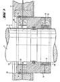
- a lubricating oil monitoring device 11 is arranged on the upper end of the guide bearing 8 in FIG. 1, to which parts of the oil trapping device 10 also belong and which is shown in more detail in FIG. 2.
- the oil trap 10 is composed of a ring 12 made of cotton or felt, an axially split sleeve 13 made of insulating material, for example Delrin (registered trademark) and an O-ring 14.
- the two-part sleeve 13 is held on the piston rod 5 by screws, not shown.
- the latter is provided with a weak constriction 16 which is filled by the sleeve 13 and against which the O-ring 14 also bears.
- the metal covering 18 also expediently consists of an electroplated copper layer.
- the annular coating 18 forms an electrode of a coupling capacitor CK, the second electrode of which is formed by an annular metal coating 19 which e.g. in the form of an electroplated copper layer on the inner peripheral surface of an annular insulating body 20.
- the insulating body 20 can also consist of Delrin and is contained in an annular electrode holder 21 which is fastened on the housing of the piston rod guide bearing 8.
- the electrode 19 of the coupling capacitor is thus stationary and arranged relative to the electrode 18 such that it is opposite the piston rod of the electrode 19 at bottom dead center (UTP). This position corresponds to the position shown in FIG. 2.
- the electrode 19 is connected to a capacitance measuring device in a manner not shown here.
- the measuring device can be connected to an alarm transmitter or can directly switch off the drive of the compressor.
- FIG. 3 shows a further developed embodiment in which any influence of temperature on the capacitance measurement is compensated for.
- a comparative capacitor CV is provided in the oil trap 10 '.
- the comparative capacitor CV consists of an air space 22, the dimensions and shape of which are the same as the dimensions or the shape of the space of the measuring capacitor CM that receives the cotton or felt ring 12.
- the comparison capacitor also has an electrode 25 of the same size and shape, which is formed as an annular metal coating on the cylindrical boundary surface of the space 22 in the sleeve 13.
- the electrode 25 is connected via a radial conductor 27 to an annular metal coating 28 which, like the electrode 18, is attached to the outer surface of the sleeve 13.
- the fixed electrode 19 of the coupling capacitor CK is of the same design as in the exemplary embodiment according to FIG. 2.
- the comparative capacitor CV is arranged on the piston rod 5 such that it faces the piston rod of the electrode 19 of the coupling capacitor in the UTP. In comparison to the arrangement according to FIG. 2, the measuring capacitor CM is therefore mounted at a lower point on the piston rod, so that when the piston rod 5 moves downward, the measuring capacitor first moves past the electrode 19.
- the fixed part of the coupling capacitor CK in addition to the electrode 19, has a potential control electrode 29 which is embedded in the insulating material 20, the whole being built into the housing of the electrode holder 21 on light metal.
- the radial distance between the movable electrodes 18 and 28 on the one hand and the fixed electrode 19 on the other is kept as small as possible. Between these electrodes, the capacitance of the coupling capacitor for the two movable electrodes 18 and 28 is approximately the same. Assuming that the oil trap 10 'expands evenly due to temperature influences, the capacitance of the coupling capacitor CK experiences the same change for both electrodes 18 and 28.
- the capacity of the K opplungskondensators CK is connected with the capacity of the measurement capacitor CM and the comparison capacitor CV in series; the two capacitance values are thus detected at the connection of the electrode 19
- the electrodes 19 and 29 are connected to an electronics unit 31 via a triax cable 30. Since it is assumed that the compressor has four cylinders, there are accordingly four piston rods and four identical capacitor arrangements with four triax cable connections I to IV.
- the electronics unit 31 connects one of the four coupling capacitors via the respective connection I to IV to a high-frequency oscillator (not shown) in the unit 31.
- the RF potential of the first screen of the cable 30 and thus also of the control electrode is connected via a voltage follower 29 exactly tracked the potential of the cable core and the fixed electrode 19, so that the dead capacity is neutral. is.
- the capacitances CM * and CV * detected by the electrode 19 form part of the capacitance of the oscillating circuit of the oscillator, the frequency of which is therefore changed by the changes in these values.
- the RF signal of the oscillator is fed via a coaxial cable 32 to a unit 33, which is a discriminator contains circuit that converts the frequency changes into voltage changes.
- the unit 33 contains a cyclic clock generator, which effects the switching of the four coupling capacitors via a cable 34.
- the input of an evaluation unit 35 which receives a voltage signal via a line 36, is connected to the output of the unit 33. This signal contains information about the increase in the capacitance of the measuring capacitor CM caused by the oil compared to the capacitance of the comparative capacitor CV which remains dry, in a cyclical sequence for each of the four piston rods.
- the evaluation unit 35 forms a measurement signal that is proportional to the accumulated oil quantity, which is displayed by a measuring device 37 and can be used to actuate an alarm device 38.
- Four lamps 39 indicate the switching cycle of the four coupling capacitors, which are every 15 seconds. switch.
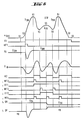
- a shows the time profile of the voltage signal u D (t) fed via the line 36 to the evaluation unit 35, which can be displayed with an oscilloscope (not shown here) connected to this unit.
- the curve point 51 corresponds to the position of the oil trap 10 'far above the UTP.
- the electrode 19 has a very small capacity against the piston rod 5; the frequency of the oscillator in unit 31 is high and the voltage at the output of the discriminator in unit 33 is at its negative saturation.
- the discriminator voltage u D is initially present at the input of a comparator Kl. As soon as this voltage has risen slightly above the negative saturation value 51 in accordance with the point 52 of the curve in FIG. 6a, the comparator Kl tilts in the positive direction (FIG. 6b). This triggers a monoflop MF1. The short pulse L1 generated in this way erases the CM voltage value stored in the previous piston stroke in a peak value detector PD. If the signal voltage u rises to the apex 53, this new value remains stored in the peak value detector PD; this value is designated û DM .
- a differentiation stage Q is provided, in which the signal u D (t) is differentiated electronically.
- the output voltage of the differentiating stage Q goes from u D to zero at every vertex (point 5?, 55, 57) or valley (point 54, 56) (FIG. 6e). As this figure shows, the output voltage changes the sign from minus to plus at the peaks (points 53, 55, 57) and from plus to minus at the valleys (points 54, 56).
- a comparator F2 (FIG.
- the circuit logic following this comparator ensures that a sample-and-hold circuit SH is one Receives sample command only in the UTP (point 55 in Fig. 6a), with which the value ü DV is recorded and stored.
- the circuit logic contains three monoflops MF2, MF3 and MF4, which are first activated by the comparator Kl as soon as its output signal at point 52 becomes larger (FIGS. 6g, i, l). Thus, these monoflops can only act during the measurement phase, which extends from points 51 to 59, corresponding to the movement of the oil trap 10 'in the area of the UTP.
- the output signal of the comparator K2 drops and triggers the monoflop MF3 (FIG. 6i), which in turn sets the flip-flop FF2 (FIG. 6k) with a short pulse; this flip-flop blocks the monoflop MF2 against further triggering.
- the output signal of the comparator K2 rises again and triggers the monoflop MF4 again (FIG. 61).
- the short pulse of the monoflop MF 4 now passes through the AND gate A opened by the flip-flops FF1 and FF2 to the sample-and-hold circuit SH (FIG. 5) and effects a detection of the peak value û DV , which then remains saved.
- the new peak values of u D ' which correspond to the capacitances of the measuring capacitor CM or the comparison capacitor CV, are stored in the UTP in the peak value detector PD or in the sample-and-hold circuit SH.
- a differential amplifier DV (Fig. 5) forms the difference u B.
- the individual u o values are switched electronically by the same clock generator; which switches over the four coupling capacitors.
- a low-pass filter TPF (FIG. 5) smoothes the by refreshing the voltage values in the peak value detector PD or in the sample-and-hold circuit SH conditional voltage jumps.
- the signal is displayed with the instrument 36 via a power amplifier EV connected to the low-pass filter TPF.
- a comparator K3 with an adjustable threshold which is also connected to the low-pass filter TPF, the alarm device 38 can be switched on via a relay R when a certain limit value of u B is reached.
- the average frequency of the HF oscillator contained in the unit 31 can shift over a longer period of time due to thermal changes in the capacitances of the measuring capacitor CM, the comparative capacitor CV and the coupling capacitor CK as well as changes in the elements of the oscillator itself.
- the circuit in the evaluation unit 35 forms the difference between the capacitances of the measuring and comparison capacitors, it is expedient to track the frequency discriminator in the unit 33 to the drift of the oscillator frequency.
- the peak voltage u DV formed by the sample-and-hold circuit SH is fed back to the unit 33 via a line 40 (FIG. 4) and used to correct the basic level of the signal u D (t) . This level is thus corrected so that the voltage value ü DV remains at a constant level.
- the oscillator itself can be corrected by feeding the voltage u DV back to unit 31 via cable 32 or 34 and using it to regulate the frequency, for example by means of a capacitance diode.
- the circuit described has the advantage that it detects the point in time at which the peak value (point 55 in FIG. 6a) occurs without detecting the UTP on the compressor by other means.
Landscapes
- Engineering & Computer Science (AREA)
- Mechanical Engineering (AREA)
- General Engineering & Computer Science (AREA)
- Investigating Or Analyzing Materials By The Use Of Electric Means (AREA)
- Measurement Of Length, Angles, Or The Like Using Electric Or Magnetic Means (AREA)
- Compressor (AREA)
- Compressors, Vaccum Pumps And Other Relevant Systems (AREA)
Priority Applications (1)
| Application Number | Priority Date | Filing Date | Title |
|---|---|---|---|
| AT83103698T ATE30938T1 (de) | 1982-05-18 | 1983-04-16 | Schmiermittel-ueberwachungsanordnung an einem kolbenkompressor. |
Applications Claiming Priority (2)
| Application Number | Priority Date | Filing Date | Title |
|---|---|---|---|
| CH3076/82 | 1982-05-18 | ||
| CH3076/82A CH657437A5 (de) | 1982-05-18 | 1982-05-18 | Schmiermittel-ueberwachungsanordnung an einem kolbenkompressor. |
Publications (3)
| Publication Number | Publication Date |
|---|---|
| EP0095037A2 true EP0095037A2 (fr) | 1983-11-30 |
| EP0095037A3 EP0095037A3 (en) | 1986-01-22 |
| EP0095037B1 EP0095037B1 (fr) | 1987-11-19 |
Family
ID=4248094
Family Applications (1)
| Application Number | Title | Priority Date | Filing Date |
|---|---|---|---|
| EP83103698A Expired EP0095037B1 (fr) | 1982-05-18 | 1983-04-16 | Dispositif de surveillance du lubrifiant dans un compresseur à piston |
Country Status (6)
| Country | Link |
|---|---|
| US (1) | US4505186A (fr) |
| EP (1) | EP0095037B1 (fr) |
| AT (1) | ATE30938T1 (fr) |
| CA (1) | CA1194579A (fr) |
| CH (1) | CH657437A5 (fr) |
| DE (1) | DE3220829C2 (fr) |
Cited By (1)
| Publication number | Priority date | Publication date | Assignee | Title |
|---|---|---|---|---|
| DE19503864A1 (de) * | 1995-02-07 | 1996-08-08 | Kamat Pumpen Gmbh & Co Kg | Überwachung des Verschleißes von Pumpendichtungen |
Families Citing this family (10)
| Publication number | Priority date | Publication date | Assignee | Title |
|---|---|---|---|---|
| US5331841A (en) * | 1991-02-11 | 1994-07-26 | Albemarle Corporation | Method and apparatus for repairing vessel ports |
| US5149105A (en) * | 1991-02-11 | 1992-09-22 | Ethyl Corporation | Method and apparatus for repairing vessels |
| US6394758B1 (en) * | 2000-11-14 | 2002-05-28 | Jae Young Lee | Apparatus and method of controlling air compressor |
| DE10314924B4 (de) * | 2003-04-01 | 2005-06-09 | Carl Freudenberg Kg | Einrichtung zur Erfassung einer Leckage |
| DE102004063229B4 (de) * | 2004-12-22 | 2007-06-14 | Hauni Maschinenbau Ag | Meßvorrichtung und -verfahren zur Erkennung von Fremdkörpern in einem Produkt, insbesondere in Tabak, Baumwolle oder einem anderen Faserprodukt |
| DE102004063228B4 (de) * | 2004-12-22 | 2007-06-28 | Hauni Maschinenbau Ag | Meßvorrichtung und -verfahren zur Bestimmung einer dielektrischen Eigenschaft, insbesondere der Feuchte und/oder Dichte, eines Produkts |
| DE102006000747B4 (de) * | 2006-01-04 | 2020-12-10 | Robert Bosch Gmbh | Antriebseinheit für Hydraulik-Kolbenpumpen eines Fahrzeugbremssystems mit Flüssigkeit aufsaugendem Mittel innerhalb des Exzenterraums |
| CN201035276Y (zh) * | 2007-05-15 | 2008-03-12 | 北京京东方光电科技有限公司 | 高节拍翻转装置 |
| US8264347B2 (en) * | 2008-06-24 | 2012-09-11 | Trelleborg Sealing Solutions Us, Inc. | Seal system in situ lifetime measurement |
| AT524547B1 (de) * | 2021-06-28 | 2022-07-15 | Hoerbiger Wien Gmbh | Kolbenkompressor und Verfahren zum Betreiben eines Kolbenkompressors |
Family Cites Families (10)
| Publication number | Priority date | Publication date | Assignee | Title |
|---|---|---|---|---|
| DE1083480B (de) * | 1953-05-26 | 1960-06-15 | Sulzer Ag | Kolbenkompressor |
| US2878990A (en) * | 1953-10-30 | 1959-03-24 | Sulzer Ag | Upright piston compressor |
| DE1132681B (de) * | 1958-10-24 | 1962-07-05 | Linde Eismasch Ag | Stopfbuechsenanordnung fuer die Kolbenstange von Trockenlaufverdichter |
| GB1185827A (en) * | 1966-04-07 | 1970-03-25 | Findlay Irvine Ltd | Improvements in Temperature and Moisture-Indicating and Control Apparatus |
| CA932353A (en) * | 1971-12-20 | 1973-08-21 | W. Mattoon Roland | Stuffing box assembly |
| DE2343752A1 (de) * | 1973-08-30 | 1975-03-13 | Eickhoff Geb | Antriebsmotor fuer im untertagebergbau eingesetzte gewinnungsmaschinen, insbesondere walzenschraemmaschinen |
| US3887196A (en) * | 1973-10-09 | 1975-06-03 | William Neil Renfrow | Self aligning stuffing box |
| DE2544730A1 (de) * | 1975-10-07 | 1977-04-21 | Basf Ag | Einrichtung zur fortlaufenden ueberwachung von oelleckagen an sauerstoff-verdichtern |
| JPS5856105B2 (ja) * | 1977-06-02 | 1983-12-13 | 東和電気株式会社 | 検知ケ−ブルによる漏洩事故検出方法 |
| CH627251A5 (en) * | 1978-01-30 | 1981-12-31 | Burckhardt Ag Maschf | Device for monitoring a cylinder lubricating pump which feeds a small quantity of lubricating oil under high pressure to the piston of a compressor |
-
1982
- 1982-05-18 CH CH3076/82A patent/CH657437A5/de not_active IP Right Cessation
- 1982-06-03 DE DE3220829A patent/DE3220829C2/de not_active Expired
-
1983
- 1983-04-16 AT AT83103698T patent/ATE30938T1/de not_active IP Right Cessation
- 1983-04-16 EP EP83103698A patent/EP0095037B1/fr not_active Expired
- 1983-05-13 CA CA000428105A patent/CA1194579A/fr not_active Expired
- 1983-05-18 US US06/495,934 patent/US4505186A/en not_active Expired - Fee Related
Cited By (1)
| Publication number | Priority date | Publication date | Assignee | Title |
|---|---|---|---|---|
| DE19503864A1 (de) * | 1995-02-07 | 1996-08-08 | Kamat Pumpen Gmbh & Co Kg | Überwachung des Verschleißes von Pumpendichtungen |
Also Published As
| Publication number | Publication date |
|---|---|
| CA1194579A (fr) | 1985-10-01 |
| DE3220829C2 (de) | 1984-04-12 |
| US4505186A (en) | 1985-03-19 |
| EP0095037B1 (fr) | 1987-11-19 |
| ATE30938T1 (de) | 1987-12-15 |
| DE3220829A1 (de) | 1983-12-08 |
| CH657437A5 (de) | 1986-08-29 |
| EP0095037A3 (en) | 1986-01-22 |
Similar Documents
| Publication | Publication Date | Title |
|---|---|---|
| EP0095037B1 (fr) | Dispositif de surveillance du lubrifiant dans un compresseur à piston | |
| DE19701899C2 (de) | Schaltungsanordnung und Verfahren zur Erfassung der Kapazität bzw. einer Kapazitätsänderung eines kapazitiven Schaltungs- oder Bauelementes | |
| EP0568973B1 (fr) | Interrupteur de niveau | |
| DE1573198A1 (de) | Einrichtung zum Verhindern der Kondensation von Feuchtigkeit und der Eisbildung auf einer Flaeche | |
| CH617010A5 (fr) | ||
| EP3926230B1 (fr) | Procédé de détection d'une matière | |
| EP0118147B1 (fr) | Dispositif de résistance de mesure et d'amortissement pour un appareil à haute tension | |
| DE2815686B2 (de) | Vorrichtung zur Überwachung der Population von tierischen Schädlingen, insbesondere von ausgewählten Insektenarten | |
| DE2354839A1 (de) | Kapazitaetsempfindliches messgeraet zur messung physikalischer groessen | |
| DE692964C (de) | ungen | |
| EP0030520B1 (fr) | Procédé et dispositif pour l'examen d'un matériau support en bande revêtu pour la détermination de la présence de défauts allongés du revêtement | |
| WO1985004718A1 (fr) | Detecteur pour l'analyse de liquides | |
| DE2608760A1 (de) | Einrichtung und verfahren zum nachweis von aerosolen | |
| DE1977607U (de) | Messgefaess fuer eine einrichtung zum zaehlen von suspendierten teilchen. | |
| EP0384209A2 (fr) | Procédé pour l'opération d'un détecteur de fumée à ionisation et détecteur de fumée à ionisation | |
| CH615784A5 (en) | Monitoring arrangement on an overvoltage arrester containing at least one spark gap | |
| DE2924556A1 (de) | Fuellstandsanzeigeeinrichtung | |
| DE3722059C1 (en) | Measuring device for fluid jets | |
| DE2111438A1 (de) | Katodenstrahlroehre fuer punktweise Darstellung | |
| EP0030387A2 (fr) | Affichage analogique de la tension à cristaux liquides | |
| DE1808324A1 (de) | Vorrichtung zur UEberwachung wenigstens einer physikalischen Groesse | |
| DE749825C (de) | Spannungsanzeigeroehre, insbesondere Abstimmanzeigeroehre | |
| DE3206916C1 (de) | Radargerät | |
| DE2251046B2 (de) | Rauchgasanzeiger | |
| DE624457C (de) | Regelkondensator aus anorganischem, insbesondere keramischem Isolierstoff mit geringen dielektrischen Verlusten roehrenfoermiger Bauart |
Legal Events
| Date | Code | Title | Description |
|---|---|---|---|
| PUAI | Public reference made under article 153(3) epc to a published international application that has entered the european phase |
Free format text: ORIGINAL CODE: 0009012 |
|
| AK | Designated contracting states |
Designated state(s): AT BE FR GB IT SE |
|
| PUAL | Search report despatched |
Free format text: ORIGINAL CODE: 0009013 |
|
| AK | Designated contracting states |
Designated state(s): AT BE FR GB IT SE |
|
| 17P | Request for examination filed |
Effective date: 19860502 |
|
| 17Q | First examination report despatched |
Effective date: 19861030 |
|
| ITF | It: translation for a ep patent filed | ||
| GRAA | (expected) grant |
Free format text: ORIGINAL CODE: 0009210 |
|
| AK | Designated contracting states |
Kind code of ref document: B1 Designated state(s): AT BE FR GB IT SE |
|
| REF | Corresponds to: |
Ref document number: 30938 Country of ref document: AT Date of ref document: 19871215 Kind code of ref document: T |
|
| ET | Fr: translation filed | ||
| GBT | Gb: translation of ep patent filed (gb section 77(6)(a)/1977) | ||
| PLBE | No opposition filed within time limit |
Free format text: ORIGINAL CODE: 0009261 |
|
| STAA | Information on the status of an ep patent application or granted ep patent |
Free format text: STATUS: NO OPPOSITION FILED WITHIN TIME LIMIT |
|
| 26N | No opposition filed | ||
| ITTA | It: last paid annual fee | ||
| EAL | Se: european patent in force in sweden |
Ref document number: 83103698.3 |
|
| PGFP | Annual fee paid to national office [announced via postgrant information from national office to epo] |
Ref country code: GB Payment date: 19960313 Year of fee payment: 14 |
|
| PGFP | Annual fee paid to national office [announced via postgrant information from national office to epo] |
Ref country code: FR Payment date: 19960318 Year of fee payment: 14 Ref country code: BE Payment date: 19960318 Year of fee payment: 14 |
|
| PGFP | Annual fee paid to national office [announced via postgrant information from national office to epo] |
Ref country code: SE Payment date: 19960321 Year of fee payment: 14 |
|
| PGFP | Annual fee paid to national office [announced via postgrant information from national office to epo] |
Ref country code: AT Payment date: 19960322 Year of fee payment: 14 |
|
| PG25 | Lapsed in a contracting state [announced via postgrant information from national office to epo] |
Ref country code: GB Effective date: 19970416 Ref country code: AT Effective date: 19970416 |
|
| PG25 | Lapsed in a contracting state [announced via postgrant information from national office to epo] |
Ref country code: SE Effective date: 19970417 |
|
| PG25 | Lapsed in a contracting state [announced via postgrant information from national office to epo] |
Ref country code: BE Effective date: 19970430 |
|
| BERE | Be: lapsed |
Owner name: MASCHINENFABRIK SULZER-BURCKHARDT A.G. Effective date: 19970430 |
|
| GBPC | Gb: european patent ceased through non-payment of renewal fee |
Effective date: 19970416 |
|
| PG25 | Lapsed in a contracting state [announced via postgrant information from national office to epo] |
Ref country code: FR Free format text: LAPSE BECAUSE OF NON-PAYMENT OF DUE FEES Effective date: 19971231 |
|
| EUG | Se: european patent has lapsed |
Ref document number: 83103698.3 |
|
| REG | Reference to a national code |
Ref country code: FR Ref legal event code: ST |