EP0095090A2 - Dispositif pour favoriser l'extinction d'arc dans des dispositifs de commutation tels que disjoncteurs électriques - Google Patents
Dispositif pour favoriser l'extinction d'arc dans des dispositifs de commutation tels que disjoncteurs électriques Download PDFInfo
- Publication number
- EP0095090A2 EP0095090A2 EP83104625A EP83104625A EP0095090A2 EP 0095090 A2 EP0095090 A2 EP 0095090A2 EP 83104625 A EP83104625 A EP 83104625A EP 83104625 A EP83104625 A EP 83104625A EP 0095090 A2 EP0095090 A2 EP 0095090A2
- Authority
- EP
- European Patent Office
- Prior art keywords
- arc
- insulating material
- improved arrangement
- extinction
- blow out
- Prior art date
- Legal status (The legal status is an assumption and is not a legal conclusion. Google has not performed a legal analysis and makes no representation as to the accuracy of the status listed.)
- Granted
Links
Images
Classifications
-
- H—ELECTRICITY
- H01—ELECTRIC ELEMENTS
- H01H—ELECTRIC SWITCHES; RELAYS; SELECTORS; EMERGENCY PROTECTIVE DEVICES
- H01H9/00—Details of switching devices, not covered by groups H01H1/00 - H01H7/00
- H01H9/30—Means for extinguishing or preventing arc between current-carrying parts
- H01H9/44—Means for extinguishing or preventing arc between current-carrying parts using blow-out magnet
- H01H9/446—Means for extinguishing or preventing arc between current-carrying parts using blow-out magnet using magnetisable elements associated with the contacts
-
- H—ELECTRICITY
- H01—ELECTRIC ELEMENTS
- H01H—ELECTRIC SWITCHES; RELAYS; SELECTORS; EMERGENCY PROTECTIVE DEVICES
- H01H9/00—Details of switching devices, not covered by groups H01H1/00 - H01H7/00
- H01H9/30—Means for extinguishing or preventing arc between current-carrying parts
- H01H9/302—Means for extinguishing or preventing arc between current-carrying parts wherein arc-extinguishing gas is evolved from stationary parts
-
- H—ELECTRICITY
- H01—ELECTRIC ELEMENTS
- H01H—ELECTRIC SWITCHES; RELAYS; SELECTORS; EMERGENCY PROTECTIVE DEVICES
- H01H3/00—Mechanisms for operating contacts
- H01H3/02—Operating parts, i.e. for operating driving mechanism by a mechanical force external to the switch
- H01H3/0253—Operating parts, i.e. for operating driving mechanism by a mechanical force external to the switch two co-operating contacts actuated independently
Definitions
- This invention is related to the subject matter of EPO 033 4790 Al (81100416.7) entitled “Arc extinguishing arrangement in electric circuit breakers", filed January 21, 1981, having as applicant the same applicant of the instant application, which is incorporated herein for purposes of reference.
- This invention relates in general to the magnetic motoring assembly shown at Fig. 1 in the aforementioned Patent Application and, in particular, to the insulating material forming a coating and filling the gaps existing between the plates of magnetic material of the side magnetic assembly, in such a manner as to form an arc as described in the aforementioned patent application, and also to the arc motivating assembly shown at Fig. 12, particularly the material forming the two columns flanking the side assembly.
- the insulating material forming the columns of the assembly must satisfy two contradictory requirements, namely, a high electrical insul ation and a high arc resistance while at the same time contribute substantially to the blow out and extinction of the arc by the vaporization of gases.
- the insulating substances known in the art will either provide the high insulation coefficient and high arc resistance, while slightly contributing to the blow out and extinction of the arc, of the arc, or they vaporize and contribute to the blow out and extinction of the arc but are incapable of maintaining their properties after exposure to the arc.
- One of the main objects of this invention is to provide the insulation which is necessary between the contacts of a circuit breaker when the contacts are open and, at the same time, to develop effective blow out ' and extinction of the arcing between the contacts when opened.
- the insulating material forming a coating and filling the gaps existing between the plates of magnetic material which comprise the magnetic or side assembly is selected and arranged in such a manner as to contribute to the extinction of the arc by vaporization and emission of gas and,at the same time, to prevent formation of flame and the conductive paths which can decrease the insulation required between the contacts when they are opened.
- the insulating material is selected from two different types and, in one embodiment of the invention, is arranged with at least two alternate layers on the columns of the magnetic assembly.
- the first material (28') has a high dielectric strength and a high arc resistance while incapable of emitting gas to assist in the blow out and extinction of the arc. However this material does not form paths of low electrical resistance which would decrease the necessary insulation between the open contacts of the circuit breaker.
- the second material (28") does actively contribute to the blow out and extinction of the arc by vaporization and emission of gas without having to maintan its insulating properties after exposure to the arc, since it is not relied upon to maintain the insulation between the open contacts.
- the two types of insulating material are arranged in three alternative layers consisting of two end layers (28') of the first material separated by an intermediate layer (28") of the second material.
- the second mate rial is positioned adjacent the location where the arcing occurs for immediately contributing to the blow out and extinguishing the arc upon the instance of arc formation.
- the two end layers (28') of the first ma terial of the first type provide the necessary insulation between the open contacts.
- the two types of insulating material are alternated to form a plurality of layers in order to allow a distribution of both the arc blow out and extinction property and the electrical insulating property along the entire length of the columns of the magnetic assembly.
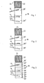
- a pair of contacts comprising a movable contact 12 and a stationary (or semi-stationary) contact 14, is flanked by a magnetic assembly 18.
- the side assembly is usually bridged by a ma gnetic yoke consisting of laminations 22 coated with insulating mate rial 14, and, as described in the aforementioned Patent Application,con sists of plates of coated ferromagnetic material embedded in insulating resinous material indicated at 28' and 28".
- the resinous material is of two different types.
- the first indicated at 28' is a material with high dielectric' strength and high arc resistance which, under the influence of the arc, may or may not emit gas for extinction of the arc but, must not form tracks of low electrical resistance which would decrease the required insulation between the open contacts.
- the type indicated at 28" contributes to the extinction of the arc by vaporization and emission of gas during arcing, while not having to maintain its insulating properties after the arc is extinguished since it is not required to substain the insulation between the open contacts.
- the preferred material is a flame-retarding halogen-free polypropylene, for example, having flame-retarding properties by silica-based additives which, upon combustion, will not develop toxic or corrosive vapors or soot.
- This invention operates as follows: when a short-circuit occurs, the two contacts 12 and 14 will repel reaching the position 12 and 14a, res pectively, illustrated in the three figures. Immediately after the contacts become opened by repulsion, an electric arc is established between the open contacts which are flanked by materials 28' and 28" which are coated on the columns of the side assembly 18. The heat thus created by the arc will cause melting, vaporization and/or decomposition of material 28", along with emission of gas which will urge or blow the arc thus contributing to its extinction.
- the layer of material 28" being close to the more stationary contact 14 which, upon repulsion due to a short-circuit, assumes the position indicated at 14a, urges the lower portion of the arc to the right, by driving it out of the magnetic assembly 18 and directing it toward an extinction assembly (not illustrated), while the layer of material 28' maintains the required insulation between the open contacts.
- the layer of material 28" is arranged in the center of the columns of the magnetic assembly 18, such that it will act on the central portion of the arc moving it to the right and driving it out of the magnetic assembly 18, while the two layers of material 28' maintain the required insulation between the open contacts.
- the plurality of layers of material 28" alternated with layers of material 28' on the columns of the magnetic assembly 18, causes the arc thrust or blow action to be distributed all along the length of the assembly of material 28', maintaining the required insulation between the open contacts.
Landscapes
- Arc-Extinguishing Devices That Are Switches (AREA)
- Driving Mechanisms And Operating Circuits Of Arc-Extinguishing High-Tension Switches (AREA)
- Insulated Conductors (AREA)
- Organic Insulating Materials (AREA)
- Gas-Insulated Switchgears (AREA)
- Fire-Extinguishing Compositions (AREA)
- Breakers (AREA)
Priority Applications (1)
| Application Number | Priority Date | Filing Date | Title |
|---|---|---|---|
| AT83104625T ATE39594T1 (de) | 1982-05-25 | 1983-05-11 | Einrichtung zum foerdern der lichtbogenloeschung in schaltvorrichtungen, sowie elektrische schaltschutze. |
Applications Claiming Priority (2)
| Application Number | Priority Date | Filing Date | Title |
|---|---|---|---|
| IT21463/82A IT1151231B (it) | 1982-05-25 | 1982-05-25 | Perfezionata disposizione atta ad esaltare il soffio e/o l'estinzione d'arco ora i contatti |
| IT2146382 | 1982-05-25 |
Publications (3)
| Publication Number | Publication Date |
|---|---|
| EP0095090A2 true EP0095090A2 (fr) | 1983-11-30 |
| EP0095090A3 EP0095090A3 (en) | 1985-08-07 |
| EP0095090B1 EP0095090B1 (fr) | 1988-12-28 |
Family
ID=11182174
Family Applications (1)
| Application Number | Title | Priority Date | Filing Date |
|---|---|---|---|
| EP83104625A Expired EP0095090B1 (fr) | 1982-05-25 | 1983-05-11 | Dispositif pour favoriser l'extinction d'arc dans des dispositifs de commutation tels que disjoncteurs électriques |
Country Status (9)
| Country | Link |
|---|---|
| US (1) | US4492836A (fr) |
| EP (1) | EP0095090B1 (fr) |
| JP (1) | JPS58214229A (fr) |
| AT (1) | ATE39594T1 (fr) |
| BR (1) | BR8302635A (fr) |
| CA (1) | CA1222787A (fr) |
| DE (1) | DE3378803D1 (fr) |
| ES (1) | ES8404104A1 (fr) |
| IT (1) | IT1151231B (fr) |
Cited By (3)
| Publication number | Priority date | Publication date | Assignee | Title |
|---|---|---|---|---|
| WO1986001934A1 (fr) * | 1984-09-13 | 1986-03-27 | Doduco Kg Dr. Eugen Dürrwächter | Interrupteur a reponse automatique, permettant de limiter le courant |
| EP0350823A3 (fr) * | 1988-07-15 | 1991-03-20 | Asea Brown Boveri Aktiengesellschaft | Interrupteur à basse tension |
| EP0567614A4 (fr) * | 1991-10-18 | 1994-05-04 | Square D Company |
Families Citing this family (4)
| Publication number | Priority date | Publication date | Assignee | Title |
|---|---|---|---|---|
| FR2679965A1 (fr) * | 1991-07-31 | 1993-02-05 | Bretagne Baches Sa | Dispositif pour l'assemblage d'une toile sur sa structure porteuse et moyens de solidarisation d'un tel dispositif sur la toile. |
| US5875885A (en) * | 1997-05-28 | 1999-03-02 | Eaton Corporation | Combined wire lead and interphase barrier for power switches |
| US6060674A (en) * | 1997-05-28 | 2000-05-09 | Eaton Corporation | Circuit interrupter with plasma arc acceleration chamber and contact arm housing |
| DE10331822A1 (de) | 2003-07-14 | 2005-02-10 | Siemens Ag | Schiffs-Leistungsschalter sowie einen solchen enthaltende Schiffs-Energieversorgungs- und -verteilungsanlage |
Family Cites Families (7)
| Publication number | Priority date | Publication date | Assignee | Title |
|---|---|---|---|---|
| US2082028A (en) * | 1932-04-15 | 1937-06-01 | Westinghouse Electric & Mfg Co | Plunger-type current interrupter |
| US2707218A (en) * | 1951-05-31 | 1955-04-26 | Westinghouse Electric Corp | Air-break circuit interrupters |
| DE966575C (de) * | 1955-09-01 | 1957-08-22 | Voigt & Haeffner Ag | Schaltkammer, insbesondere fuer Installationsselbstschalter in Schraubstoepselform |
| US3248511A (en) * | 1963-01-18 | 1966-04-26 | Heinemann Electric Co | Terminals and improved handle for circuit breakers |
| US3582586A (en) * | 1966-03-21 | 1971-06-01 | Rostone Corp | Arc-interrupting materials and apparatus |
| FR2475290A1 (fr) * | 1980-01-31 | 1981-08-07 | Merlin Gerin | Chambre de coupure de disjoncteurs basse tension a joues composites de guidage de l'arc |
| IT1129691B (it) * | 1980-01-31 | 1986-06-11 | Elettromeccanica Spa Cge Comp | Complesso di estinzione rapida dell'arco elettrico in dispositivi di interruzione come interruttori elettrici |
-
1982
- 1982-05-25 IT IT21463/82A patent/IT1151231B/it active
-
1983
- 1983-02-28 US US06/470,678 patent/US4492836A/en not_active Expired - Fee Related
- 1983-05-11 EP EP83104625A patent/EP0095090B1/fr not_active Expired
- 1983-05-11 DE DE8383104625T patent/DE3378803D1/de not_active Expired
- 1983-05-11 AT AT83104625T patent/ATE39594T1/de active
- 1983-05-17 BR BR8302635A patent/BR8302635A/pt unknown
- 1983-05-20 CA CA000428639A patent/CA1222787A/fr not_active Expired
- 1983-05-24 JP JP58090122A patent/JPS58214229A/ja active Pending
- 1983-05-24 ES ES522649A patent/ES8404104A1/es not_active Expired
Cited By (3)
| Publication number | Priority date | Publication date | Assignee | Title |
|---|---|---|---|---|
| WO1986001934A1 (fr) * | 1984-09-13 | 1986-03-27 | Doduco Kg Dr. Eugen Dürrwächter | Interrupteur a reponse automatique, permettant de limiter le courant |
| EP0350823A3 (fr) * | 1988-07-15 | 1991-03-20 | Asea Brown Boveri Aktiengesellschaft | Interrupteur à basse tension |
| EP0567614A4 (fr) * | 1991-10-18 | 1994-05-04 | Square D Company |
Also Published As
| Publication number | Publication date |
|---|---|
| EP0095090A3 (en) | 1985-08-07 |
| IT8221463A0 (it) | 1982-05-25 |
| ES522649A0 (es) | 1984-04-16 |
| JPS58214229A (ja) | 1983-12-13 |
| DE3378803D1 (en) | 1989-02-02 |
| ATE39594T1 (de) | 1989-01-15 |
| ES8404104A1 (es) | 1984-04-16 |
| EP0095090B1 (fr) | 1988-12-28 |
| CA1222787A (fr) | 1987-06-09 |
| BR8302635A (pt) | 1984-01-17 |
| US4492836A (en) | 1985-01-08 |
| IT1151231B (it) | 1986-12-17 |
Similar Documents
| Publication | Publication Date | Title |
|---|---|---|
| EP0033479B1 (fr) | Dispositif d'extinction d'arc pour disjoncteurs limiteurs de courant électrique | |
| US5326947A (en) | Arc extinguishing device made of conductive plastic | |
| US4950852A (en) | Electric circuit breaker arc chute composition | |
| US2236580A (en) | Circuit interrupter | |
| US20090255904A1 (en) | Arc splitter arrangement for an electrical switch | |
| US4885441A (en) | Circuit Breaker | |
| EP0095090A2 (fr) | Dispositif pour favoriser l'extinction d'arc dans des dispositifs de commutation tels que disjoncteurs électriques | |
| GB388175A (en) | Improvements in or relating to electric circuit breakers having arc-rupturing devices | |
| CA1086804A (fr) | Commutateurs a vide | |
| CN1469405A (zh) | 用于开关或断路器等电力保护设备的真空管壳 | |
| US7863537B2 (en) | Gassing insulator assembly, and conductor assembly and electrical switching apparatus employing the same | |
| CA1220248A (fr) | Coupe-circuit miniature a niveau d'isolement ameliore | |
| EP0288040B1 (fr) | Disjoncteur | |
| CN1238879C (zh) | 电弧熄灭装置 | |
| US20090321393A1 (en) | Current-limiting arc-quenching device | |
| US4409444A (en) | Circuit breaker | |
| US3538279A (en) | Blowout magnet structure for air-break circuit interrupter | |
| US7154061B2 (en) | Interrupter assembly for a circuit breaker | |
| HUP0002992A2 (hu) | Ívoltó lemezcsomag villamos kapcsolókészülékekhez | |
| JPH02117025A (ja) | 接触ブレード用隔離装置 | |
| KR880001791Y1 (ko) | 회로 차단기 | |
| JPH04315714A (ja) | 低電圧遮断器 | |
| US622511A (en) | Electric safety fuse or cut-out | |
| CN116844892A (zh) | 电器开关 | |
| JPS58133731A (ja) | 開閉器 |
Legal Events
| Date | Code | Title | Description |
|---|---|---|---|
| PUAI | Public reference made under article 153(3) epc to a published international application that has entered the european phase |
Free format text: ORIGINAL CODE: 0009012 |
|
| AK | Designated contracting states |
Designated state(s): AT BE CH DE FR GB LI NL SE |
|
| PUAL | Search report despatched |
Free format text: ORIGINAL CODE: 0009013 |
|
| AK | Designated contracting states |
Designated state(s): AT BE CH DE FR GB LI NL SE |
|
| 17P | Request for examination filed |
Effective date: 19860121 |
|
| 17Q | First examination report despatched |
Effective date: 19870602 |
|
| GRAA | (expected) grant |
Free format text: ORIGINAL CODE: 0009210 |
|
| AK | Designated contracting states |
Kind code of ref document: B1 Designated state(s): AT BE CH DE FR GB LI NL SE |
|
| REF | Corresponds to: |
Ref document number: 39594 Country of ref document: AT Date of ref document: 19890115 Kind code of ref document: T |
|
| REF | Corresponds to: |
Ref document number: 3378803 Country of ref document: DE Date of ref document: 19890202 |
|
| ET | Fr: translation filed | ||
| PLBE | No opposition filed within time limit |
Free format text: ORIGINAL CODE: 0009261 |
|
| STAA | Information on the status of an ep patent application or granted ep patent |
Free format text: STATUS: NO OPPOSITION FILED WITHIN TIME LIMIT |
|
| 26N | No opposition filed | ||
| PGFP | Annual fee paid to national office [announced via postgrant information from national office to epo] |
Ref country code: AT Payment date: 19920512 Year of fee payment: 10 |
|
| PGFP | Annual fee paid to national office [announced via postgrant information from national office to epo] |
Ref country code: NL Payment date: 19920531 Year of fee payment: 10 |
|
| PGFP | Annual fee paid to national office [announced via postgrant information from national office to epo] |
Ref country code: GB Payment date: 19920924 Year of fee payment: 10 |
|
| PG25 | Lapsed in a contracting state [announced via postgrant information from national office to epo] |
Ref country code: GB Effective date: 19930511 Ref country code: AT Effective date: 19930511 |
|
| PG25 | Lapsed in a contracting state [announced via postgrant information from national office to epo] |
Ref country code: NL Effective date: 19931201 |
|
| GBPC | Gb: european patent ceased through non-payment of renewal fee |
Effective date: 19930511 |
|
| NLV4 | Nl: lapsed or anulled due to non-payment of the annual fee | ||
| PGFP | Annual fee paid to national office [announced via postgrant information from national office to epo] |
Ref country code: BE Payment date: 19940328 Year of fee payment: 12 |
|
| PGFP | Annual fee paid to national office [announced via postgrant information from national office to epo] |
Ref country code: SE Payment date: 19940509 Year of fee payment: 12 |
|
| PGFP | Annual fee paid to national office [announced via postgrant information from national office to epo] |
Ref country code: CH Payment date: 19940826 Year of fee payment: 12 |
|
| EAL | Se: european patent in force in sweden |
Ref document number: 83104625.5 |
|
| PG25 | Lapsed in a contracting state [announced via postgrant information from national office to epo] |
Ref country code: SE Effective date: 19950512 |
|
| PG25 | Lapsed in a contracting state [announced via postgrant information from national office to epo] |
Ref country code: LI Effective date: 19950531 Ref country code: CH Effective date: 19950531 Ref country code: BE Effective date: 19950531 |
|
| BERE | Be: lapsed |
Owner name: CGE- COMPAGNIA GENERALE ELETTROMECCANICA S.P.A. Effective date: 19950531 |
|
| REG | Reference to a national code |
Ref country code: CH Ref legal event code: PL |
|
| EUG | Se: european patent has lapsed |
Ref document number: 83104625.5 |
|
| PGFP | Annual fee paid to national office [announced via postgrant information from national office to epo] |
Ref country code: FR Payment date: 20020322 Year of fee payment: 20 |
|
| PGFP | Annual fee paid to national office [announced via postgrant information from national office to epo] |
Ref country code: DE Payment date: 20020731 Year of fee payment: 20 |