EP0095145A2 - Vorrichtung zum Zuführen und Versprühen von Ätznatronschmelze - Google Patents
Vorrichtung zum Zuführen und Versprühen von Ätznatronschmelze Download PDFInfo
- Publication number
- EP0095145A2 EP0095145A2 EP83104947A EP83104947A EP0095145A2 EP 0095145 A2 EP0095145 A2 EP 0095145A2 EP 83104947 A EP83104947 A EP 83104947A EP 83104947 A EP83104947 A EP 83104947A EP 0095145 A2 EP0095145 A2 EP 0095145A2
- Authority
- EP
- European Patent Office
- Prior art keywords
- caustic soda
- spraying
- glassy carbon
- delivering
- soda solution
- Prior art date
- Legal status (The legal status is an assumption and is not a legal conclusion. Google has not performed a legal analysis and makes no representation as to the accuracy of the status listed.)
- Granted
Links
Images

Classifications
-
- B—PERFORMING OPERATIONS; TRANSPORTING
- B05—SPRAYING OR ATOMISING IN GENERAL; APPLYING FLUENT MATERIALS TO SURFACES, IN GENERAL
- B05B—SPRAYING APPARATUS; ATOMISING APPARATUS; NOZZLES
- B05B3/00—Spraying or sprinkling apparatus with moving outlet elements or moving deflecting elements
- B05B3/02—Spraying or sprinkling apparatus with moving outlet elements or moving deflecting elements with rotating elements
- B05B3/10—Spraying or sprinkling apparatus with moving outlet elements or moving deflecting elements with rotating elements discharging over substantially the whole periphery of the rotating member
- B05B3/1057—Spraying or sprinkling apparatus with moving outlet elements or moving deflecting elements with rotating elements discharging over substantially the whole periphery of the rotating member with at least two outlets, other than gas and cleaning fluid outlets, for discharging, selectively or not, different or identical liquids or other fluent materials on the rotating element
-
- B—PERFORMING OPERATIONS; TRANSPORTING
- B01—PHYSICAL OR CHEMICAL PROCESSES OR APPARATUS IN GENERAL
- B01J—CHEMICAL OR PHYSICAL PROCESSES, e.g. CATALYSIS OR COLLOID CHEMISTRY; THEIR RELEVANT APPARATUS
- B01J19/00—Chemical, physical or physico-chemical processes in general; Their relevant apparatus
- B01J19/02—Apparatus characterised by being constructed of material selected for its chemically-resistant properties
-
- B—PERFORMING OPERATIONS; TRANSPORTING
- B01—PHYSICAL OR CHEMICAL PROCESSES OR APPARATUS IN GENERAL
- B01J—CHEMICAL OR PHYSICAL PROCESSES, e.g. CATALYSIS OR COLLOID CHEMISTRY; THEIR RELEVANT APPARATUS
- B01J2/00—Processes or devices for granulating materials, e.g. fertilisers in general; Rendering particulate materials free flowing in general, e.g. making them hydrophobic
- B01J2/02—Processes or devices for granulating materials, e.g. fertilisers in general; Rendering particulate materials free flowing in general, e.g. making them hydrophobic by dividing the liquid material into drops, e.g. by spraying, and solidifying the drops
- B01J2/04—Processes or devices for granulating materials, e.g. fertilisers in general; Rendering particulate materials free flowing in general, e.g. making them hydrophobic by dividing the liquid material into drops, e.g. by spraying, and solidifying the drops in a gaseous medium
-
- B—PERFORMING OPERATIONS; TRANSPORTING
- B05—SPRAYING OR ATOMISING IN GENERAL; APPLYING FLUENT MATERIALS TO SURFACES, IN GENERAL
- B05B—SPRAYING APPARATUS; ATOMISING APPARATUS; NOZZLES
- B05B1/00—Nozzles, spray heads or other outlets, with or without auxiliary devices such as valves, heating means
- B05B1/14—Nozzles, spray heads or other outlets, with or without auxiliary devices such as valves, heating means with multiple outlet openings; with strainers in or outside the outlet opening
-
- B—PERFORMING OPERATIONS; TRANSPORTING
- B05—SPRAYING OR ATOMISING IN GENERAL; APPLYING FLUENT MATERIALS TO SURFACES, IN GENERAL
- B05B—SPRAYING APPARATUS; ATOMISING APPARATUS; NOZZLES
- B05B3/00—Spraying or sprinkling apparatus with moving outlet elements or moving deflecting elements
- B05B3/02—Spraying or sprinkling apparatus with moving outlet elements or moving deflecting elements with rotating elements
- B05B3/10—Spraying or sprinkling apparatus with moving outlet elements or moving deflecting elements with rotating elements discharging over substantially the whole periphery of the rotating member
- B05B3/1007—Spraying or sprinkling apparatus with moving outlet elements or moving deflecting elements with rotating elements discharging over substantially the whole periphery of the rotating member characterised by the rotating member
- B05B3/1021—Spraying or sprinkling apparatus with moving outlet elements or moving deflecting elements with rotating elements discharging over substantially the whole periphery of the rotating member characterised by the rotating member with individual passages at its periphery
-
- C—CHEMISTRY; METALLURGY
- C01—INORGANIC CHEMISTRY
- C01D—COMPOUNDS OF ALKALI METALS, i.e. LITHIUM, SODIUM, POTASSIUM, RUBIDIUM, CAESIUM, OR FRANCIUM
- C01D1/00—Oxides or hydroxides of sodium, potassium or alkali metals in general
- C01D1/04—Hydroxides
- C01D1/42—Concentration; Dehydration
-
- B—PERFORMING OPERATIONS; TRANSPORTING
- B01—PHYSICAL OR CHEMICAL PROCESSES OR APPARATUS IN GENERAL
- B01J—CHEMICAL OR PHYSICAL PROCESSES, e.g. CATALYSIS OR COLLOID CHEMISTRY; THEIR RELEVANT APPARATUS
- B01J2219/00—Chemical, physical or physico-chemical processes in general; Their relevant apparatus
- B01J2219/02—Apparatus characterised by their chemically-resistant properties
- B01J2219/0204—Apparatus characterised by their chemically-resistant properties comprising coatings on the surfaces in direct contact with the reactive components
-
- B—PERFORMING OPERATIONS; TRANSPORTING
- B01—PHYSICAL OR CHEMICAL PROCESSES OR APPARATUS IN GENERAL
- B01J—CHEMICAL OR PHYSICAL PROCESSES, e.g. CATALYSIS OR COLLOID CHEMISTRY; THEIR RELEVANT APPARATUS
- B01J2219/00—Chemical, physical or physico-chemical processes in general; Their relevant apparatus
- B01J2219/02—Apparatus characterised by their chemically-resistant properties
- B01J2219/0204—Apparatus characterised by their chemically-resistant properties comprising coatings on the surfaces in direct contact with the reactive components
- B01J2219/0227—Apparatus characterised by their chemically-resistant properties comprising coatings on the surfaces in direct contact with the reactive components of graphite
Definitions
- the invention relates to a device for supplying and spraying caustic soda melt, which essentially consists of an alkali pump and a spray basket.
- caustic soda When producing solid caustic soda by the prilling process, caustic soda is melted by means of a lye pump, e.g. a submersible pump, a spray basket, with which it is divided into individual droplets at the head of a prilling tower. It has been shown that the device parts, in particular with the flowing. Caustic soda and possibly also come into contact with oxygen, are subject to considerable wear and tear, even though they are made of stainless steel, nickel, nickel alloys, silver or precious metal alloys.
- the object is achieved in that the parts of the device which come into direct contact with the caustic soda consist of glassy carbon or are coated with glassy carbon.
- All parts of the device such as parts of pumps, orifices, pipes, elbows, fittings, spray baskets, etc., which come into contact with caustic soda, can be made of glass carbon exist or be coated with glassy carbon.
- Figure 1 shows a spray basket for caustic soda melt.
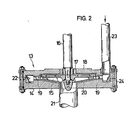
- Figure 2 shows a submersible pump for caustic soda.
- the spray basket ( Figure 1) consists of a sleeve 1 for receiving the drive shaft (not shown) and the bottom part 2.
- the jacket 4 of the basket made of glassy carbon sits with the holes 10 through which the caustic soda melt is atomized.
- the cover 4 is held by a cover, a ring 3 and the anchors consisting of bolts 5, washers 6 and nuts 7.
- the bottom part 2 and the sleeve 1 are protected by a sleeve 8 and the bolts 5 by sleeves 9 made of glassy carbon.
- 11 are the feed lines for the caustic soda melt, which protrude through an annular gap 12 into the spray basket.
- the pump housing of the submersible pump (FIG. 2) consists of the guide device 13 and the suction cover 14.
- the hub of the impeller 15 protrudes through the guide device 13, consisting of the pump housing 18, bushing 17 and the guide vanes 19, and receives the drive shaft.
- the guide device 13 has a sleeve 17 for protecting the pump housing part 18.
- the bushing 17 carries guide vanes 19.
- the suction cover 14 is provided with a bushing 20 which protects the cover 14 and whose connecting piece 21 serves as a suction pipe for the caustic soda melt.
- Suction cover 14 and pump housing part 18 delimit an annular channel 22, via which the caustic soda melt is fed to an outlet nozzle 23.
- a guide ring 24 is arranged in the ring channel 22.
- Bushing 17 with guide vanes 19, bushing 20 with connecting piece 21 and pump impeller are made of glassy carbon.
- the guide ring 24 can also consist of glassy carbon.
Landscapes
- Chemical & Material Sciences (AREA)
- Organic Chemistry (AREA)
- Chemical Kinetics & Catalysis (AREA)
- Engineering & Computer Science (AREA)
- Materials Engineering (AREA)
- Inorganic Chemistry (AREA)
- Structures Of Non-Positive Displacement Pumps (AREA)
- Processing Of Solid Wastes (AREA)
- Processing And Handling Of Plastics And Other Materials For Molding In General (AREA)
- Coating By Spraying Or Casting (AREA)
- Detergent Compositions (AREA)
- Breeding Of Plants And Reproduction By Means Of Culturing (AREA)
- Micro-Organisms Or Cultivation Processes Thereof (AREA)
- Medicines Containing Material From Animals Or Micro-Organisms (AREA)
- Furnace Housings, Linings, Walls, And Ceilings (AREA)
- Application Of Or Painting With Fluid Materials (AREA)
- Nozzles (AREA)
- Glanulating (AREA)
Abstract
Description
- Gegenstand der Erfindung ist eine Vorrichtung zum Zuführen und Versprühen von Ätznatronschmelze, die im wesentlichen aus Laugepumpe und Sprühkorb besteht.
- Beim Herstellen von festem Ätznatron nach dem Prillverfahren wird Ätznatronschmelze mittels einer Laugepumpe, z.B. einer Tauchpumpe, einem Sprühkorb zugeführt, mit dem sie am Kopf eines Prillturmes in einzelne Tröpfchen aufgeteilt wird. Dabei hat sich gezeigt, daß die Vorrichtungsteile, die insbesondere mit der strömenden . Ätznatronlauge und gegebenenfalls zusätzlich mit Sauerstoff in Berührung kommen, einem erheblichen Verschleiß unterliegen, obwohl sie aus Edelstahl, Nickel, Nickellegierungen, Silber oder Edelmetallegierungen hergestellt sind.
- Es bestand demnach die Aufgabe, eine Vorrichtung zu schaffen, deren Teile, die mit Ätznatronschmelze in Berührung kommen, weitgehend gegen Verschleiß geschützt sind.
- Die Aufgabe wird erfindungsgemäß dadurch gelöst, daß die Teile der Vorrichtung, die mit der Ätznatronschmelze direkt in Berührung kommen, aus Glaskohlenstoff bestehen oder mit Glaskohlenstoff beschichtet sind.
- Alle Teile der Vorrichtung wie Teile von Pumpen, Blenden, Rohre, Rohrkrümmer, Armaturen, Sprühkörbe usw., die mit Ätznatronschmelze in Berührung kommen, können aus Glaskohlenstoff bestehen bzw. mit Glaskohlenstoff beschichtet werden.
- Im folgenden wird die Erfindung anhand zweier Beispiele näher erläutert.
- Figur 1 zeigt einen Sprühkorb für Ätznatronschmelze. Figur 2 zeigt eine Tauchpumpe für Ätznatronschmelze.
- Der Sprühkorb (Figur 1) besteht aus einer Hülse 1 zur Aufnahme der Antriebswelle (nicht dargestellt) und des Bodenteils 2. Auf dem Bodenteil 2 sitzt der Mantel 4 des Korbes aus Glaskohlenstoff mit den Löchern 10, durch die die Ätznatronschmelze zerstäubt wird. Durch eine Abdeckung, einen Ring 3, und die Anker bestehend aus Bolzen 5, Unterlegscheiben 6 und Muttern 7, wird der Mantel 4 gehalten. Das Bodenteil 2 und die Hülse 1 sind durch eine Büchse 8 und die Bolzen 5 durch Hülsen 9 aus Glaskohlenstoff geschützt. 11 sind die Zuleitungen für die Ätznatronschmelze, die durch einen Ringspalt 12 in den Sprühkorb ragen.
- Das Pumpengehäuse der Tauchpumpe (Figur 2) besteht aus der Leiteinrichtung 13 und dem Saugdeckel 14. Die Nabe des Laufrades 15 ragt durch die Leiteinrichtung 13, bestehend aus Pumpengehäuse 18, Büchse 17 und den Leitschaufeln 19, hindurch und nimmt die Antriebswelle auf. Die Leiteinrichtung 13 weist eine Büchse 17 zum Schutz des Pumpengehäuseteiles 18 auf. Die Büchse 17 trägt Leitschaufeln 19. Ebenso ist der Saugdeckel 14 mit einer Büchse 20 versehen, die den Deckel 14 schützt und deren Stutzen 21 als Saugrohr für die Ätznatronschmelze dient. Saugdeckel 14 und Pumpengehäuseteil 18 begrenzen einen Ringkanal 22, über den die Ätznatronschmelze einem Auslaßstutzen 23 zugeführt wird. Im Ringkanal 22 ist ein Leitring 24 angeordnet.
- Büchse 17 mit Leitschaufeln 19, Büchse 20 mit Stutzen 21 und Pumpenlaufrad sind aus Glaskohlenstoff gefertigt. Der Leitring 24 kann ebenfalls aus Glaskohlenstoff bestehen.
Claims (2)
die Teile der Vorrichtung, die mit der Ätznatronschmelze direkt in Berührung kommen, mit Glaskohlenstoff beschichtet sind.
die Teile der Vorrichtung, die mit der Ätznatronschmelze direkt in Berührung kommen aus Glaskohlenstoff bestehen.
Priority Applications (1)
| Application Number | Priority Date | Filing Date | Title |
|---|---|---|---|
| AT83104947T ATE18513T1 (de) | 1982-05-25 | 1983-05-19 | Vorrichtung zum zufuehren und verspruehen von aetznatronschmelze. |
Applications Claiming Priority (2)
| Application Number | Priority Date | Filing Date | Title |
|---|---|---|---|
| DE3219497 | 1982-05-25 | ||
| DE19823219497 DE3219497A1 (de) | 1982-05-25 | 1982-05-25 | Vorrichtung zum zufuehren und verspruehen von aetznatronschmelze |
Publications (3)
| Publication Number | Publication Date |
|---|---|
| EP0095145A2 true EP0095145A2 (de) | 1983-11-30 |
| EP0095145A3 EP0095145A3 (en) | 1984-05-02 |
| EP0095145B1 EP0095145B1 (de) | 1986-03-12 |
Family
ID=6164373
Family Applications (1)
| Application Number | Title | Priority Date | Filing Date |
|---|---|---|---|
| EP83104947A Expired EP0095145B1 (de) | 1982-05-25 | 1983-05-19 | Vorrichtung zum Zuführen und Versprühen von Ätznatronschmelze |
Country Status (8)
| Country | Link |
|---|---|
| EP (1) | EP0095145B1 (de) |
| JP (1) | JPS58208134A (de) |
| AT (1) | ATE18513T1 (de) |
| CA (1) | CA1197959A (de) |
| DE (2) | DE3219497A1 (de) |
| FI (1) | FI72901C (de) |
| NO (1) | NO161615C (de) |
| ZA (1) | ZA833722B (de) |
Cited By (2)
| Publication number | Priority date | Publication date | Assignee | Title |
|---|---|---|---|---|
| EP0362746A3 (en) * | 1988-10-07 | 1990-06-27 | Benckiser-Knapsack Gmbh | Apparatus and process for the preparation of alkali metal monofluorophosphate |
| WO2000058004A1 (de) * | 1999-03-29 | 2000-10-05 | Bk Giulini Chemie Gmbh & Co. Ohg | Vorrichtung zur herstellung von korrosiven phosphatschmelzen |
Families Citing this family (2)
| Publication number | Priority date | Publication date | Assignee | Title |
|---|---|---|---|---|
| DE4439924A1 (de) * | 1994-11-08 | 1996-05-09 | Bayerische Motoren Werke Ag | Verwendung von kohlenstoffhaltigen Schichten |
| DE19801700A1 (de) * | 1998-01-17 | 1999-07-22 | Cit Alcatel | Vorrichtung zum Beschichten einer Faser |
Family Cites Families (3)
| Publication number | Priority date | Publication date | Assignee | Title |
|---|---|---|---|---|
| FR1475809A (fr) * | 1966-02-17 | 1967-04-07 | Lorraine Carbone | Application du carbone vitreux à la fabrication de filières, guide-fils, pièces d'usure |
| US3733151A (en) * | 1972-03-01 | 1973-05-15 | Dow Chemical Co | Pump assembly for handling liquid materials |
| DE2451969C2 (de) * | 1974-10-30 | 1976-11-08 | Aerospace Corp | Verfahren zum glasieren von werkstuecken aus keramik, kohle oder kohlenstoff |
-
1982
- 1982-05-25 DE DE19823219497 patent/DE3219497A1/de not_active Withdrawn
-
1983
- 1983-05-19 DE DE8383104947T patent/DE3362521D1/de not_active Expired
- 1983-05-19 AT AT83104947T patent/ATE18513T1/de not_active IP Right Cessation
- 1983-05-19 EP EP83104947A patent/EP0095145B1/de not_active Expired
- 1983-05-23 FI FI831830A patent/FI72901C/fi not_active IP Right Cessation
- 1983-05-24 NO NO831837A patent/NO161615C/no unknown
- 1983-05-24 CA CA000428692A patent/CA1197959A/en not_active Expired
- 1983-05-24 JP JP58090152A patent/JPS58208134A/ja active Pending
- 1983-05-24 ZA ZA833722A patent/ZA833722B/xx unknown
Cited By (2)
| Publication number | Priority date | Publication date | Assignee | Title |
|---|---|---|---|---|
| EP0362746A3 (en) * | 1988-10-07 | 1990-06-27 | Benckiser-Knapsack Gmbh | Apparatus and process for the preparation of alkali metal monofluorophosphate |
| WO2000058004A1 (de) * | 1999-03-29 | 2000-10-05 | Bk Giulini Chemie Gmbh & Co. Ohg | Vorrichtung zur herstellung von korrosiven phosphatschmelzen |
Also Published As
| Publication number | Publication date |
|---|---|
| FI831830A0 (fi) | 1983-05-23 |
| NO831837L (no) | 1983-11-28 |
| ZA833722B (en) | 1985-01-30 |
| CA1197959A (en) | 1985-12-17 |
| FI831830L (fi) | 1983-11-26 |
| EP0095145A3 (en) | 1984-05-02 |
| NO161615B (no) | 1989-05-29 |
| DE3219497A1 (de) | 1983-12-01 |
| NO161615C (no) | 1989-09-06 |
| EP0095145B1 (de) | 1986-03-12 |
| FI72901C (fi) | 1987-08-10 |
| DE3362521D1 (en) | 1986-04-17 |
| FI72901B (fi) | 1987-04-30 |
| JPS58208134A (ja) | 1983-12-03 |
| ATE18513T1 (de) | 1986-03-15 |
Similar Documents
| Publication | Publication Date | Title |
|---|---|---|
| DE3347064C2 (de) | Vorrichtung für die mechanische Reinigung von in einer Kühlwasserleitung geführtem Kühlwasser von Kraftwerkskondensatoren | |
| DE2726800A1 (de) | Vorrichtung zum reinigen von ruehrgutbehaeltern | |
| DE19520616A1 (de) | Düse für einen Schweißbrenner | |
| EP0095145B1 (de) | Vorrichtung zum Zuführen und Versprühen von Ätznatronschmelze | |
| EP0111057A1 (de) | Verfahren und Vorrichtung zur Herstellung eines Rohrkrümmers aus Stahl | |
| EP0365964B1 (de) | Strahlrohr | |
| WO1982001482A1 (en) | Method and installation for the processing of the upper side of a flat part by means of a liquid | |
| CN215878508U (zh) | 一种自动化防锈油喷淋装置 | |
| EP0278322A2 (de) | Vorrichtung zur Sprühbeschichtung von Gefässmündungen | |
| DE3600920C2 (de) | ||
| DE60305163T2 (de) | Abgedichteter propeller zum erzeugen von metallschaum und dazugehörendes system | |
| AT404686B (de) | Sprühnebelführungshülse | |
| CH641252A5 (de) | Vorrichtung zur gasdynamischen durchmischung von fluessigem metall in einem behaelter. | |
| DE2355961A1 (de) | Zerstaeubungsvorrichtung an einem zahnaerztlichen handbohrgeraet | |
| EP0103037B1 (de) | Brennschneidmaschine | |
| DE699770C (de) | Verfahren zur Hochkonzentration von Schwefelsaeure und aehnlichen angreifenden Fluessigkeiten | |
| DE19619693A1 (de) | Schutzgas-Schweißbrenner und Steuer- bzw. Regeleinheit | |
| DE722490C (de) | Umlaufender Spritzkopf fuer Farbspritzanlagen | |
| DE2818720B1 (de) | Verfahren und Vorrichtung zur Herstellung von Metallpulver | |
| EP0493695A3 (en) | Process and apparatus for obtaining protection coatings | |
| CN208099444U (zh) | 一种钢管加工设备 | |
| DE240354C (de) | ||
| DE1126891B (de) | ||
| DE2121439B2 (de) | Verfahren zum Umschmelzen von Blöcken mittels Plasmastrahlen | |
| DD215326B3 (de) | Austrags- und kuehlvorrichtung fuer heisse reaktionsgase |
Legal Events
| Date | Code | Title | Description |
|---|---|---|---|
| PUAI | Public reference made under article 153(3) epc to a published international application that has entered the european phase |
Free format text: ORIGINAL CODE: 0009012 |
|
| AK | Designated contracting states |
Designated state(s): AT BE CH DE FR GB IT LI NL SE |
|
| PUAL | Search report despatched |
Free format text: ORIGINAL CODE: 0009013 |
|
| AK | Designated contracting states |
Designated state(s): AT BE CH DE FR GB IT LI NL SE |
|
| 17P | Request for examination filed |
Effective date: 19840926 |
|
| GRAA | (expected) grant |
Free format text: ORIGINAL CODE: 0009210 |
|
| AK | Designated contracting states |
Kind code of ref document: B1 Designated state(s): AT BE CH DE FR GB IT LI NL SE |
|
| REF | Corresponds to: |
Ref document number: 18513 Country of ref document: AT Date of ref document: 19860315 Kind code of ref document: T |
|
| REF | Corresponds to: |
Ref document number: 3362521 Country of ref document: DE Date of ref document: 19860417 |
|
| ITF | It: translation for a ep patent filed | ||
| ET | Fr: translation filed | ||
| PLBE | No opposition filed within time limit |
Free format text: ORIGINAL CODE: 0009261 |
|
| STAA | Information on the status of an ep patent application or granted ep patent |
Free format text: STATUS: NO OPPOSITION FILED WITHIN TIME LIMIT |
|
| 26N | No opposition filed | ||
| ITTA | It: last paid annual fee | ||
| PGFP | Annual fee paid to national office [announced via postgrant information from national office to epo] |
Ref country code: FR Payment date: 19920410 Year of fee payment: 10 |
|
| PGFP | Annual fee paid to national office [announced via postgrant information from national office to epo] |
Ref country code: CH Payment date: 19920413 Year of fee payment: 10 |
|
| PGFP | Annual fee paid to national office [announced via postgrant information from national office to epo] |
Ref country code: SE Payment date: 19920415 Year of fee payment: 10 |
|
| PGFP | Annual fee paid to national office [announced via postgrant information from national office to epo] |
Ref country code: GB Payment date: 19920416 Year of fee payment: 10 |
|
| PGFP | Annual fee paid to national office [announced via postgrant information from national office to epo] |
Ref country code: AT Payment date: 19920424 Year of fee payment: 10 |
|
| PGFP | Annual fee paid to national office [announced via postgrant information from national office to epo] |
Ref country code: BE Payment date: 19920504 Year of fee payment: 10 |
|
| PGFP | Annual fee paid to national office [announced via postgrant information from national office to epo] |
Ref country code: NL Payment date: 19920531 Year of fee payment: 10 |
|
| PGFP | Annual fee paid to national office [announced via postgrant information from national office to epo] |
Ref country code: DE Payment date: 19920711 Year of fee payment: 10 |
|
| PG25 | Lapsed in a contracting state [announced via postgrant information from national office to epo] |
Ref country code: GB Effective date: 19930519 Ref country code: AT Effective date: 19930519 |
|
| PG25 | Lapsed in a contracting state [announced via postgrant information from national office to epo] |
Ref country code: SE Effective date: 19930520 |
|
| PG25 | Lapsed in a contracting state [announced via postgrant information from national office to epo] |
Ref country code: LI Effective date: 19930531 Ref country code: CH Effective date: 19930531 Ref country code: BE Effective date: 19930531 |
|
| BERE | Be: lapsed |
Owner name: HOECHST A.G. Effective date: 19930531 |
|
| PG25 | Lapsed in a contracting state [announced via postgrant information from national office to epo] |
Ref country code: NL Effective date: 19931201 |
|
| NLV4 | Nl: lapsed or anulled due to non-payment of the annual fee | ||
| GBPC | Gb: european patent ceased through non-payment of renewal fee |
Effective date: 19930519 |
|
| PG25 | Lapsed in a contracting state [announced via postgrant information from national office to epo] |
Ref country code: FR Effective date: 19940131 |
|
| REG | Reference to a national code |
Ref country code: CH Ref legal event code: PL |
|
| PG25 | Lapsed in a contracting state [announced via postgrant information from national office to epo] |
Ref country code: DE Effective date: 19940201 |
|
| REG | Reference to a national code |
Ref country code: FR Ref legal event code: ST |
|
| EUG | Se: european patent has lapsed |
Ref document number: 83104947.3 Effective date: 19931210 |