EP0095213A2 - Vorrichtung für die Entleerung von Flaschen aus einem Behälter und die Aufrechtstellung auf einem Gurtförderer - Google Patents
Vorrichtung für die Entleerung von Flaschen aus einem Behälter und die Aufrechtstellung auf einem Gurtförderer Download PDFInfo
- Publication number
- EP0095213A2 EP0095213A2 EP83200703A EP83200703A EP0095213A2 EP 0095213 A2 EP0095213 A2 EP 0095213A2 EP 83200703 A EP83200703 A EP 83200703A EP 83200703 A EP83200703 A EP 83200703A EP 0095213 A2 EP0095213 A2 EP 0095213A2
- Authority
- EP
- European Patent Office
- Prior art keywords
- boxes
- conveyor
- bottles
- cage
- machine
- Prior art date
- Legal status (The legal status is an assumption and is not a legal conclusion. Google has not performed a legal analysis and makes no representation as to the accuracy of the status listed.)
- Withdrawn
Links
Images



Classifications
-
- B—PERFORMING OPERATIONS; TRANSPORTING
- B65—CONVEYING; PACKING; STORING; HANDLING THIN OR FILAMENTARY MATERIAL
- B65G—TRANSPORT OR STORAGE DEVICES, e.g. CONVEYORS FOR LOADING OR TIPPING, SHOP CONVEYOR SYSTEMS OR PNEUMATIC TUBE CONVEYORS
- B65G47/00—Article or material-handling devices associated with conveyors; Methods employing such devices
- B65G47/02—Devices for feeding articles or materials to conveyors
- B65G47/04—Devices for feeding articles or materials to conveyors for feeding articles
- B65G47/12—Devices for feeding articles or materials to conveyors for feeding articles from disorderly-arranged article piles or from loose assemblages of articles
- B65G47/14—Devices for feeding articles or materials to conveyors for feeding articles from disorderly-arranged article piles or from loose assemblages of articles arranging or orientating the articles by mechanical or pneumatic means during feeding
- B65G47/1492—Devices for feeding articles or materials to conveyors for feeding articles from disorderly-arranged article piles or from loose assemblages of articles arranging or orientating the articles by mechanical or pneumatic means during feeding the articles being fed from a feeding conveyor
-
- B—PERFORMING OPERATIONS; TRANSPORTING
- B65—CONVEYING; PACKING; STORING; HANDLING THIN OR FILAMENTARY MATERIAL
- B65G—TRANSPORT OR STORAGE DEVICES, e.g. CONVEYORS FOR LOADING OR TIPPING, SHOP CONVEYOR SYSTEMS OR PNEUMATIC TUBE CONVEYORS
- B65G47/00—Article or material-handling devices associated with conveyors; Methods employing such devices
- B65G47/02—Devices for feeding articles or materials to conveyors
- B65G47/04—Devices for feeding articles or materials to conveyors for feeding articles
- B65G47/12—Devices for feeding articles or materials to conveyors for feeding articles from disorderly-arranged article piles or from loose assemblages of articles
- B65G47/14—Devices for feeding articles or materials to conveyors for feeding articles from disorderly-arranged article piles or from loose assemblages of articles arranging or orientating the articles by mechanical or pneumatic means during feeding
- B65G47/1407—Devices for feeding articles or materials to conveyors for feeding articles from disorderly-arranged article piles or from loose assemblages of articles arranging or orientating the articles by mechanical or pneumatic means during feeding the articles being fed from a container, e.g. a bowl
- B65G47/1442—Devices for feeding articles or materials to conveyors for feeding articles from disorderly-arranged article piles or from loose assemblages of articles arranging or orientating the articles by mechanical or pneumatic means during feeding the articles being fed from a container, e.g. a bowl by means of movement of the bottom or a part of the wall of the container
- B65G47/1471—Movement in one direction, substantially outwards
Definitions
- the present invention obviates the aforesaid drawbacks by providing a machine able to automatically and rapidly effect the aforesaid operations by means of a simple and rational design.
- the proposed machine comprises a roller table for feeding the receptacles in which the containers are randomly accumulated, the roller table serving a type of cage into which the receptacles are inserted in turn, and are then overturned in an upward direction so that their mouth becomes inclined to the vertical.
- the cage comprises a cover arranged to close the mouth of the receptacles, and two elevators are disposed in a fixed position to the side of the overturned cage in order to extract the receptacles from the cage.
- the mouths of the receptacles withdraw from said cover in order to discharge the containers on to an underlying conveyor provided with longitudinal channels and with deviator members arranged to cause the containers to penetrate into said channels.
- the channels can comprise walls at different speeds.
- the empty receptacles are discharged from the elevators on to a holding surface above the channel conveyor, this latter depositing the containers side-by-side and parallel to each other o" to a further conveyor provided with an orientation device. This latter disposes all the containers with their base downwards so that they become deposited in an upright position on a discharge belt.
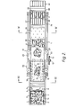
- Figures 1 and 2 show a base frame 1, from the front end of which there branches a roller feed table 2 which is slightly inclined downwards in the downstream direction.
- a roller feed table 2 On the roller feed table 2 are placed large receptacles 3, for example in the form of boxes or chests, in which containers 4, represented by bottles in this specific case, are randomly amassed.
- the roller feed table 2 comprises a first central aperture 5 provided with two lateral jutting roller sections 6 and in which there is a stop device 7 for the chests 3, comprising a vertically mobile transverse bar (Figure 2) of which the movements are controlled by an underlying piston-cylinder unit (not shown).
- the blocking movements of the stop 7 are determined by a feeler 8 ( Figure 1), ana the distance between the stop device 7 and the downstream end of the roller table 2 is greater than the longitudinal dimension of the boxes or chests 3 in order to allow them to swivel upwards without impact.
- the downstream end of the roller feed table 2 comprises a central longitudinal aperture 9, see Figure 3, which is bounded laterally by two jutting roller sections 10.
- the roller feed table 2 is provided laterally with longitudinal guides 11 for centering the chests 3, and above its downstream end there is disposed a cage which is hinged to the frame 1 on a transverse horizontal shaft 12.
- the cage comprises a lower fork 15 ( Figures 2 and 3) designed for insertion into the longitudinal aperture 9 to become disposed slightly below the jutting roller sections 10, and further comprises a rear orthogonal wall 16, and an upper plate 17 parallel to the fork 15 to act as a cover for the chests 3 ( Figure 1).
- a cross member 18 of the frame 1 where there is also provided a feeler 19 arranged to detect the presence of a chest inside the cage, and to cause this latter to rotate upwards.
- the total rotation of the cage is 120° ( Figure 1), so that the cover 17 becomes disposed in perfect alignment with two angular slide tracks 18 fixed to a framework 79 branching upwards from the frame 1.
- the distance between said tracks is practically equal to the width of the chests 3.
- a portal 20 of which the uprights are each provided with two end sprocket wheels 21 with a respective endless chain 22.
- the two chains 22 lie in the same plane inclined to the vertical, at a distance from the tracks 18 which is practically equal to one half the depth of the chests 3 ( Figure 1).
- Each chain 22 is provided with two right angled members 23 which project outwards and are arranged to extract the chests 3 from the cage 15, 16, 17, when this latter is in its raised position ( Figures 1 and 3).
- the lower sprocket wheels 21 are idle, whereas the upper ones are the drive wheels and are both driven by way of a transmission, not shown in the figure, from a geared motor 24 supported by the portal 20.
- Figure 1 also shows that the cross member of the portal 20 is configured as a fork disposed orthogonally to the uprights in order to allow passage of the empty chests 3 during the discharge stage.
- a feeler 25 which causes the drive unit 140 to stop and the geared motor 24 to start.
- two opposing right angled members 23 raise the chest 3, so extracting it from the cage, and the bottles 4 pass beyond the tracks 18 to fall on to an underlying horizontal conveyor 26.
- the bottles 4 discharged from the chest 3 accumulate on the upper horizontal portion of the conveyor 26, which comprises a belt passing about two transverse horizontal drums 30, of which the downstream drum is driven by a geared motor unit 31 ( Figure 1).
- the outer surface of the belt 26 is provided with equidistant longitudinal ribs 32 ( Figure 4), between each pair of which there is defined a longitudinal channel 33.
- a plate 34 Downstream of the collection zone for the bottles 4, as shown in Figures 1, 2 and 4, there is disposed above the conveyor 26 a plate 34 which is provided lowerly with four transverse rows of vertical rods 35, which extend until they practically make contact with the ribs 32.
- the rods 35 of each row are distributed at a constant pitch, and adjacent rows are mutually staggered.
- the distribution pitch of the rods in the rows is practically equal to the length of a bottle 4.
- the thickness of the rods 35 is such as to allow passage of the correctly orientated bottles located in the two channels 33 which straddle each individual rod ( Figure 4).
- the conveyor for collecting the bottles 4 comprises two side pieces 202 on which there is idly mounted a first horizontal transverse shaft 203 on which there is keyed a series of sprocket wheels 204 (Figure 5).
- Said side pieces 202 support a second transverse shaft 205, provided with an end sprocket wheel 206 about which there passes a chain 207 which passes about a pinion 208. This latter is keyed to the end of an intermediate shaft 209 disposed at the same level as the shafts 203 and 205.
- a second pinion 288 ( Figure 6) about which there passes a chain 210 which also passes about a sprocket wheel 211 driven by a geared motor with incorporated variator 212, which is fixed to the framework 79.
- a series of sprocket wheels of number equal to the number of sprocket wheels 204. More specifically, said series of sprocket wheels comprises five sprocket wheels 213 keyed on to the shaft 5 and four idle sprocket wheels 230 interspersed with the sprocket wheels 213.
- the sprocket wheels 213 and 230 have the same pitch circle diameter (Figure 6), which is also equal to that of the sprocket wheels 204. Between the upstream sprocket wheels 204 and the downstream sprocket wheels 213 and 230 there extend respective endless chains 214, to the links of each of which there is externally fixed a plurality of equal equidistant profiled members 215, of stylised "omega" configuration ( Figure 6).
- the profiled members 215 have their concavity facing the corresponding chain, and are symmetrically disposed with respect to this latter. In this manner, between each pair of chains there is defined a longitudinal channel 216 for receiving the containers 4.
- the upper rectilinear branch of the said conveyor comprises two longitudinal retaining walls 218.
- a pinion 233 about which there passes a chain 219, and which has a pitch circle diameter less than that of the sprocket wheels 213, 230.
- the chains 219 pass about respective drive pinions 220 rigid with the intermediate shaft 209 ( Figure 5).
- a structure 221 which supports a series of vertical deviating rods 35 disposed as described heretofore with reference to Figures 2 and 4.
- the containers 4 which are not immediately inserted into said channels 216, and are therefore disposed transversely or obliquely to one of them, are made to rotate about themselves until they become disposed longitudinally, aided by the deviating rods 35, until said containers fall into the channels 216.
- the conveyor 26 or 214, 215 deposits the bottles 4, by way of a slide surface 223 ( Figure 5) on to a conveyor/spacer 36 ( Figures 1 and 5) which comprises a belt with transverse fins 38, and is driven by the said geared motor 31 or 212.
- the upper rectilinear portion of said conveyor/spacer 36 is divided into a series of longitudinal channels by suitable baffles 37 ( Figure 2). These channels are aligned with the channels 33, 216 of the conveyor 26, 214-215. Downstream of the conveyor 36 there is a normal orientation device, not shown, which for each individual channel of the conveyor 36 comprises a vertically swivelling retainer.
- the retainer swivels freely when a bottle 4 presents itself with its base pointing forwards, whereas otherwise it grips the neck of the bottle in order to invert this latter. In this manner all the bottles are discharged, with their base pointing downwards, into a multi-channel vertical conveyor 39 disposed below the conveyor/spacer 36, and which itself discharges the bottles upright on to an underlying conveyor belt 40, from which the bottles 4 proceed towards the other operating stations, for example towards a washing/sterilising machine.
- the fork 15 can be replaced by a roller section arranged for insertion into the aperture 9 in order to become disposed between the two opposing roller sections 10.
Landscapes
- Engineering & Computer Science (AREA)
- Mechanical Engineering (AREA)
- Attitude Control For Articles On Conveyors (AREA)
Applications Claiming Priority (4)
| Application Number | Priority Date | Filing Date | Title |
|---|---|---|---|
| IT46832/82A IT1159201B (it) | 1982-05-24 | 1982-05-24 | Macchina per estrarre le bottiglie contenute alla rinfusa nelle cassette,e porgerle allineate e diritte su un nastro |
| IT4683282 | 1982-05-24 | ||
| IT46855/82A IT1159215B (it) | 1982-08-27 | 1982-08-27 | Trasportatore a velocita' differenziale per allineare dei contenitori cilindrici adagiati di costa a partire dagli stessi ammassati alla rinfusa |
| IT4685582 | 1982-08-27 |
Publications (2)
| Publication Number | Publication Date |
|---|---|
| EP0095213A2 true EP0095213A2 (de) | 1983-11-30 |
| EP0095213A3 EP0095213A3 (de) | 1984-12-27 |
Family
ID=26329185
Family Applications (1)
| Application Number | Title | Priority Date | Filing Date |
|---|---|---|---|
| EP83200703A Withdrawn EP0095213A3 (de) | 1982-05-24 | 1983-05-17 | Vorrichtung für die Entleerung von Flaschen aus einem Behälter und die Aufrechtstellung auf einem Gurtförderer |
Country Status (1)
| Country | Link |
|---|---|
| EP (1) | EP0095213A3 (de) |
Cited By (5)
| Publication number | Priority date | Publication date | Assignee | Title |
|---|---|---|---|---|
| FR2558138A1 (fr) * | 1984-01-13 | 1985-07-19 | Squeri Donata & C Aicma Snc | Machine permettant de vider des caisses pleines de conteneurs, tels que des bouteilles et permettant le redressement et l'alignement des bouteilles chargees |
| EP0412043A1 (de) * | 1989-08-03 | 1991-02-06 | Jaime Marti Sala | Automatische Zuführvorrichtung einer Flaschenfüllstrasse |
| CN108175106A (zh) * | 2018-03-05 | 2018-06-19 | 北京林业大学 | 沙果去核机 |
| CN108382668A (zh) * | 2018-04-03 | 2018-08-10 | 广州市博仕机电工贸有限公司 | 一种无损伤瓶胚装箱系统 |
| CN112934430A (zh) * | 2021-01-25 | 2021-06-11 | 安徽理工大学 | 一种磷肥的制备装置及方法 |
Family Cites Families (6)
| Publication number | Priority date | Publication date | Assignee | Title |
|---|---|---|---|---|
| US2775334A (en) * | 1953-11-24 | 1956-12-25 | United Can And Glass Company | Can unscrambler |
| GB1233357A (de) * | 1969-07-15 | 1971-05-26 | ||
| FR2100993B1 (de) * | 1970-08-04 | 1974-09-20 | Thibault Jacque | |
| GB2047190A (en) * | 1979-04-05 | 1980-11-26 | Carter Bros Rochdale Ltd | Tipping containers carried by conveyors |
| US4328887A (en) * | 1980-04-07 | 1982-05-11 | Ethyl Development Corporation | Unscrambler-unloader |
| GB2101068A (en) * | 1981-06-29 | 1983-01-12 | Odenberg Investments Ltd | Can handling apparatus |
-
1983
- 1983-05-17 EP EP83200703A patent/EP0095213A3/de not_active Withdrawn
Cited By (7)
| Publication number | Priority date | Publication date | Assignee | Title |
|---|---|---|---|---|
| FR2558138A1 (fr) * | 1984-01-13 | 1985-07-19 | Squeri Donata & C Aicma Snc | Machine permettant de vider des caisses pleines de conteneurs, tels que des bouteilles et permettant le redressement et l'alignement des bouteilles chargees |
| EP0412043A1 (de) * | 1989-08-03 | 1991-02-06 | Jaime Marti Sala | Automatische Zuführvorrichtung einer Flaschenfüllstrasse |
| FR2650558A1 (fr) * | 1989-08-03 | 1991-02-08 | Sala Jaime Marti | Ensemble pour l'alimentation automatique d'une ligne d'embouteillage de recipients |
| CN108175106A (zh) * | 2018-03-05 | 2018-06-19 | 北京林业大学 | 沙果去核机 |
| CN108382668A (zh) * | 2018-04-03 | 2018-08-10 | 广州市博仕机电工贸有限公司 | 一种无损伤瓶胚装箱系统 |
| CN112934430A (zh) * | 2021-01-25 | 2021-06-11 | 安徽理工大学 | 一种磷肥的制备装置及方法 |
| CN112934430B (zh) * | 2021-01-25 | 2023-12-15 | 大有众和(北京)农业科技有限公司 | 一种磷肥的制备装置及方法 |
Also Published As
| Publication number | Publication date |
|---|---|
| EP0095213A3 (de) | 1984-12-27 |
Similar Documents
| Publication | Publication Date | Title |
|---|---|---|
| US2509069A (en) | Machine for sorting, counting, and packaging medicinal tablets | |
| US4627215A (en) | Apparatus for charging receptacles with stacked, flat items | |
| US3845852A (en) | Carton loader | |
| US7757465B2 (en) | Apparatus and method for filling containers with rod-shaped products | |
| US20120160638A1 (en) | Checkpoint system with wheeled bins | |
| US3517797A (en) | Thread bobbin tube aligner | |
| JPS58135025A (ja) | 瓶の整列移送方法及びその装置 | |
| EP0462497A1 (de) | Vorrichtung zum Aufrichten von Behältern | |
| US3143223A (en) | Method and means for packing articles of tapered shape | |
| CN108587871B (zh) | 一种自动化发酵系统 | |
| EP0095213A2 (de) | Vorrichtung für die Entleerung von Flaschen aus einem Behälter und die Aufrechtstellung auf einem Gurtförderer | |
| WO1995031376A1 (en) | Method and apparatus for inserting partition elements between articles | |
| CN216709744U (zh) | 一种面饼自动输送并投放料包设备 | |
| US1454051A (en) | Case-emptying machine | |
| CN210854193U (zh) | 一种用于整理瓶盖的输送带 | |
| US4648501A (en) | Apparatus for sorting and aligning handles for cardboard boxes or the like and for supplying such to an insertion apparatus | |
| US3688925A (en) | Plant for processing bulky masses, especially pelletized materials in autoclaves | |
| US3143232A (en) | Apparatus for transferring chocolate bars or the like from one conveying system to another | |
| CN109775015A (zh) | 一种双尖灯泡包装机 | |
| CN212173666U (zh) | 一种倒瓶自动扶正装置 | |
| US1905477A (en) | Brick edging machine | |
| EP1886946A1 (de) | Anlage zur Sortierung und Aufrichtung von Flaschen | |
| CA1047553A (en) | Machine for stacking cups | |
| CN207141518U (zh) | 一种香肠排序计数装置 | |
| US3389791A (en) | Flatware sorter |
Legal Events
| Date | Code | Title | Description |
|---|---|---|---|
| PUAI | Public reference made under article 153(3) epc to a published international application that has entered the european phase |
Free format text: ORIGINAL CODE: 0009012 |
|
| AK | Designated contracting states |
Designated state(s): AT BE CH DE FR GB LI LU NL SE |
|
| PUAL | Search report despatched |
Free format text: ORIGINAL CODE: 0009013 |
|
| AK | Designated contracting states |
Designated state(s): AT BE CH DE FR GB LI LU NL SE |
|
| 17P | Request for examination filed |
Effective date: 19850507 |
|
| 17Q | First examination report despatched |
Effective date: 19860321 |
|
| STAA | Information on the status of an ep patent application or granted ep patent |
Free format text: STATUS: THE APPLICATION IS DEEMED TO BE WITHDRAWN |
|
| 18D | Application deemed to be withdrawn |
Effective date: 19860701 |
|
| RIN1 | Information on inventor provided before grant (corrected) |
Inventor name: DONATO, SQUERI |