EP0095227A1 - Verfahren zur Bestimmung der Bindungsqualität zwischen zwei Bauelementen mit Hilfe der thermoakustischen Mikroskopie - Google Patents
Verfahren zur Bestimmung der Bindungsqualität zwischen zwei Bauelementen mit Hilfe der thermoakustischen Mikroskopie Download PDFInfo
- Publication number
- EP0095227A1 EP0095227A1 EP83301423A EP83301423A EP0095227A1 EP 0095227 A1 EP0095227 A1 EP 0095227A1 EP 83301423 A EP83301423 A EP 83301423A EP 83301423 A EP83301423 A EP 83301423A EP 0095227 A1 EP0095227 A1 EP 0095227A1
- Authority
- EP
- European Patent Office
- Prior art keywords
- plate
- mode
- combination
- bond
- signature
- Prior art date
- Legal status (The legal status is an assumption and is not a legal conclusion. Google has not performed a legal analysis and makes no representation as to the accuracy of the status listed.)
- Ceased
Links
Images
Classifications
-
- G—PHYSICS
- G10—MUSICAL INSTRUMENTS; ACOUSTICS
- G10K—SOUND-PRODUCING DEVICES; METHODS OR DEVICES FOR PROTECTING AGAINST, OR FOR DAMPING, NOISE OR OTHER ACOUSTIC WAVES IN GENERAL; ACOUSTICS NOT OTHERWISE PROVIDED FOR
- G10K15/00—Acoustics not otherwise provided for
- G10K15/04—Sound-producing devices
- G10K15/046—Sound-producing devices using optical excitation, e.g. laser bundle
-
- F—MECHANICAL ENGINEERING; LIGHTING; HEATING; WEAPONS; BLASTING
- F02—COMBUSTION ENGINES; HOT-GAS OR COMBUSTION-PRODUCT ENGINE PLANTS
- F02G—HOT GAS OR COMBUSTION-PRODUCT POSITIVE-DISPLACEMENT ENGINE PLANTS; USE OF WASTE HEAT OF COMBUSTION ENGINES; NOT OTHERWISE PROVIDED FOR
- F02G3/00—Combustion-product positive-displacement engine plants
-
- G—PHYSICS
- G01—MEASURING; TESTING
- G01N—INVESTIGATING OR ANALYSING MATERIALS BY DETERMINING THEIR CHEMICAL OR PHYSICAL PROPERTIES
- G01N21/00—Investigating or analysing materials by the use of optical means, i.e. using sub-millimetre waves, infrared, visible or ultraviolet light
- G01N21/17—Systems in which incident light is modified in accordance with the properties of the material investigated
- G01N21/1702—Systems in which incident light is modified in accordance with the properties of the material investigated with opto-acoustic detection, e.g. for gases or analysing solids
-
- G—PHYSICS
- G01—MEASURING; TESTING
- G01N—INVESTIGATING OR ANALYSING MATERIALS BY DETERMINING THEIR CHEMICAL OR PHYSICAL PROPERTIES
- G01N21/00—Investigating or analysing materials by the use of optical means, i.e. using sub-millimetre waves, infrared, visible or ultraviolet light
- G01N21/84—Systems specially adapted for particular applications
- G01N21/8422—Investigating thin films, e.g. matrix isolation method
-
- G—PHYSICS
- G01—MEASURING; TESTING
- G01N—INVESTIGATING OR ANALYSING MATERIALS BY DETERMINING THEIR CHEMICAL OR PHYSICAL PROPERTIES
- G01N29/00—Investigating or analysing materials by the use of ultrasonic, sonic or infrasonic waves; Visualisation of the interior of objects by transmitting ultrasonic or sonic waves through the object
- G01N29/04—Analysing solids
- G01N29/06—Visualisation of the interior, e.g. acoustic microscopy
- G01N29/0654—Imaging
- G01N29/0681—Imaging by acoustic microscopy, e.g. scanning acoustic microscopy
-
- G—PHYSICS
- G01—MEASURING; TESTING
- G01N—INVESTIGATING OR ANALYSING MATERIALS BY DETERMINING THEIR CHEMICAL OR PHYSICAL PROPERTIES
- G01N29/00—Investigating or analysing materials by the use of ultrasonic, sonic or infrasonic waves; Visualisation of the interior of objects by transmitting ultrasonic or sonic waves through the object
- G01N29/34—Generating the ultrasonic, sonic or infrasonic waves, e.g. electronic circuits specially adapted therefor
- G01N29/348—Generating the ultrasonic, sonic or infrasonic waves, e.g. electronic circuits specially adapted therefor with frequency characteristics, e.g. single frequency signals, chirp signals
-
- G—PHYSICS
- G01—MEASURING; TESTING
- G01N—INVESTIGATING OR ANALYSING MATERIALS BY DETERMINING THEIR CHEMICAL OR PHYSICAL PROPERTIES
- G01N2291/00—Indexing codes associated with group G01N29/00
- G01N2291/02—Indexing codes associated with the analysed material
- G01N2291/028—Material parameters
- G01N2291/02827—Elastic parameters, strength or force
-
- G—PHYSICS
- G01—MEASURING; TESTING
- G01N—INVESTIGATING OR ANALYSING MATERIALS BY DETERMINING THEIR CHEMICAL OR PHYSICAL PROPERTIES
- G01N2291/00—Indexing codes associated with group G01N29/00
- G01N2291/26—Scanned objects
- G01N2291/269—Various geometry objects
- G01N2291/2697—Wafer or (micro)electronic parts
Definitions
- the invention relates to a method for evaluating the quality of the bond achieved between two members utilizing thermoacoustics. More particularly, thermoacoustic microscopy is used to analyse the plate-mode resonant signature of bonded members to determine the quality of the bond therebetween.
- one method of bonding includes the use of epoxy resins. When an epoxy resin cures, it shrinks or contracts causing stresses to build up resulting in a poor quality bond.
- Another method employed is a solder technique carried out at a relatively higher temperature. However, as the components cool after the solder-bonding, differential contraction occurs also giving rise to stresses. Accordingly, since the bonding methods in use today are less than satisfactory, there is a great need for a means to evaluate integrity of the bond achieved between the die and the substrate.
- thermoacoustic microscopy was first disclosed in our US Patent No 4,255,971.
- a method for evaluating the quality of the bond achieved between a first and second member combination comprising the steps of:
- thermoacoustic microscopy a thermoacoustic signal is generated in a material by focusing a periodic localized heat source at a microscopic point.
- One way of generating the localized heating is by using an intensity modulated beam of electro-magnetic radiation.
- the radiation will be supplied by a laser, but can also be generated from an incoherent light source.
- Various wavelengths, such as x-rays, gamma rays, infra-red, ultraviolet, visible light, microwaves or radio frequencies can be used.
- thermo excitations can also be generated through the thermal excitations arising from the interaction of the sample with a stream of particles such as a beam of electrons, protons, neutrons, ions, atoms or molecules.
- a stream of particles such as a beam of electrons, protons, neutrons, ions, atoms or molecules.
- Any of the above heating modes may be used in the subject invention, or other suitable means, as for example, spot heating by electrical resistance.
- Irradiation of a sample with an intensity modulated beam of energy results in the periodic heating of the sample and in the generation of thermal waves. If the sample has a non-zero coefficient of thermal expansion, these thermal waves in turn give rise to elastic or acoustic waves of the same frequency.
- An acoustic detector such as a piezoelectric transducer, in acoustic contact with the sample, will then record the intensity of the thermoacoustic waves.
- Other methods may be used for detecting the intensity of the acoustic waves including light detecting techniques such as laser interferometry and laser probes.
- thermoacoustic signals recorded by the detector will also depend on the various mechanical resonances of the sample. More particularly, when the heating is confined to a small region as compared to the acoustic wavelength, a major portion of the thermoacoustic energy is in the form of shear waves. These shear waves can excite plate-mode resonances in the sample. By varying the frequency of the modulation, various plate-mode resonances can be observed. As discussed more fully hereinbelow, plate-mode resonances in a sample can significantly affect the intensity of the acoustic signal received by the detector.
- Plate-mode resonant signatures can be imaged using thermoacoustic microscopy.
- Imaging is achieved by scanning the intensity modulated beam across the sample surface and recording the thermoacoustic signal as a function of beam position.
- a modulation frequency corresponding to a plate-mode resonance of the sample a pattern or signature of strong and weak areas will be recorded over the surface of the sample. This result is due to the fact that strong signals are generated when the beam is positioned at surface locations on the sample which coincide with the antinodes of the plate-mode pattern. Conversely, weak signals are generated when the beam is positioned at locations which coincide with the nodes of the plate-mode pattern.
- the plate-mode resonance frequencies, the mode spacings in the pattern, and the intensity of the plate-mode vibrations depend on a variety of factors including the elastic constants and the dimensions of the sample. Most importantly for this application, as the thickness of the sample increases, the resonance frequencies decrease, the mode spacings increase, and the intensity of the mode vibrations decrease.
- thermoacoustic evaluation of bond integrity can be made between two members. More particularly, and in the case of an integrated circuit, a die that is poorly bonded to its substrate will exhibit a plate-mode signature defined primarily by the dimensions of the die itself. On the other hand, a die that is securely bonded to its support structure will exhibit a plate-mode signature indicative of the combined structure. Accordingly, by comparing the detected plate-mode signature of a sample with a predetermined signature such as one associated with either a poorly bonded combination or a securely bonded combination, the quality of the bond can be assessed.
- a poorly bonded die will exhibit relatively intense plate-mode resonances.
- the die When the die is securely bonded to the substrate, a single more massive structure is defined.
- the resulting combination structure is typically many times thicker than the die alone. Accordingly, the plate-mode resonances will be sharply attenuated in the securely bonded situation thereby providing an excellent method of evaluating the integrity of the bond.
- the first technique is particularly suited for the detailed evaluation of the bond between the sample members.
- the modulation frequency of the periodic heating means is selected to produce a plate-mode resonant condition.
- the localized heating spot is then scanned in two dimensions over the surface of the sample. Conversely the heating spot can be held stationary and the sample is rastered in two dimensions.
- the acoustic signals generated are detected and processed to produce an image of the plate-mode signature. This is then compared with a predetermined signature such as one associated with either a poorly bonded sample or a securely bonded sample. By comparing these signatures, the quality of the bond between the members of the sample can be determined. Additional information can be obtained by imaging the sample at other resonant frequencies and comparing plate-mode signatures.
- the second technique which is disclosed more fully hereinbelow, is particularly suited for evaluating the integrity of the bond in a production situation.
- the periodic heating means is focused at one location on the sample.
- the modulation frequency of the periodic energy is then varied.
- the sample will be taken through various plate-mode resonances.
- the acoustic signals detected are then compared with a predetermined output associated with either a poorly bonded and a securely bonded combination. By this arrangement, the quality of the bond can be evaluated.
- the subject method employs thermoacoustic imaging or detection of plate-mode resonances to evaluate the integrity of the bond between two elements. It is intended that the scope of the subject invention include a wide range of techniques for implementing the subject method. Two such techniques are discussed hereinbelow.
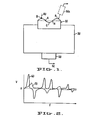
- a relatively thin planar die 20 formed from a silicon or other semiconductor material, is bonded to a relatively massive substrate 30. In order to ensure proper operation, this bond must be both mechanically and thermally satisfactory. In order to evaluate the mechanical bonding of the die to the substrate, the subject method utilizes thermoacoustic detection and/or imaging of the plate-mode patterns of the structure.
- thermoacoustic image is generated by focusing a periodic heat source 40 at a microscopic spot on the surface of the die 20.
- this periodic heating can be supplied by an intensity modulated energy beam defined by, for example, a laser or a stream of particles such as an electron beam.
- an intensity modulated beam 40 is focused on the surface of the die, periodic heating of the sample takes place which causes the generation of thermal waves.
- the thermal waves give rise to acoustic waves that can be detected for example, by a piezoelectric transducer 50.
- various other detectors can be employed to sense the acoustic waves.
- a light detector 50a defines by a laser probe or a laser interferometer, can be utilized.
- the upper surface of the die will exhibit plate-mode or standing wave patterns.
- the standing wave is defined by nodes and antinodes, the latter including both minima and maxima points.
- the nodes (labeled "A") are points on the standing wave which are at zero energy.
- the antinodes include maxima points B, having a high positive energy.
- One antinode minima C is illustrated which represents a point of high energy having an opposite phase as compared with the maxima B.
- a free standing die 20 will generate a standing wave pattern having an intensity which, as discussed above, is dependent on many factors. As illustrated in Figure 1, when the die 20 is bonded to the substrate 30, the combination presents a substantially thicker structure. With all other factors remaining the same, in a securely bonded construction, the intensity of plate-mode resonances will be significantly less than in the free standing situation. Accordingly, by investigating the plate-mode signature of the entire structure, evaluation of the quality of the bond can be made.
- a full thermal-wave or thermoacoustic image is produced. More particularly, after selecting a beam modulation frequency which will produce a plate-mode resonance, the beam 40 is scanned or rastered in a two- dimensional array over the surface of the die. Conversely, the beam can be held stationary and the sample rastered beneath it. The signals 52, sensed by the detector, are used to generate an image of the surface of the die.
- the local acoustic condition on the surface of the die will substantially affect the intensity of the waves which are sensed by detector 50. More particularly, when the beam is located at a node A, only the energy in the beam itself is available to be transmitted to the detector 50. In contrast, significantly more energy is available when the beam is located at antinodes B and C. This result can be explained because the surface of the die is in resonance due to the periodic nature of the energy beam. Since the beam modulation and the plate-mode resonance are at the same frequency, the surface of the die acts as a pump to amplify the energy supplied by the beam. Accordingly, when the beam is located at an antinode, the intensity of the acoustic waves received at the detector will be substantially increased. As the beam is moved between nodes and antinodes, intermediate energy levels will be detected.
- thermoacoustic image of the surface of the die 20 can be generated.
- This image will include the image of the plate-mode resonance pattern for the sample at the beam modulation frequency selected.
- Various methods, including ultrasonic and optical techniques, can be used to generate the thermoacoustic image, some of which are discussed in the previously cited references and therefore need not be described.
- the plate-mode image produced should correspond to a sample having the dimensions of the combination.
- the image produced will tend to approach the image which would result if a free standing die was tested.
- Additional analyses of the bond can be carried out by imaging the plate-mode signature of the structure at other resonant modulation frequencies. As can be appreciated, at different resonant frequencies, the location of the nodes and antinodes of the plate-mode pattern will be at different positions such that more information can be obtained. Plate-mode signatures obtained at different modulation frequencies would be compared to expected signatures at corresponding frequencies.
- the second technique of the subject invention takes advantage of the fact that at different resonant frequencies the location of the nodes and antinodes vary. Accordingly, a significant amount of information can be generated by focusing the beam at a single point and varying the frequency of the modulation of the beam.
- This technique as described more fully immediately below, is particularly suited for mass production situations where a rapid analysis of the integrity of the bond must be made.
- This technique can be readily applied to the manufacture of integrated circuit packages since the substrate 30 typically has a thickness much greater than the die 20 such that the difference in plate-mode signatures of a poorly bonded and a well bonded die is great. Accordingly a reliable evaluation of bond integrity can be obtained without a detailed mode pattern analysis.
- the intensity modulated beam of energy is focused at a single point.
- the frequency of the periodic beam is then varied and the acoustic signals detected are recorded as a function of the modulation frequency.
- Figure 2 an example of the type of output signal which could be sensed by detector 50 is illustrated.
- Figure 2 is a simplified representation for purposes of explanation.
- the Y-axis measures the voltage level sensed by detector 50, while the X-axis measures the change of the modulation frequency over time.
- Curve 60 is intended to represent either a free standing die or a poorly bonded die construction. In this situation, a plurality of intense peaks and valleys are observed which correspond to instances where the beam 4 0 is coincident with antinodal points. As discussed above, when the beam is located on an antinodal point, the energy contained at the surface of the die acts as a pump for increasing the intensity of the acoustic waves.
- Curve 70 is intended to present the situation where the die 20 is securely bonded to the substrate 30. In the latter case, the resonant patterns are significantly damped such that there is little intensity modulation in the detected acoustic signals.
- a predetermined value such as for either the bonded or unbonded condition
- a variety of methods could be used to analyse the signal sensed by detectors 50.
- One relatively simple method would be to rectify and integrate the signal over time.
- the integration of a rectified curve 60 will produce a value far greater than the integration of a rectified curve 70.
- fixed values could be assigned to various quality levels of bonding.
- the accuracy of the assessment of the bond integrity could, of course, be further enhanced by taking successive readings at more than one point on the sample. For example, after the first signals are detected, the beam position can be shifted to a second location to obtain new readings for confirming of enhancing the analysis.
- the method analyses the plate-mode characteristics of the members using thermoacoustic detection and/or imaging.
- the method takes advantage of the fact that the plate-mode signature of a securely bonded combination and a poorly bonded combination will be different.
- the sample is subjected to periodic localized heating to produce thermal waves which in turn produce acoustic waves of a longer wavelength.
- the acoustic waves are detected and processed to obtain the plate-mode signature of the combination.
- the signature which is obtained is compared a predetermined plate-mode signature such as one associated with either a poorly bonded or a securely bonded combination whereby the. integrity of the bond can be assessed.
Landscapes
- Physics & Mathematics (AREA)
- Chemical & Material Sciences (AREA)
- Engineering & Computer Science (AREA)
- Biochemistry (AREA)
- Pathology (AREA)
- Immunology (AREA)
- General Physics & Mathematics (AREA)
- General Health & Medical Sciences (AREA)
- Health & Medical Sciences (AREA)
- Life Sciences & Earth Sciences (AREA)
- Analytical Chemistry (AREA)
- Acoustics & Sound (AREA)
- General Engineering & Computer Science (AREA)
- Multimedia (AREA)
- Optics & Photonics (AREA)
- Mechanical Engineering (AREA)
- Combustion & Propulsion (AREA)
- Mathematical Physics (AREA)
- Investigating Or Analyzing Materials By The Use Of Ultrasonic Waves (AREA)
Applications Claiming Priority (2)
| Application Number | Priority Date | Filing Date | Title |
|---|---|---|---|
| US06/381,891 US4484820A (en) | 1982-05-25 | 1982-05-25 | Method for evaluating the quality of the bond between two members utilizing thermoacoustic microscopy |
| US381891 | 1982-05-25 |
Publications (1)
| Publication Number | Publication Date |
|---|---|
| EP0095227A1 true EP0095227A1 (de) | 1983-11-30 |
Family
ID=23506766
Family Applications (1)
| Application Number | Title | Priority Date | Filing Date |
|---|---|---|---|
| EP83301423A Ceased EP0095227A1 (de) | 1982-05-25 | 1983-03-15 | Verfahren zur Bestimmung der Bindungsqualität zwischen zwei Bauelementen mit Hilfe der thermoakustischen Mikroskopie |
Country Status (4)
| Country | Link |
|---|---|
| US (1) | US4484820A (de) |
| EP (1) | EP0095227A1 (de) |
| JP (1) | JPS58205850A (de) |
| DE (1) | DE95227T1 (de) |
Cited By (5)
| Publication number | Priority date | Publication date | Assignee | Title |
|---|---|---|---|---|
| EP0163466A3 (en) * | 1984-05-21 | 1987-11-04 | Therma-Wave Inc. | Method and apparatus for evaluating both thickness and compositional variables in a layered or thin film sample |
| EP0267727A3 (en) * | 1986-11-06 | 1989-08-30 | Alan Arthur Wells | Gas resonance device |
| EP0368650A1 (de) * | 1988-11-10 | 1990-05-16 | The Haser Company Limited | Gasresonanzvorrichtung |
| WO2011137995A3 (de) * | 2010-05-03 | 2012-05-10 | Fraunhofer-Gesellschaft zur Förderung der angewandten Forschung e.V. | Verfahren und vorrichtung zur messung von verbindungseigenschaften eines werkstoffverbundes |
| EP2487678A1 (de) * | 2011-02-08 | 2012-08-15 | Gehrlein, Jan | Verfahren und Vorrichtung zur Anregung mechanischer Schwingungspulse für Longitudinalwellen und für Transversalwellen |
Families Citing this family (45)
| Publication number | Priority date | Publication date | Assignee | Title |
|---|---|---|---|---|
| JPS59122942A (ja) * | 1982-12-28 | 1984-07-16 | Toshiba Corp | 超音波顕微鏡装置 |
| US4543486A (en) * | 1983-05-20 | 1985-09-24 | The United States Of America As Represented By The Secretary Of The Army | Method and apparatus for using a photoacoustic effect for controlling various processes utilizing laser and ion beams, and the like |
| JPS606860A (ja) * | 1983-06-15 | 1985-01-14 | Hitachi Ltd | 非接触式超音波探傷方法およびその装置 |
| US4752140A (en) * | 1983-12-02 | 1988-06-21 | Canadian Patents And Development Limited/Societe Canadienne Des Brevets Et D'exploitation Limitee | Pulsed dilatometric method and device for the detection of delaminations |
| US4578584A (en) * | 1984-01-23 | 1986-03-25 | International Business Machines Corporation | Thermal wave microscopy using areal infrared detection |
| US4567769A (en) * | 1984-03-08 | 1986-02-04 | Rockwell International Corporation | Contact-free ultrasonic transduction for flaw and acoustic discontinuity detection |
| US4641527A (en) * | 1984-06-04 | 1987-02-10 | Hitachi, Ltd. | Inspection method and apparatus for joint junction states |
| US4710030A (en) * | 1985-05-17 | 1987-12-01 | Bw Brown University Research Foundation | Optical generator and detector of stress pulses |
| US4806292A (en) * | 1986-01-21 | 1989-02-21 | Ford Aerospace & Communications Corporation | System for stabilizing dimensional properties of cured composite structures |
| JPH0827264B2 (ja) * | 1988-09-21 | 1996-03-21 | 工業技術院長 | マルチ変調周波数による光音響撮像方法 |
| US5450752A (en) * | 1989-08-29 | 1995-09-19 | Regents Of The University Of California | Ultrasonic position sensor for measuring movement of an object |
| EP0459392B1 (de) * | 1990-05-30 | 1999-08-18 | Hitachi, Ltd. | Verfahren und Vorrichtung zur Behandlung eines sehr kleinen Bereichs einer Probe |
| JPH04178538A (ja) * | 1990-11-14 | 1992-06-25 | Nippon Steel Corp | 試料内に超音波を発生・検出させる方法及びその装置 |
| JP2717600B2 (ja) * | 1990-11-27 | 1998-02-18 | 新日本製鐵株式会社 | 薄膜評価装置 |
| US5170666A (en) * | 1991-03-29 | 1992-12-15 | Larsen Lawrence E | Nondestructive evaluation of composite materials using acoustic emissions stimulated by absorbed microwave/radiofrequency energy |
| US5344236A (en) * | 1992-01-23 | 1994-09-06 | Fishman Iiya M | Method for evaluation of quality of the interface between layer and substrate |
| US5349813A (en) * | 1992-11-09 | 1994-09-27 | Foster Wheeler Energy Corporation | Vibration of systems comprised of hot and cold components |
| US5698787A (en) * | 1995-04-12 | 1997-12-16 | Mcdonnell Douglas Corporation | Portable laser/ultrasonic method for nondestructive inspection of complex structures |
| US5706094A (en) * | 1995-08-25 | 1998-01-06 | Brown University Research Foundation | Ultrafast optical technique for the characterization of altered materials |
| US6008906A (en) * | 1995-08-25 | 1999-12-28 | Brown University Research Foundation | Optical method for the characterization of the electrical properties of semiconductors and insulating films |
| US5748318A (en) * | 1996-01-23 | 1998-05-05 | Brown University Research Foundation | Optical stress generator and detector |
| US6321601B1 (en) | 1996-08-06 | 2001-11-27 | Brown University Research Foundation | Optical method for the characterization of laterally-patterned samples in integrated circuits |
| US6175416B1 (en) | 1996-08-06 | 2001-01-16 | Brown University Research Foundation | Optical stress generator and detector |
| US5844684A (en) * | 1997-02-28 | 1998-12-01 | Brown University Research Foundation | Optical method for determining the mechanical properties of a material |
| US5713356A (en) * | 1996-10-04 | 1998-02-03 | Optosonics, Inc. | Photoacoustic breast scanner |
| US5748317A (en) * | 1997-01-21 | 1998-05-05 | Brown University Research Foundation | Apparatus and method for characterizing thin film and interfaces using an optical heat generator and detector |
| US5864393A (en) * | 1997-07-30 | 1999-01-26 | Brown University Research Foundation | Optical method for the determination of stress in thin films |
| US6104942A (en) * | 1998-05-12 | 2000-08-15 | Optosonics, Inc. | Thermoacoustic tissue scanner |
| US6038026A (en) * | 1998-07-07 | 2000-03-14 | Brown University Research Foundation | Apparatus and method for the determination of grain size in thin films |
| US6025918A (en) * | 1998-07-07 | 2000-02-15 | Brown University Research Foundation | Apparatus and method for measurement of the mechanical properties and electromigration of thin films |
| US6216025B1 (en) | 1999-02-02 | 2001-04-10 | Optosonics, Inc. | Thermoacoustic computed tomography scanner |
| JP2000261137A (ja) * | 1999-03-12 | 2000-09-22 | Nec Corp | 電子部品接続状態検査装置及び電子部品接続状態検査方法 |
| US6317216B1 (en) | 1999-12-13 | 2001-11-13 | Brown University Research Foundation | Optical method for the determination of grain orientation in films |
| US6466806B1 (en) * | 2000-05-17 | 2002-10-15 | Card Guard Scientific Survival Ltd. | Photoacoustic material analysis |
| SE0100379D0 (sv) * | 2001-02-07 | 2001-02-07 | Siemens Elema Ab | Arrangement for and method of acoustic determination of fluid temperature |
| JP2002272738A (ja) * | 2001-03-21 | 2002-09-24 | Fuji Photo Film Co Ltd | 超音波診断装置 |
| US6490470B1 (en) | 2001-06-19 | 2002-12-03 | Optosonics, Inc. | Thermoacoustic tissue scanner |
| US7357029B2 (en) * | 2004-03-31 | 2008-04-15 | Optometrix, Inc. | Thermal-acoustic scanning systems and methods |
| US7750536B2 (en) | 2006-03-02 | 2010-07-06 | Visualsonics Inc. | High frequency ultrasonic transducer and matching layer comprising cyanoacrylate |
| US8714016B2 (en) * | 2012-02-01 | 2014-05-06 | The Boeing Company | Tension wave generation system |
| CA2942379C (en) | 2014-03-12 | 2021-08-24 | Fujifilm Sonosite, Inc. | High frequency ultrasound transducer having an ultrasonic lens with integral central matching layer |
| JP6371847B2 (ja) * | 2014-06-30 | 2018-08-08 | 富士フイルム株式会社 | 光音響画像生成装置、信号処理装置、及び光音響画像生成方法 |
| US9784668B2 (en) | 2015-05-29 | 2017-10-10 | The Boeing Company | Systems and methods for testing internal bonds |
| US11143628B2 (en) * | 2019-07-15 | 2021-10-12 | The Boeing Company | Joint inspection system and methods of inspecting a joint in a structure |
| WO2024047559A1 (en) * | 2022-08-30 | 2024-03-07 | Technion Research & Development Foundation Limited | A thermoacoustic engine driven by irradiation of an absorbing media or oscillating heating |
Citations (2)
| Publication number | Priority date | Publication date | Assignee | Title |
|---|---|---|---|---|
| WO1980001005A1 (en) * | 1978-11-01 | 1980-05-15 | A Rosencwaig | Photoacoustic or thermoacoustic microscopy |
| EP0019002A1 (de) * | 1978-06-20 | 1980-11-26 | Sumitomo Metal Industries, Ltd. | Verfahren und vorrichtung für den berührungslosen nachweis von fehlern mit hilfe von ultraschall |
Family Cites Families (9)
| Publication number | Priority date | Publication date | Assignee | Title |
|---|---|---|---|---|
| US3008029A (en) * | 1957-06-07 | 1961-11-07 | Gen Dynamics Corp | Means and method for testing of composite sandwich structures |
| US3233450A (en) * | 1961-11-08 | 1966-02-08 | William J Fry | Acoustic flaw detection system |
| US3842663A (en) * | 1972-12-01 | 1974-10-22 | Boeing Co | Demodulated resonance analysis system |
| US4011748A (en) * | 1975-09-18 | 1977-03-15 | The Board Of Trustees Of Leland Stanford Junior University | Method and apparatus for acoustic and optical scanning of an object |
| US4137991A (en) * | 1976-11-23 | 1979-02-06 | International Business Machines Corporation | Clamped acoustic elastic wave generator |
| US4091681A (en) * | 1977-06-21 | 1978-05-30 | The United States Of America As Represented By The Secretary Of The Air Force | Method for the simultaneous determination of low optical bulk and surface absorption coefficients in solids |
| US4218922A (en) * | 1978-09-18 | 1980-08-26 | Battelle Development Corporation | Acoustic inspection of solder joints |
| US4267732A (en) * | 1978-11-29 | 1981-05-19 | Stanford University Board Of Trustees | Acoustic microscope and method |
| US4429578A (en) * | 1982-03-22 | 1984-02-07 | General Electric Company | Acoustical defect detection system |
-
1982
- 1982-05-25 US US06/381,891 patent/US4484820A/en not_active Expired - Fee Related
-
1983
- 1983-03-04 JP JP58034734A patent/JPS58205850A/ja active Pending
- 1983-03-15 DE DE198383301423T patent/DE95227T1/de active Pending
- 1983-03-15 EP EP83301423A patent/EP0095227A1/de not_active Ceased
Patent Citations (2)
| Publication number | Priority date | Publication date | Assignee | Title |
|---|---|---|---|---|
| EP0019002A1 (de) * | 1978-06-20 | 1980-11-26 | Sumitomo Metal Industries, Ltd. | Verfahren und vorrichtung für den berührungslosen nachweis von fehlern mit hilfe von ultraschall |
| WO1980001005A1 (en) * | 1978-11-01 | 1980-05-15 | A Rosencwaig | Photoacoustic or thermoacoustic microscopy |
Non-Patent Citations (4)
| Title |
|---|
| APPLIED PHYSICS LETTERS, vol. 39, no. 5, 1 September 1981 * |
| APPLIED PHYSICS LETTERS, vol. 39, no. 5, 1 September 1981, New York J.-P. MONCHALIN et al. "Thermal contact probing by photoacoustic effect", pages 391-393 * |
| ELECTRONICS INTERNATIONAL, vol. 5,, no. 2, January 1982, New York J. GOSCH "Ultrasonic test uses laser, not transducer", pages 67-68 * |
| PROCEEDINGS OF IEE, vol. 119, no. 2, February 1972 R.M. DE LA RUE et al. "Acoustic-surface-wave amplitude and phase measurements using laser probes", pages 117-125 * |
Cited By (5)
| Publication number | Priority date | Publication date | Assignee | Title |
|---|---|---|---|---|
| EP0163466A3 (en) * | 1984-05-21 | 1987-11-04 | Therma-Wave Inc. | Method and apparatus for evaluating both thickness and compositional variables in a layered or thin film sample |
| EP0267727A3 (en) * | 1986-11-06 | 1989-08-30 | Alan Arthur Wells | Gas resonance device |
| EP0368650A1 (de) * | 1988-11-10 | 1990-05-16 | The Haser Company Limited | Gasresonanzvorrichtung |
| WO2011137995A3 (de) * | 2010-05-03 | 2012-05-10 | Fraunhofer-Gesellschaft zur Förderung der angewandten Forschung e.V. | Verfahren und vorrichtung zur messung von verbindungseigenschaften eines werkstoffverbundes |
| EP2487678A1 (de) * | 2011-02-08 | 2012-08-15 | Gehrlein, Jan | Verfahren und Vorrichtung zur Anregung mechanischer Schwingungspulse für Longitudinalwellen und für Transversalwellen |
Also Published As
| Publication number | Publication date |
|---|---|
| DE95227T1 (de) | 1984-09-27 |
| US4484820A (en) | 1984-11-27 |
| JPS58205850A (ja) | 1983-11-30 |
Similar Documents
| Publication | Publication Date | Title |
|---|---|---|
| US4484820A (en) | Method for evaluating the quality of the bond between two members utilizing thermoacoustic microscopy | |
| EP0150384B1 (de) | Verfahren zur Abbildung einer Wärmewelle | |
| US4679946A (en) | Evaluating both thickness and compositional variables in a thin film sample | |
| EP0162681B1 (de) | Verfahren und Vorrichtung zur Untersuchung der Oberflächenbedingungen einer Probe | |
| US4255971A (en) | Thermoacoustic microscopy | |
| EP0165711B1 (de) | Verfahren und Vorrichtung zum Nachweis von thermischen Wellen | |
| EP0012262B1 (de) | Vorrichtung und Verfahren zur akustischen Prüfung eines mikroskopisch kleinen Teils eines Objekts | |
| US4634290A (en) | Method and apparatus for detecting thermal waves | |
| EP0097473A1 (de) | Bestimmung der Dicke einer Schicht oder Bestimmung der Änderung thermischer Charakteristiken in der Tiefe durch Empfang thermischer Wellen | |
| JPS60203840A (ja) | 光感知材料の無接触非破壊試験のためのマイクロ波測定方法およびマイクロ波測定装置 | |
| Tam et al. | Precise measurements of a magnetostriction coefficient of a thin soft‐magnetic film deposited on a substrate | |
| KR102484671B1 (ko) | 헤테로다인 원자력 현미경 장치, 방법 및 리소그래피 시스템 | |
| Liu et al. | A novel approach for flip chip solder joint quality inspection: Laser ultrasound and interferometric system | |
| Cargill III | Electron‐acoustic microscopy | |
| US4921346A (en) | Tunnel current detecting photo-acoustic spectrometer | |
| Liu et al. | Vibration analysis based modeling and defect recognition for flip-chip solder-joint inspection | |
| Liu et al. | Digital signal processing in a novel flip chip solder joint defects inspection system | |
| US6323484B1 (en) | Method and apparatus for sample current spectroscopy surface measurement | |
| Love et al. | Acoustic microscopy of ceramic capacitors | |
| Liu et al. | A novel method and device for solder joint quality inspection by using laser ultrasound | |
| EP0721101A2 (de) | Verfahren und Vorrichtung zur Identifizierung und Charakterisierung eines Materials | |
| US4967150A (en) | Method and apparatus for phase measurement of signals at a measuring point by an unmodulated particle beam | |
| Or et al. | Sensors for automatic process control of wire bonding | |
| Reddy et al. | Non-destructive failure analysis of various chip to package interaction anomalies in FCBGA packages subjected to temperature cycle reliability testing | |
| JP3080158B2 (ja) | プリント基板の検査方法及び検査装置 |
Legal Events
| Date | Code | Title | Description |
|---|---|---|---|
| PUAI | Public reference made under article 153(3) epc to a published international application that has entered the european phase |
Free format text: ORIGINAL CODE: 0009012 |
|
| AK | Designated contracting states |
Designated state(s): DE FR GB NL |
|
| EL | Fr: translation of claims filed | ||
| TCNL | Nl: translation of patent claims filed | ||
| 17P | Request for examination filed |
Effective date: 19840517 |
|
| DET | De: translation of patent claims | ||
| STAA | Information on the status of an ep patent application or granted ep patent |
Free format text: STATUS: THE APPLICATION HAS BEEN REFUSED |
|
| 18R | Application refused |
Effective date: 19870122 |
|
| RIN1 | Information on inventor provided before grant (corrected) |
Inventor name: ROSENCWAIG, ALLAN |