EP0095232A2 - Dispositif de traitement au jet abrasif monté à l'intérieur d'un récipient transportable - Google Patents
Dispositif de traitement au jet abrasif monté à l'intérieur d'un récipient transportable Download PDFInfo
- Publication number
- EP0095232A2 EP0095232A2 EP83301709A EP83301709A EP0095232A2 EP 0095232 A2 EP0095232 A2 EP 0095232A2 EP 83301709 A EP83301709 A EP 83301709A EP 83301709 A EP83301709 A EP 83301709A EP 0095232 A2 EP0095232 A2 EP 0095232A2
- Authority
- EP
- European Patent Office
- Prior art keywords
- shot blasting
- container
- machinery
- shot
- blasting machinery
- Prior art date
- Legal status (The legal status is an assumption and is not a legal conclusion. Google has not performed a legal analysis and makes no representation as to the accuracy of the status listed.)
- Withdrawn
Links
Images

Classifications
-
- B—PERFORMING OPERATIONS; TRANSPORTING
- B24—GRINDING; POLISHING
- B24C—ABRASIVE OR RELATED BLASTING WITH PARTICULATE MATERIAL
- B24C3/00—Abrasive blasting machines or devices; Plants
- B24C3/02—Abrasive blasting machines or devices; Plants characterised by the arrangement of the component assemblies with respect to each other
- B24C3/06—Abrasive blasting machines or devices; Plants characterised by the arrangement of the component assemblies with respect to each other movable; portable
Definitions
- This invention relates to shot blasting machinery, and it is an object of the present invention to provide shot blasting machinery which is easily and readily transportable between sites whereat shot blast cleaning is to be effected.
- shot blasting machinery housed within a transportable container having predetermined areas of the sheeting which constitute the walls of the container removable to permit a workpiece to be conveyed past a shot blasting wheel of the machinery.
- the container is transportable, lying on its side, between sites on a trailer vehicle or other transporter and is disposed upright usually off the trailer or other transporter and on the ground for shot blast cleaning purposes.
- the container corner lifting points are employed for moving the container between the trailer or other transporter and ground.
- the container corner blocks are preferably employed to fix the container to the site floor for shot blast cleaning purposes.
- the shot blast machinery is preferably built onto the end of the container which constitutes the base structure when the antainer is disposed upright.
- the skeletal framework being built up from the base structure around the shot blading machinery, and the framework being infilled with fixed and removable sheeting to define the container walls.
- Wear plates are preferably inset in the walls of the blasting cabinet of the shot blasting machinery at required locations.
- the transportable container and shot blasting machinery assembly is preferably a welded structure.
- the shot blasting machinery preferably comprises a blast cabinet through which a workpiece can be conveyed, at least one reversible shot blasting wheel assembly, an abrasive storage hopper from which abrasive can be fed to the wheel assembly via a control valve, at least one conveyor screw for collecting spent abrasive and debris from the workpiece and delivering same to at least one bucket elevator which, in turn, delivers same to at least one separator from which dean shot is returned to the storage hopper.
- the separator is preferably an air wash separator having associated with it a heavy dust hopper which is adapted to discharge to the floor of the container and a dust extraction box to which a dust collector can be connected by flexible ducting.
- the transportable container 10 is built to standard container dimensions and has the usual corner lifting points.
- the shot blasting machinery which will be described shortly, is built onto an end wall 11 of the container, which end wall 11 constitutes the base of the assembly when the latter is free standing on a site floor for shot blast cleaning purposes.
- the container corner blocks are used temporarily to fix the container 10 to the site floor.
- a skeletal rectangular framework 12 is erected around the machinery and this framework 12 is then infilled with fixed and removable sheeting which defines the walls of the container 10.
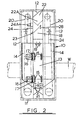
- this embodiment comprises a shot blasting cabinet 13 with wear plates (not shown) on its walls and with a vestibule 14 fitted to each of two opposed sides thereof.
- Each throwing wheel 15 and its motor 16 is mounted on a door 17 hinged to the blasting cabinet 13 so that access can be gained for maintenance purposes. It will be manifest, therefore, that. the sheeting constituting the container walls is removable in the area of these doors,17.
- Each pair of vertically-spaced throwing wheels 15 is fed with abrasive from one of a pair of storage hoppers 18 via manually operable control valves 19 and piping (not shown).
- Each storage hopper 18 has an overflow pipe (not shown) for balancing purposes between the hoppers.
- Each vestibule 14 has disposed at a different side thereof a bucket elevator 20, each of which delivers spent abrasive and debris from a corresponding delivery screw 21 in the base of the blasting cabinet 13 to a corresponding airwash separator 22.
- Clean shot is delivered from each separator 22 to its corresponding storage hopper 18 while heavy dust passes to a corresponding heavy dust hopper 23 dischargeable to the container floor.
- Each separator 22 has associated with it a dust extraction box 22A linked to a dust extraction box 24 for the cabinet 13 and a dust collector (not shown) can be connected to these at 24A by ducting (also not shown).
- ducting also not shown.
- the sheeting will be removable to permit securement to the ducting.
- a workpiece conveyor 25 passes through the blasting cabinet 13 and vestibules, 14 and, of course, sheeting at opposed sides of the cabinet 10 in this area is removable for passage of the workpiece W.
- a pair of seal plates 26 are fitted at both ends of the workpiece passage to contain abrasive and dust and debris.
- the machinery control panel is arranged so that when the container is laid on a trailer 27 the control panel is disposed on one of the major vertical faces of the container 10.
- the container 10 When not in use the container 10 has closed walls and can be conveyed between sites on the trailer 27. On reaching a site where work is to be done the container 10 is laid upright on the ground and is secured to the site floor.
- Sheeting is removed to permit passage of the workpieces to be cleaned and the appropriately profiled seal plates 26 fitted.
- the operator supplies the storage hoppers 18 with abrasive, opens the control valves 19 and starts up the machinery, workpieces being passed through the machinery until the job has been completed.
- a gate 28 is then moved from the position shown in full lines in Fig. 2 to the position shown in dotted lines and the machinery run so that all abrasive is delivered via the heavy dust hoppers 23 onto the container floor from whence it is removed.
Landscapes
- Engineering & Computer Science (AREA)
- Mechanical Engineering (AREA)
- Filling Or Emptying Of Bunkers, Hoppers, And Tanks (AREA)
- Loading Or Unloading Of Vehicles (AREA)
- Refuse Collection And Transfer (AREA)
- Cleaning In General (AREA)
Applications Claiming Priority (2)
| Application Number | Priority Date | Filing Date | Title |
|---|---|---|---|
| GB8214996 | 1982-05-22 | ||
| GB8214996 | 1982-05-22 |
Publications (2)
| Publication Number | Publication Date |
|---|---|
| EP0095232A2 true EP0095232A2 (fr) | 1983-11-30 |
| EP0095232A3 EP0095232A3 (fr) | 1985-10-09 |
Family
ID=10530557
Family Applications (1)
| Application Number | Title | Priority Date | Filing Date |
|---|---|---|---|
| EP83301709A Withdrawn EP0095232A3 (fr) | 1982-05-22 | 1983-03-25 | Dispositif de traitement au jet abrasif monté à l'intérieur d'un récipient transportable |
Country Status (2)
| Country | Link |
|---|---|
| EP (1) | EP0095232A3 (fr) |
| GB (1) | GB2122120B (fr) |
Cited By (10)
| Publication number | Priority date | Publication date | Assignee | Title |
|---|---|---|---|---|
| EP0179596A3 (fr) * | 1984-10-16 | 1987-05-20 | RAMCO OIL SERVICES plc | Installation pour le revêtement de tuyaux, éléments tubulaires et analogues |
| GB2179720B (en) * | 1985-08-31 | 1989-03-01 | Gewerk Eisenhuette Westfalia | Mobile apparatus for cleaning remnants of carbon blocks |
| WO1992008234A1 (fr) * | 1990-10-30 | 1992-05-14 | Tti Engineering, Inc. | Systeme mobile de decontamination par bombardement au co¿2? |
| US5481832A (en) * | 1993-09-23 | 1996-01-09 | Tirikos; Steven M. | Bridge sand blasting support apparatus |
| WO2000074895A1 (fr) * | 1999-06-08 | 2000-12-14 | Danieli & C. Officine Meccaniche S.P.A. | Procede de construction d'installations industrielles |
| CN107443257A (zh) * | 2016-05-30 | 2017-12-08 | 哈尔滨显著科技有限公司 | 一种大径圆筒双抛头内壁抛丸机 |
| CN112223124A (zh) * | 2020-11-19 | 2021-01-15 | 浙江金洲管道工业有限公司 | 一种大口径钢管内壁自密封内循环抛丸除锈装置 |
| CN113084715A (zh) * | 2021-04-24 | 2021-07-09 | 宫礼康 | 一种钢管内壁除锈机、除锈方法及其除锈机构和侧板 |
| CN116512137A (zh) * | 2023-05-15 | 2023-08-01 | 长春理工大学 | 一种用于轴承内圈表面磨粒流加工的设备 |
| CN117984239A (zh) * | 2024-01-17 | 2024-05-07 | 大丰市申达机械制造有限公司 | 一种多抛式高效抛丸机 |
Families Citing this family (2)
| Publication number | Priority date | Publication date | Assignee | Title |
|---|---|---|---|---|
| GB8304919D0 (en) * | 1983-02-22 | 1983-03-23 | Potts M | Apparatus for shot blasting |
| CN114102447B (zh) * | 2021-11-05 | 2023-10-10 | 江苏三迪机车制造有限公司 | 一种具有全方位多角度喷砂结构的抛丸设备及使用方法 |
Family Cites Families (4)
| Publication number | Priority date | Publication date | Assignee | Title |
|---|---|---|---|---|
| US2869291A (en) * | 1955-05-03 | 1959-01-20 | Michael Abraham | Shot blasting machines |
| US3399492A (en) * | 1966-07-21 | 1968-09-03 | C H Heist Ohio Corp | Sandblast truck assembly |
| US3559343A (en) * | 1968-07-05 | 1971-02-02 | Heist Corp C H | Sandblast truck |
| US4019284A (en) * | 1975-07-07 | 1977-04-26 | Hileman Jr Fred Lee | Self-contained sandblasting apparatus |
-
1983
- 1983-03-25 EP EP83301709A patent/EP0095232A3/fr not_active Withdrawn
- 1983-03-25 GB GB08308345A patent/GB2122120B/en not_active Expired
Cited By (11)
| Publication number | Priority date | Publication date | Assignee | Title |
|---|---|---|---|---|
| EP0179596A3 (fr) * | 1984-10-16 | 1987-05-20 | RAMCO OIL SERVICES plc | Installation pour le revêtement de tuyaux, éléments tubulaires et analogues |
| GB2179720B (en) * | 1985-08-31 | 1989-03-01 | Gewerk Eisenhuette Westfalia | Mobile apparatus for cleaning remnants of carbon blocks |
| WO1992008234A1 (fr) * | 1990-10-30 | 1992-05-14 | Tti Engineering, Inc. | Systeme mobile de decontamination par bombardement au co¿2? |
| US5481832A (en) * | 1993-09-23 | 1996-01-09 | Tirikos; Steven M. | Bridge sand blasting support apparatus |
| WO2000074895A1 (fr) * | 1999-06-08 | 2000-12-14 | Danieli & C. Officine Meccaniche S.P.A. | Procede de construction d'installations industrielles |
| CN107443257A (zh) * | 2016-05-30 | 2017-12-08 | 哈尔滨显著科技有限公司 | 一种大径圆筒双抛头内壁抛丸机 |
| CN107443257B (zh) * | 2016-05-30 | 2024-02-09 | 哈尔滨显著科技有限公司 | 一种大径圆筒双抛头内壁抛丸机 |
| CN112223124A (zh) * | 2020-11-19 | 2021-01-15 | 浙江金洲管道工业有限公司 | 一种大口径钢管内壁自密封内循环抛丸除锈装置 |
| CN113084715A (zh) * | 2021-04-24 | 2021-07-09 | 宫礼康 | 一种钢管内壁除锈机、除锈方法及其除锈机构和侧板 |
| CN116512137A (zh) * | 2023-05-15 | 2023-08-01 | 长春理工大学 | 一种用于轴承内圈表面磨粒流加工的设备 |
| CN117984239A (zh) * | 2024-01-17 | 2024-05-07 | 大丰市申达机械制造有限公司 | 一种多抛式高效抛丸机 |
Also Published As
| Publication number | Publication date |
|---|---|
| EP0095232A3 (fr) | 1985-10-09 |
| GB2122120A (en) | 1984-01-11 |
| GB2122120B (en) | 1985-07-31 |
| GB8308345D0 (en) | 1983-05-05 |
Similar Documents
| Publication | Publication Date | Title |
|---|---|---|
| EP0095232A2 (fr) | Dispositif de traitement au jet abrasif monté à l'intérieur d'un récipient transportable | |
| US4096300A (en) | Process of coating a series of metal members | |
| US5417301A (en) | Environmentally safe work platform | |
| US4603516A (en) | Self propelled pipe blast cleaner capable of travel along a pipeline supported over the ditch | |
| US4326362A (en) | Shot blast machine | |
| EP1480867B1 (fr) | Usine de montage servant au montage de produits industriels | |
| US4508211A (en) | Reciprocating floor conveyor apparatus and method | |
| US5233796A (en) | Mobile containerized sandblasting multi-unit | |
| EP0968914B1 (fr) | Dispositif et méthode pour travailler les surfaces intérieures des cales d'un bateau | |
| US5807168A (en) | Self-contained device for cleaning and coating hold surfaces in a bulk carrier | |
| JP2008516122A (ja) | 破砕石、砂利及び他の材料を輸送する軌道台車用タンク、特に鉄道バラスト復旧機用タンク、前記タンクを含む鉄道バラスト復旧機用台車、及び前記台車を得るための方法 | |
| WO1983004014A1 (fr) | Dispositif de levage actionne mecaniquement, possedant une structure de colonne d'acier permettant de lever et de deplacer avantageusement des conteneurs de serie 1, des vehicules et des objets lourds | |
| US5542495A (en) | Bridge cleaner and paint/debris holder apparatus | |
| US2810336A (en) | Apparatus for finishing surfaces of articles | |
| CN214080951U (zh) | 一种火车缓冲器箱体自动喷砂除锈机 | |
| US5302004A (en) | Method of removing asbestos from a building | |
| DE102021128813A1 (de) | Verfahren zur Herstellung von Rohbauten für einen Kraftwagen sowie Fertigungsanlage | |
| US2924912A (en) | Blast treatment apparatus | |
| CN115771784A (zh) | 翻车机集装箱余料清扫系统及方法 | |
| CN209814039U (zh) | 一种建筑工程用多功能搬运机 | |
| US3613204A (en) | Overall processing of structural members | |
| US2440379A (en) | Transport vehicle | |
| US6186272B1 (en) | Trailer for painting | |
| US2465360A (en) | Abrasive cleaning system | |
| CN223618736U (zh) | 一种动车组加砂设备 |
Legal Events
| Date | Code | Title | Description |
|---|---|---|---|
| PUAI | Public reference made under article 153(3) epc to a published international application that has entered the european phase |
Free format text: ORIGINAL CODE: 0009012 |
|
| AK | Designated contracting states |
Designated state(s): AT BE CH DE FR IT LI NL SE |
|
| PUAL | Search report despatched |
Free format text: ORIGINAL CODE: 0009013 |
|
| AK | Designated contracting states |
Designated state(s): AT BE CH DE FR IT LI NL SE |
|
| STAA | Information on the status of an ep patent application or granted ep patent |
Free format text: STATUS: THE APPLICATION IS DEEMED TO BE WITHDRAWN |
|
| 18D | Application deemed to be withdrawn |
Effective date: 19860610 |
|
| RIN1 | Information on inventor provided before grant (corrected) |
Inventor name: PRYKE, LAWSON DEREK |