EP0095264A2 - Accouplements flexibles - Google Patents
Accouplements flexibles Download PDFInfo
- Publication number
- EP0095264A2 EP0095264A2 EP83302523A EP83302523A EP0095264A2 EP 0095264 A2 EP0095264 A2 EP 0095264A2 EP 83302523 A EP83302523 A EP 83302523A EP 83302523 A EP83302523 A EP 83302523A EP 0095264 A2 EP0095264 A2 EP 0095264A2
- Authority
- EP
- European Patent Office
- Prior art keywords
- coupling
- flexible
- torque
- counter
- elements
- Prior art date
- Legal status (The legal status is an assumption and is not a legal conclusion. Google has not performed a legal analysis and makes no representation as to the accuracy of the status listed.)
- Granted
Links
Images


Classifications
-
- F—MECHANICAL ENGINEERING; LIGHTING; HEATING; WEAPONS; BLASTING
- F16—ENGINEERING ELEMENTS AND UNITS; GENERAL MEASURES FOR PRODUCING AND MAINTAINING EFFECTIVE FUNCTIONING OF MACHINES OR INSTALLATIONS; THERMAL INSULATION IN GENERAL
- F16D—COUPLINGS FOR TRANSMITTING ROTATION; CLUTCHES; BRAKES
- F16D3/00—Yielding couplings, i.e. with means permitting movement between the connected parts during the drive
- F16D3/50—Yielding couplings, i.e. with means permitting movement between the connected parts during the drive with the coupling parts connected by one or more intermediate members
- F16D3/72—Yielding couplings, i.e. with means permitting movement between the connected parts during the drive with the coupling parts connected by one or more intermediate members with axially-spaced attachments to the coupling parts
-
- F—MECHANICAL ENGINEERING; LIGHTING; HEATING; WEAPONS; BLASTING
- F16—ENGINEERING ELEMENTS AND UNITS; GENERAL MEASURES FOR PRODUCING AND MAINTAINING EFFECTIVE FUNCTIONING OF MACHINES OR INSTALLATIONS; THERMAL INSULATION IN GENERAL
- F16D—COUPLINGS FOR TRANSMITTING ROTATION; CLUTCHES; BRAKES
- F16D3/00—Yielding couplings, i.e. with means permitting movement between the connected parts during the drive
- F16D3/50—Yielding couplings, i.e. with means permitting movement between the connected parts during the drive with the coupling parts connected by one or more intermediate members
- F16D3/60—Yielding couplings, i.e. with means permitting movement between the connected parts during the drive with the coupling parts connected by one or more intermediate members comprising pushing or pulling links attached to both parts
Definitions
- This invention relates to flexible couplings.
- Our British Patent No. 1441247 describes such a coupling the purpose of which is to transmit a mean torque from one rotating shaft to another but not to transmit fluctuations in that torque should they occur.
- This coupling comprises input and out put members respectively connectibel to rotary driving and driven shafts and interconnected by flexible elements which are deformable in the plane of rotation by torque transmitted through the coupling and by centrifugal force acting on the coupling elements such that over a range of speeds of rotation of the coupling and torques transmitted by the coupling one member is relatively rotatable with respect to the other.
- British Patent No. 1226943 also discloses such a coupling.
- the ratio of the torsional stiffness of a coupling to a mean torque being transmitted at any time (referred to as the "S/T ratio") has a Low value, then, if the one part of the rotating system be subjected to torque fluctuations of a given value above and below the mean value, the value of the torque fluctuations transmitted through the coupling to the other part of the system will be almost directly proportional to the S/T ratio. Thus, if the S/T ratio at the time, speed, and mean torque considered be zero, there will be no transmitted torque fluctuations, irrespective of the fluctuations on the transmitting side. If on the other hand the S/T ratio has a retlatively high value - say 50 or more - the coupling will have LittLe effect in reducing the transitted fluctuations.
- the coupling will transmit a proportion of the fluctuations imposed on it.
- the coupling characteristics of the coupting described in our Patent No. 1441247 are such that it maintains a minimum S/T ratio whilst running along its design power/speed Line which equates to the well known power cube Law retation- ship.
- the design Line can be varied by altering the geometrical structure of the coupling, but, deviation from this Line at a given speed will result in an increase in S/T ratio. This ratio will remain Low i.e. below 10 for a range of torques at any given speed.
- the invention provides a coupling which has an S/T ratio which is Low over a wider range of torques and speeds than has hitherto been thought possible with existing couplings.
- ALternativeLy the invention provides a coupling which has Lower S/T ratios, over a comparable torque and speed range, than has hitherto been thought possible with existing couplings.
- This object is achieved by disposing a spacer concentrically between the input and out members and which is connected to each member by said coupling elements such that over a Larger range of torques and speeds the spacer is relatively rotatable with respect to at least one member.
- each coupling unit has the same range of torques and speeds for a given S/T ratio then the combined coupling will have, at any given speed and torque, a smaller S/T ratio than either individual coupling unit at that speed and torque. This also means of course that for the same S/T ratios wider Limits of torque and speed can be accommodated by the coupling.
- the present invention also permits variations and additions to the basic design. For instance it is feasible to include counter centrifugal means in one or both coupling units to counter the effect of centrifugal force on the coupling elements and thus to bias them towards a position which they would adopt when the coupling was at rest. This gives the coupling a degree of rigidity at aLL speeds and hence prevents or at Least subdues the effects of backlash.
- the coupling elements may each comprise two Links pivoted to one another in the plane of rotation and at their other ends to one member and the spacer respectively.
- Each coupling unit has no LateraL rigidity however and hence to put the invention into effect, the spacer must be laterally, that is to say, radially supported.
- a flexible coupling characterised in that it includes a secondary coupling between the input and out put members and which is substantially radially rigid. PreferabLy said secondary coupling is also rotationally free.
- two such couplings according to this second aspect of the invention may be joined in series to form a coupling according to the first aspect of the invention without the necessity of any further radial support for the spacer formed by the output member of the first coupling being joined to the input member of the second.
- the coupling according to the second aspect of this invention can also be used in conjunction with other couplings which may be angularly flexible and which could not normally be used with couplings according to the invention unless radial support was provided for the spacer between them.
- said secondary coupling comprises a bearing disposed between axial interjacent flanges of each member.
- Such a coupling arrangement may be constructed so as to have a certain amount of Loose radial play whereby the coupling can accept a small amount of LateraL misalignment between the members before the whole coupling becomes radially stiff thus preventing further radial misalignment.
- the secondary coupling may also be axially rigid.
- the secondary coupling is a bearing disposed between axial interjacent flanges of each member the bearing is preferably a thrust bearing.
- a coupling according to the second aspect of this invention has a secondary coupling which is axially free so as to allow such expansion,
- the coupling elements must be capable of accepting axial movement and coupling elements which would satisfy this criterion are disclosed in our European PubLished Patent Application No. 34,440.
- the bearing may be in the form of a ball race bearing or in the form of a plain bearing.
- the coupling is to be axially rigid either bearing can be arranged with spherical seats to absorb and counteract axial thrusts. Where spherical seats are provided, although the resultant coupling is axially rigid it is nevertheless capable of accepting a degree of angular misalignment between the two members.
- the resultant coupling can accept a net LateraL misalignment between the two shafts since each coupling unit is able to misalignment. CLearLy the Longer the spacer between the input and output members the greater amount of LateraL misalignmentwhich can be accommodated between the shafts.
- An alternative embodiment provides a secondary coupling which comprises a cross Link flexural pivot coupling which is radially stiff and which within Limits is rotationally free. Such a secondary coupling may however provide counter torque means for the coupling.
- Figs.1a and 1b show a coupling 10 comprising an input member 11 and an output member 12 connected to respective shafts 16,18.
- the shaft 16 is, in this coupling 10, the driving shaft and it drives in the direction of the Arrow R in Fig.lb.
- the two members 11,12 are interconnected by a plurality of coupling elements 1,2,3 which each comprise a pair of Links 4,5 pivotally interconnected at point J.
- the Links 4,5 are pivotally connected to the members 11,12 at respective points X,Y.
- Fig.2 a number of relative rotational positions of the members 11,12 are shown (the member 12 being taken as stationary) and the resultant positions of the Links 4,5.
- the member 11 is rotated in a clockwise direction in the drawing relative to the member 12, thus representing the effect of centrifugal force, from a position where the point X is at X 1 to the point where X is at X 4
- the pivot point J between the Links 4,5 describes an arc from J 1 to J 4 around centre Y.
- the Links may be free to move between any of the positions X 1 ,J 1 , to X 4 ,J 4 , but in another coupling counter torque means are provided to bias the Links towards the position X 1 ,J 1 ,Y.
- centrifugal force C.F. acts on the Links 4,5, effectively at pivot J tending to throw them away from centre 0 and towards the position X 2 ,J 2 ,Y.
- the centrifugal force applies forces P X ,P Y along the Links 4,5 respectively and towards the point J.
- the forces P X ,P Y in the Links 4,5 apply torques to the members 11,12 equal and opposite to the torque T.
- the turning moment T about centre 0 of the member 12 is given by the product of R T , the radius of application of the force P Y about centre 0, and the force Py.
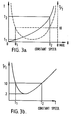
- Fig.3a The torque characteristics of a given coupling are shown in Fig.3a in which the Torque T across the coupling is plotted against the deflection 8 of the coupling at a given constant speed above zero.
- Fig.4 shows a coupling in accordance with the first aspect of the present invention.
- the coupling comprises two coupling units A,B of the type described with reference to Figs.1 to 3 joined together via a spacer 60.
- Each coupling unit A or B comprises members 11 and 12 which are interconnected by coupling elements 1 (only one of which can be seen).
- Fig.5 is a plot of S/T ratios versus torque transmitted for the coupling of Fig.4.
- Line A represents the curve for the coupling A acting individually while
- Line B represents that for coupling 8 acting individually.
- the curve (A+B) shows the S/T ratio at speed V for various torques of the compound coupling A,60,B.
- this curve is not a mean curve for A or B, nor even simply the sum of the two but is in fact even better than that.
- a possibly reasonable comparison may be made with springs but even these do not show the same characteristics.
- PLotting (S/T) (A+B) on the graph in Fig.5 we find it stays below the curves of A and B, and in this instance stays below the nominal S/T value of 10 from torque T (A+B)1 , which is Less than T A1 , to torque T (A+B)2 , which is greater than T B2 . That is to say, the resultant coupling can accommodate torques over a range not only greater than one or other of the two couplings but in fact over a range greater than the sum of the ranges of the two individual couplings. Moreover, within the range TA1 to TB2 the resultant compound coupling is significantly softer - i.e. has smaller S/T ratios - than either individual coupling.
- Fig.6 illustrates the complete characteristics of a given coupling.
- the speed V of the coupling is plotted against the torque T transmitted by the coupling.
- the coupling will have a given S/T ratio and the curves on the graph represent Lines of equal S/T ratio.
- the solid Line represents that set of values of torque T and speed V at which the coupling has its lowest S/T ratio, which in this case is 2.
- dotted Lines represent S/T ratios equal to 4 and so on.
- a similar graph can be plotted for the coupling B only for this coupling the speeds and torques at which the S/T ratio is the minimum, say 2 again, are different to those for the coupling A.
- ALso as the speed increases or decreases for a given torque from any point on the solid Line, or as the torque increases or decreases for a given speed from any point on that line, the S/T ratio increases. It increases slowly at first but then exponentially. Thus at any speed V x and any torque T X it is possible to approximate the S/T ratio of each coupling.
- the second aspect of this invention provides coupling units which have LateraL or radial rigidity and hence can simply be joined in series in accordance with the first aspect of the invention.
- the members 11 and 12 have interjacent axial flanges 21 and 22 respectively which support therebetween means for imparting lateral rigidity between the two members 11 and 12.
- Fig.7a these means comprise a ball bearing assembly 24 which has an outer race 26 mounted internally of the flange 22 and an inner race 28 mounted externally of the flange 21.
- BaLLs 30 are disposed between the races 26,28.
- Fig.7b these means comprise a bearing assembly 34 having bearing seats 36,38 disposed internally of the flange 22 and externally of the flange 21 respectively. These seats 36,38 have Low friction surfaces.
- the respective seats 26,28 and 36,38 are spherically arranged for two reasons.
- FirstLy because the arrangement can then accept a certain amount of angular misalignment between the two members 11 and 12; at Least as much as the coupling element 1 can accept (even when this element is as described in European PubLished AppLication No. 34,440).
- SecondLy these bearings can serve as thrust bearings and so absorb any residual axial thrust between the members 11,12 which may arise.
- Fig.7c a slightly different arrangement to that of Fig.7a is shown.
- the flange 21 comprises a plurality of rods or the Like attached to the member 11 and which carry individual bearings 44 arranged to roll inside the flange 22. At Least three of such bearings 44 arranged circumferentially inside the flange 22 would provide an adequate degree of LateraL rigidity in all directions.
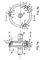
- Figs.8a and 8b illustrate the use of a cross Link flexural pivot coupling 50 to provide the radial rigidity for the members 11 and 12.
- the pivot coupling 50 comprises the two members 11,12 having tube sections 18,19 respectively and between which are disposed the coupling elements 1,2,3 as in previous embodiments.
- the members 11,12 have respective interdigitating flanges 21,22.
- DiametricaLLy between the flange 21 and member 12 is disposed a cross-Link 51.
- another cross-Link 52 is also disposed but preferably at right angles to the first cross-link 51 as can be seen from Fig.7.
- the combined coupling A,60,B is in fact two couplings of the type described above with reference to Fig.7a connected together by torque tube 60. Because the couplings A,B can each accept a certain degree of angular misalignment, the resultant compound coupling A,60,B can then accept a LateraL misalignment between the shafts connected to the members 11,11a. This is schematically illustrated in Fig.4a where two shafts 62,64 are LateraLLy misaligned by 0-0'. The two couplings A and B, together with the torque tube 60, allow these two shafts to be connected. CLearLy the Longer the torque tube 60 is, the greater the misalignment between the shafts 62,64 which the compound coupling A,60,B is capable of accepting.
Landscapes
- Engineering & Computer Science (AREA)
- General Engineering & Computer Science (AREA)
- Mechanical Engineering (AREA)
- Mechanical Operated Clutches (AREA)
- Transmission Devices (AREA)
- Materials For Medical Uses (AREA)
Applications Claiming Priority (2)
| Application Number | Priority Date | Filing Date | Title |
|---|---|---|---|
| GB8214807 | 1982-05-21 | ||
| GB8214807 | 1982-05-21 |
Publications (3)
| Publication Number | Publication Date |
|---|---|
| EP0095264A2 true EP0095264A2 (fr) | 1983-11-30 |
| EP0095264A3 EP0095264A3 (en) | 1984-07-25 |
| EP0095264B1 EP0095264B1 (fr) | 1988-08-17 |
Family
ID=10530513
Family Applications (1)
| Application Number | Title | Priority Date | Filing Date |
|---|---|---|---|
| EP83302523A Expired EP0095264B1 (fr) | 1982-05-21 | 1983-05-05 | Accouplements flexibles |
Country Status (10)
| Country | Link |
|---|---|
| US (1) | US4575357A (fr) |
| EP (1) | EP0095264B1 (fr) |
| JP (1) | JPS58211021A (fr) |
| AU (1) | AU564465B2 (fr) |
| CA (1) | CA1209818A (fr) |
| DE (1) | DE3377735D1 (fr) |
| ES (1) | ES522594A0 (fr) |
| GB (1) | GB2120749B (fr) |
| MX (1) | MX155951A (fr) |
| ZA (1) | ZA832981B (fr) |
Cited By (4)
| Publication number | Priority date | Publication date | Assignee | Title |
|---|---|---|---|---|
| WO1986004653A1 (fr) * | 1985-02-05 | 1986-08-14 | Flexibox Limited | Ameliorations aux accouplements centrifuges |
| EP0462356A1 (fr) * | 1990-06-09 | 1991-12-27 | Firma Carl Freudenberg | Accouplement élastique rotatif |
| WO2007112978A1 (fr) | 2006-03-31 | 2007-10-11 | Martin Buchholz | Procede de conversion d'energie dans une installation thermique de maintien de la temperature d'un batiment, et dispositif |
| CN112253648A (zh) * | 2014-08-05 | 2021-01-22 | 科特雷恩控股有限公司 | 一比一扭矩联轴器 |
Families Citing this family (1)
| Publication number | Priority date | Publication date | Assignee | Title |
|---|---|---|---|---|
| US6033285A (en) * | 1998-02-06 | 2000-03-07 | Marvel Enterprises, Inc. | Vibrating toy car with special effects |
Family Cites Families (26)
| Publication number | Priority date | Publication date | Assignee | Title |
|---|---|---|---|---|
| GB573709A (fr) * | ||||
| GB240259A (en) * | 1924-02-14 | 1925-10-01 | Det Tekniske Forsogsktieselska | Improvements in yielding shaft-couplings |
| BE346473A (fr) * | 1926-12-08 | |||
| US1685158A (en) * | 1927-11-21 | 1928-09-25 | Weber Engine Company | Coupling |
| US2551837A (en) * | 1948-09-15 | 1951-05-08 | Falk Corp | End thrust and torque transmitting coupling |
| GB731814A (en) * | 1952-01-25 | 1955-06-15 | Compression Ignition Ltd | Improvements in or relating to flexible couplings |
| GB795640A (en) * | 1955-09-30 | 1958-05-28 | Bendix Aviat Corp | Shaft couplings |
| GB840682A (en) * | 1957-06-04 | 1960-07-06 | Twiflex Couplings | Improvements in or relating to torsionally resilient couplings |
| FR1177883A (fr) * | 1957-06-19 | 1959-04-30 | Joint homocinétique | |
| GB939074A (en) * | 1961-04-19 | 1963-10-09 | Twiflex Couplings | Improvements in or relating to torsional vibration dampers |
| GB975547A (en) * | 1962-11-06 | 1964-11-18 | Charles Wallace Chapman | Improvements in or relating to couplings for transmitting a drive between rotatable driving and driven members |
| JPS422005Y1 (fr) * | 1965-01-18 | 1967-02-07 | ||
| GB1226943A (fr) * | 1967-04-05 | 1971-03-31 | ||
| US3481158A (en) * | 1968-07-22 | 1969-12-02 | Kaman Corp | Flexible coupling |
| GB1294691A (en) * | 1969-01-03 | 1972-11-01 | Twiflex Couplings | Improvements in rotatable couplings |
| AT303466B (de) * | 1970-04-27 | 1972-11-27 | Leonhard Geislinger Dr Ing | Biegeelastische Kupplung |
| DE2100052B2 (de) * | 1971-01-02 | 1975-07-31 | Atec Antriebstechnik-Weiss Kg, 4000 Duesseldorf | Elastische Kupplung |
| US3739600A (en) * | 1971-09-28 | 1973-06-19 | Creusot Loire | Coupling for joining two shafts liable to non-alignment and to displacement along their axes, about a mean position |
| GB1441247A (en) * | 1972-12-01 | 1976-06-30 | Chapman Consultants Ltd Charle | Couplings methods of recording and/or play back aerials |
| US3972205A (en) * | 1974-10-03 | 1976-08-03 | Richard Schmidt | Axial thrust resisting in-line coupling |
| DE2455549C3 (de) * | 1974-11-23 | 1981-06-19 | Brown, Boveri & Cie Ag, 6800 Mannheim | Kraftübertragungseinrichtung von einer ersten auf eine zweite Welle |
| JPS51143158A (en) * | 1975-06-04 | 1976-12-09 | Toyota Motor Corp | Flexible coupling for power transmission |
| DE2617142A1 (de) * | 1976-04-17 | 1977-10-27 | Thyssen Industrie | Stahllamellen-kupplung |
| JPS5351960U (fr) * | 1976-10-05 | 1978-05-02 | ||
| US4321805A (en) * | 1979-06-01 | 1982-03-30 | Kaman Aerospace Corporation | Rotary drive flexible coupling |
| EP0034440A3 (fr) * | 1980-02-14 | 1981-09-09 | Flexibox Limited | Accouplements |
-
1982
- 1982-08-25 GB GB08224389A patent/GB2120749B/en not_active Expired
-
1983
- 1983-04-26 AU AU13915/83A patent/AU564465B2/en not_active Ceased
- 1983-04-27 ZA ZA832981A patent/ZA832981B/xx unknown
- 1983-04-28 CA CA000426949A patent/CA1209818A/fr not_active Expired
- 1983-05-04 US US06/491,436 patent/US4575357A/en not_active Expired - Fee Related
- 1983-05-05 EP EP83302523A patent/EP0095264B1/fr not_active Expired
- 1983-05-05 DE DE8383302523T patent/DE3377735D1/de not_active Expired
- 1983-05-13 MX MX197281A patent/MX155951A/es unknown
- 1983-05-20 JP JP58087827A patent/JPS58211021A/ja active Granted
- 1983-05-20 ES ES522594A patent/ES522594A0/es active Granted
Cited By (5)
| Publication number | Priority date | Publication date | Assignee | Title |
|---|---|---|---|---|
| WO1986004653A1 (fr) * | 1985-02-05 | 1986-08-14 | Flexibox Limited | Ameliorations aux accouplements centrifuges |
| US4744782A (en) * | 1985-02-05 | 1988-05-17 | Flexibox Ltd. | Centrifugal couplings |
| EP0462356A1 (fr) * | 1990-06-09 | 1991-12-27 | Firma Carl Freudenberg | Accouplement élastique rotatif |
| WO2007112978A1 (fr) | 2006-03-31 | 2007-10-11 | Martin Buchholz | Procede de conversion d'energie dans une installation thermique de maintien de la temperature d'un batiment, et dispositif |
| CN112253648A (zh) * | 2014-08-05 | 2021-01-22 | 科特雷恩控股有限公司 | 一比一扭矩联轴器 |
Also Published As
| Publication number | Publication date |
|---|---|
| EP0095264A3 (en) | 1984-07-25 |
| ES8500400A1 (es) | 1984-10-01 |
| JPS58211021A (ja) | 1983-12-08 |
| ES522594A0 (es) | 1984-10-01 |
| GB2120749B (en) | 1986-09-24 |
| JPH0474564B2 (fr) | 1992-11-26 |
| ZA832981B (en) | 1984-01-25 |
| GB2120749A (en) | 1983-12-07 |
| EP0095264B1 (fr) | 1988-08-17 |
| MX155951A (es) | 1988-05-27 |
| DE3377735D1 (en) | 1988-09-22 |
| US4575357A (en) | 1986-03-11 |
| AU1391583A (en) | 1983-11-24 |
| CA1209818A (fr) | 1986-08-19 |
| AU564465B2 (en) | 1987-08-13 |
Similar Documents
| Publication | Publication Date | Title |
|---|---|---|
| EP0456384A1 (fr) | Biellette de liaison et palier pour accouplement rotatif | |
| US4286442A (en) | Flexible coupling | |
| US4033144A (en) | Flexible coupling | |
| US4040270A (en) | Coupling adapted to connect radially offset shafts | |
| CN1025364C (zh) | 传动比从无限大无级变速至小于1/1比值的自动机械传动设备 | |
| US4208889A (en) | Constant velocity, torsionally rigid, flexible coupling | |
| US5120195A (en) | Clevis joint capable of accommodating substantial pivotal motion between its joined members and loading along its axis | |
| CA1096188A (fr) | Accouplement souple | |
| US3623339A (en) | Bellows flexible joint | |
| US4207758A (en) | High speed shaft flexible coupling with maximum shaft misalignment accommodation capability | |
| US4308728A (en) | Torsionally resilient coupling | |
| EP0095264A2 (fr) | Accouplements flexibles | |
| US4331003A (en) | Flexible coupling | |
| US3940947A (en) | Resilient driving connections | |
| US3707082A (en) | Bellows flexible joint | |
| US4543075A (en) | Flexible couplings | |
| US3739600A (en) | Coupling for joining two shafts liable to non-alignment and to displacement along their axes, about a mean position | |
| Mazziotti | Dynamic characteristics of truck driveline systems | |
| US3782135A (en) | Coupling | |
| US4430065A (en) | Bartlett coupling | |
| US3922884A (en) | Couplings | |
| EP0250404B1 (fr) | Ameliorations aux accouplements centrifuges | |
| US20150065259A1 (en) | Compliant constant velocity constant torque universal joint | |
| US3528264A (en) | Rotatable couplings | |
| JPH10122303A (ja) | 回転シャフトの横方向振動の制御装置及び制御方法 |
Legal Events
| Date | Code | Title | Description |
|---|---|---|---|
| PUAI | Public reference made under article 153(3) epc to a published international application that has entered the european phase |
Free format text: ORIGINAL CODE: 0009012 |
|
| AK | Designated contracting states |
Designated state(s): BE DE FR GB IT NL SE |
|
| PUAL | Search report despatched |
Free format text: ORIGINAL CODE: 0009013 |
|
| AK | Designated contracting states |
Designated state(s): BE DE FR GB IT NL SE |
|
| 17P | Request for examination filed |
Effective date: 19841215 |
|
| GRAA | (expected) grant |
Free format text: ORIGINAL CODE: 0009210 |
|
| AK | Designated contracting states |
Kind code of ref document: B1 Designated state(s): BE DE FR IT NL SE |
|
| REF | Corresponds to: |
Ref document number: 3377735 Country of ref document: DE Date of ref document: 19880922 |
|
| ITF | It: translation for a ep patent filed | ||
| ET | Fr: translation filed | ||
| PLBE | No opposition filed within time limit |
Free format text: ORIGINAL CODE: 0009261 |
|
| STAA | Information on the status of an ep patent application or granted ep patent |
Free format text: STATUS: NO OPPOSITION FILED WITHIN TIME LIMIT |
|
| 26N | No opposition filed | ||
| PGFP | Annual fee paid to national office [announced via postgrant information from national office to epo] |
Ref country code: NL Payment date: 19900531 Year of fee payment: 8 |
|
| PGFP | Annual fee paid to national office [announced via postgrant information from national office to epo] |
Ref country code: BE Payment date: 19900601 Year of fee payment: 8 |
|
| ITTA | It: last paid annual fee | ||
| PG25 | Lapsed in a contracting state [announced via postgrant information from national office to epo] |
Ref country code: BE Effective date: 19910531 |
|
| BERE | Be: lapsed |
Owner name: FLEXIBOX LTD Effective date: 19910531 |
|
| PG25 | Lapsed in a contracting state [announced via postgrant information from national office to epo] |
Ref country code: NL Effective date: 19911201 |
|
| NLV4 | Nl: lapsed or anulled due to non-payment of the annual fee | ||
| PGFP | Annual fee paid to national office [announced via postgrant information from national office to epo] |
Ref country code: FR Payment date: 19920511 Year of fee payment: 10 |
|
| PGFP | Annual fee paid to national office [announced via postgrant information from national office to epo] |
Ref country code: SE Payment date: 19920521 Year of fee payment: 10 |
|
| PGFP | Annual fee paid to national office [announced via postgrant information from national office to epo] |
Ref country code: DE Payment date: 19920529 Year of fee payment: 10 |
|
| PG25 | Lapsed in a contracting state [announced via postgrant information from national office to epo] |
Ref country code: SE Effective date: 19930506 |
|
| PG25 | Lapsed in a contracting state [announced via postgrant information from national office to epo] |
Ref country code: FR Effective date: 19940131 |
|
| PG25 | Lapsed in a contracting state [announced via postgrant information from national office to epo] |
Ref country code: DE Effective date: 19940201 |
|
| REG | Reference to a national code |
Ref country code: FR Ref legal event code: ST |
|
| EUG | Se: european patent has lapsed |
Ref document number: 83302523.2 Effective date: 19931210 |