EP0095382A2 - Séparateurs cyclones - Google Patents
Séparateurs cyclones Download PDFInfo
- Publication number
- EP0095382A2 EP0095382A2 EP83303005A EP83303005A EP0095382A2 EP 0095382 A2 EP0095382 A2 EP 0095382A2 EP 83303005 A EP83303005 A EP 83303005A EP 83303005 A EP83303005 A EP 83303005A EP 0095382 A2 EP0095382 A2 EP 0095382A2
- Authority
- EP
- European Patent Office
- Prior art keywords
- separator
- cyclone separator
- fluid
- uniflow
- chamber
- Prior art date
- Legal status (The legal status is an assumption and is not a legal conclusion. Google has not performed a legal analysis and makes no representation as to the accuracy of the status listed.)
- Withdrawn
Links
Images
Classifications
-
- B—PERFORMING OPERATIONS; TRANSPORTING
- B04—CENTRIFUGAL APPARATUS OR MACHINES FOR CARRYING-OUT PHYSICAL OR CHEMICAL PROCESSES
- B04C—APPARATUS USING FREE VORTEX FLOW, e.g. CYCLONES
- B04C1/00—Apparatus in which the main direction of flow follows a flat spiral ; so-called flat cyclones or vortex chambers
-
- B—PERFORMING OPERATIONS; TRANSPORTING
- B01—PHYSICAL OR CHEMICAL PROCESSES OR APPARATUS IN GENERAL
- B01D—SEPARATION
- B01D45/00—Separating dispersed particles from gases or vapours by gravity, inertia, or centrifugal forces
- B01D45/12—Separating dispersed particles from gases or vapours by gravity, inertia, or centrifugal forces by centrifugal forces
-
- B—PERFORMING OPERATIONS; TRANSPORTING
- B01—PHYSICAL OR CHEMICAL PROCESSES OR APPARATUS IN GENERAL
- B01D—SEPARATION
- B01D19/00—Degasification of liquids
- B01D19/0042—Degasification of liquids modifying the liquid flow
- B01D19/0052—Degasification of liquids modifying the liquid flow in rotating vessels, vessels containing movable parts or in which centrifugal movement is caused
- B01D19/0057—Degasification of liquids modifying the liquid flow in rotating vessels, vessels containing movable parts or in which centrifugal movement is caused the centrifugal movement being caused by a vortex, e.g. using a cyclone, or by a tangential inlet
-
- B—PERFORMING OPERATIONS; TRANSPORTING
- B04—CENTRIFUGAL APPARATUS OR MACHINES FOR CARRYING-OUT PHYSICAL OR CHEMICAL PROCESSES
- B04C—APPARATUS USING FREE VORTEX FLOW, e.g. CYCLONES
- B04C5/00—Apparatus in which the axial direction of the vortex is reversed
- B04C5/24—Multiple arrangement thereof
- B04C5/26—Multiple arrangement thereof for series flow
-
- B—PERFORMING OPERATIONS; TRANSPORTING
- B04—CENTRIFUGAL APPARATUS OR MACHINES FOR CARRYING-OUT PHYSICAL OR CHEMICAL PROCESSES
- B04C—APPARATUS USING FREE VORTEX FLOW, e.g. CYCLONES
- B04C7/00—Apparatus not provided for in group B04C1/00, B04C3/00, or B04C5/00; Multiple arrangements not provided for in one of the groups B04C1/00, B04C3/00, or B04C5/00; Combinations of apparatus covered by two or more of the groups B04C1/00, B04C3/00, or B04C5/00
-
- D—TEXTILES; PAPER
- D21—PAPER-MAKING; PRODUCTION OF CELLULOSE
- D21D—TREATMENT OF THE MATERIALS BEFORE PASSING TO THE PAPER-MAKING MACHINE
- D21D5/00—Purification of the pulp suspension by mechanical means; Apparatus therefor
- D21D5/18—Purification of the pulp suspension by mechanical means; Apparatus therefor with the aid of centrifugal force
- D21D5/24—Purification of the pulp suspension by mechanical means; Apparatus therefor with the aid of centrifugal force in cyclones
Definitions
- the present invention concerns improvements in and relating to cyclone separation and more particularly relates to a method of cyclone separation of particulate matter contained in a fluid, from the fluid. It also concerns a cyclone separator for effecting the method.
- particles is intended to cover not only solid particles, but also droplets of a liquid, gas bubbles and combinations of solid, liquid and gas particles. In this way, it is possible to separate entrained impurities from a fluid, such impurities as ink and rubber or other adhesions sometimes known as “stickies”, as well as air and fibres.
- the particles may be referred to as being “dense” or "light”.
- “Dense” particles also known as “heavy” particles are those which have a density greater than that of the fluid in which they are suspended, whilst “light” particles are those which have a density less than that of the fluid.
- Their size range will normally be limited by devices located upstream or ahead of the cyclone in the cleaning system and by the dimensions of the cyclone.
- the fluids for which the present invention has been developed are liquids used in paper making, namely pulp stocks containing solid particles, suspended in water. In describing the invention hereafter, reference will be made to such pulp stocks. Unless the water density has been altered by solids dissolved therein, the light particles in such stocks will normally have a density less than lg/cm 3 and the dense particles a density -greater than 1 g/cm 3 .
- An object of the present invention is to provide a method and cyclone separator for efficaciously effecting separation of particulate matter from a fluid, and more specifically provides a method and cyclone separator for removing both heavy and light contamination.
- At least one of the outlets for a separated fraction is located in close proximity to the inlet and the incoming fluid being treated initially passes downwardly in a helical path and a fraction thereafter flowing upwardly, i.e. in a reverse direction within the original helix.
- a fraction may be extracted from the bottom of the separator through a radial, circumferential or _tangential outlet.
- a method of separating a fluid containing particulate matter into a plurality of fractions comprises feeding the contaminated fluid into one end of a reverse vortex cyclone separator, extracting a first (heavy) fraction from an end of the cyclone separator remote from the inlet, extracting partially cleaned fluid from an outlet disposed at said inlet end and feeding it, by way of a transition passage into a Uniflow cyclone separator at an inlet end thereof and extracting further fractions from an end of the Uniflow separator remote from the inlet end by way of respective outlets, at least one of the fractions being extracted axially from the Uniflow separator.
- the fraction extracted from the reverse vortex separator at said end is extracted axially.
- the separator is aligned on a vertical axis with the Uniflow separator uppermost.
- a cyclone separator for converting a fluid intake into several fractions of different densities comprises, in combination in a single unit, a first (reverse vortex) cyclone separator for removing heavy contaminants and a second (Uniflow) cyclone separator for removing light contaminants, the first separator comprising a chamber having a fluid inlet at one end thereof, and at an opposite end thereof a first outlet for passage of separated heavy contamination therethrough, a second outlet at said one end for passage therethrough of partially cleaned material, which outlet leads into one end of a chamber of the second separator, the opposite end of said second separator chamber having a plurality of outlets for extraction of several desired fractions, at least one of the outlets being arranged to extend axially from the separator.
- first and second separators are vertically orientated, with the first separator disposed beneath the second separator.
- the first and second separators may both have conical chambers which converge from a common dividing wall serving as the end wall for each of the respective separator chambers.
- the fluid inlet is adjacent this common dividing wall.
- the cone angles of the chambers can be different.
- the respective chambers are on a common axis but this is not essential.
- the transitional passage between the first separator chamber and second separator chamber may comprise a straight bore coaxial with the axis of at least the first separator.
- the upper chamber may be the same diameter as the transitional passage.
- the transitional passage may comprise a coaxially disposed opening in the first separating chamber and one or more circumferentially spaced passages radiating_therefrom and emerging in the second separating chamber as one or more circumferentially spaced openings so as to inject the fluid preferably tangentially into the second chamber.
- the passage is preferably spiral.
- a conical core stabilizer may be disposed concentrically within -these openings.
- the outlet at said end of the first separator, remote from the inlet, is preferably axial.
- a passage passes through the axis of the conical core stabilizer between the first and second separating chambers.
- the passage allows contamination which has migrated to the axis of the first separating chamber to pass directly into the second separating chamber and thence to the rejects outlet of the second chamber.
- the reverse cyclone separator may be positioned uppermost, i.e., with the heavy outlet at the top, so as to prevent blockage of the outlet on shutting off.
- the cyclone separator may be disposed at any convenient angle of orientation, but vertical is preferred.
- the chamber of either separator may be cylindrical.
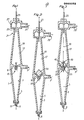
- the cyclone separator has a housing generally indicated as 1 which defines first and second cyclone separators 3,19.
- the first cyclone separator 3 operates with a reverse vortex cyclone action.
- the chamber 5 of the first separator is generally conical and in the illustrated embodiment has a vertically orientated axis.
- a fluid inlet 7 opens, preferably tangentially, into one end of the chamber 5, at the widest end, and fluid entering is directed onto a circular path by a scroll 9 forming an end wall of the chamber 5.
- An outlet 11 is disposed at the opposite end of the chamber 5. This outlet is coaxial with the axis of the chamber 5.
- a conical elastic tip 13 is provided at the outlet 11 and has an apex hole or holes dimensioned according to the application.
- the inner surface of the conical chamber 5 may be smooth or have helical grooving or raised protuberances to assist separation.
- the tip assembly may be provided with cleaning means for automatic cleaning, for example with high pressure fluid.
- a further outlet or transit passage 15 is provided at the end of the chamber 5 adjacent the inlet 7.
- the opening is coaxially disposed and leads into an end of a chamber 17 of the second cyclone separator 19.
- the second separator has a uni-direction flow action.
- the chamber is conical and converges from the inlet end to an outlet end 21 at which a plurality of outlet passages are disposed.
- Two outlets are shown in the illustrated embodiment.
- One outlet 23 is disposed on the axis, whilst a second outlet 25 is disposed radially and opens into an annular chamber 27 which communicates with the chamber 17 by way of an annular opening 29 surrounding a tubular passageway of the opening 23 which projects into the chamber 17.
- the walls of the chamber 17 may be smooth, or helically grooved or provided with raised protuberances to aid separation.
- the contaminated fluid enters the inlet 7, usually under the influence of a pump, and is directed onto the end wall of the chamber formed by the scroll 9. This creates a circular helical path within the chamber 5 and the fluid initially moves downwardly toward the apex outlet 11.
- Heavy contamination migrates to the walls of the chamber 5 and is ejected through the conical elastic tip 13. Material from which heavy contamination has been removed passes upwardly, i.e., in the reverse flow direction, with axial and spin velocity to the outlet 15 and into the chamber 17 of the Uniflow separator 19, where the light contamination is removed.
- the light contamination migrates toward the central axis of the chamber 17 and passes out of the axially disposed outlet 23.
- the cleaned fluid passes out of the outlet 25 by way of the annular orifice 29 and chamber 27.
- heavy contamination is separated in the first cyclone separator and light contamination in the second cyclone separator.
- the principle on which the Uniflow cyclone separator operates is described in more detail in our co-pending European Patent Application No. 82300436.1.
- FIG 2 there is shown an alternative embodiment.
- the same reference numerals used in the description of figure 1 have been used to denote the same parts.
- the difference resides in the arrangement of the transitional passage 15.
- the passage has a plurality of passageways 35 which radiate from a centrally disposed opening 37 in the chamber 5 of the first separator 3. These passageways 35 emerge into the chamber 17 of the second separator 19.
- a plurality of circumferentially spaced openings are thus formed.
- “Disposed coaxially within these plurality of openings is a core stabilizer 39 which is conical in shape.
- the passageways 35 are preferably arranged to emerge tangentially, so that the fluid passing therethrough is directed on a helical path. More preferably, the passageways follow a spiral path to ensure that the fluid entering the second separator has the necessary spin velocity to give the desired separation.
- one spiral passageway 35 is provided which leads from the first separating chamber to the second separating chamber.
- one or more passageways may be provided according to different embodiments of the invention.
- the separator has first and second separating chambers 3,19 with a common wall therebetween.
- the wall comprises a conical core stabilizer 39 and has both circumferentially spaced openings 35 and an axial passage 40.
- the axial passage 40 communicates directly between the first and second separating chambers and allows contamination which has migrated to the axis of the first separating chamber 3 to pass directly into the second separating chamber 19, and thence to the rejects outlet 23 of the second chamber.
- the embodiment of figure 3 corresponds in operation to the embodiment of figure 2.
- the cone angle of the respective cyclone separators may be different from one another and they need not necessarily be located on a common axis. It is not essential that the Uniflow separator be conical; it may be cylindrical with a diameter corresponding to that of the transition passage 15, in fact the chamber of the reverse vortex flow separator may also be cylindrical.
- the housing of the two separators may be connected together in the region of the common separating wall accommodating the transition passage 15.
Landscapes
- Chemical & Material Sciences (AREA)
- Chemical Kinetics & Catalysis (AREA)
- Engineering & Computer Science (AREA)
- Mechanical Engineering (AREA)
- Cyclones (AREA)
- Organic Low-Molecular-Weight Compounds And Preparation Thereof (AREA)
Applications Claiming Priority (2)
| Application Number | Priority Date | Filing Date | Title |
|---|---|---|---|
| GB8215401 | 1982-05-26 | ||
| GB8215401 | 1982-05-26 |
Publications (2)
| Publication Number | Publication Date |
|---|---|
| EP0095382A2 true EP0095382A2 (fr) | 1983-11-30 |
| EP0095382A3 EP0095382A3 (fr) | 1984-09-05 |
Family
ID=10530646
Family Applications (1)
| Application Number | Title | Priority Date | Filing Date |
|---|---|---|---|
| EP83303005A Withdrawn EP0095382A3 (fr) | 1982-05-26 | 1983-05-25 | Séparateurs cyclones |
Country Status (10)
| Country | Link |
|---|---|
| US (1) | US4473478A (fr) |
| EP (1) | EP0095382A3 (fr) |
| JP (2) | JPS58214368A (fr) |
| KR (1) | KR840004874A (fr) |
| CA (1) | CA1197478A (fr) |
| DK (1) | DK236083A (fr) |
| ES (1) | ES8503972A1 (fr) |
| FI (1) | FI831823A7 (fr) |
| NO (1) | NO831829L (fr) |
| ZA (1) | ZA833625B (fr) |
Cited By (2)
| Publication number | Priority date | Publication date | Assignee | Title |
|---|---|---|---|---|
| US4693822A (en) * | 1984-02-23 | 1987-09-15 | United Kingdom Atomic Energy Authority | Fluidic contactors |
| WO1991006374A1 (fr) * | 1988-04-25 | 1991-05-16 | Milan Kolman | Ameliorations relatives a un hydrocylone |
Families Citing this family (17)
| Publication number | Priority date | Publication date | Assignee | Title |
|---|---|---|---|---|
| US4564443A (en) * | 1983-07-14 | 1986-01-14 | The Black Clawson Company | Reverse centrifugal cleaning of paper making stock |
| GB2230482A (en) * | 1986-10-03 | 1990-10-24 | Carroll Noel | Cyclone separator |
| US4927536A (en) * | 1989-03-21 | 1990-05-22 | Amoco Corporation | Hydrocyclone separation system |
| US5728262A (en) * | 1996-06-21 | 1998-03-17 | Tetra Laval Holdings & Finance, S.A. | Method and apparatus for removing neutral buoyancy contaminants from acellulosic pulp |
| US5769243A (en) * | 1996-07-30 | 1998-06-23 | Thermo Black Clawson Inc. | Through-flow cleaner with improved inlet section |
| US6109451A (en) * | 1998-11-13 | 2000-08-29 | Grimes; David B. | Through-flow hydrocyclone and three-way cleaner |
| US20070151922A1 (en) * | 2006-01-05 | 2007-07-05 | Mian Farouk A | Spiral Speed Separator (SSS) |
| US7669457B2 (en) * | 2007-07-24 | 2010-03-02 | Honeywell International Inc. | Apparatus and method of smoke detection |
| US8632624B2 (en) | 2011-10-13 | 2014-01-21 | General Electric Company | Fluid trap and method of separating fluids |
| WO2014117031A1 (fr) | 2013-01-24 | 2014-07-31 | Lp Amina Llc | Dispositif de classification |
| MX2018013717A (es) | 2016-05-12 | 2019-06-20 | Golden Renewable Energy Llc | Sistema ciclonico de enfriamiento y condensacion. |
| US10436525B2 (en) * | 2016-05-12 | 2019-10-08 | Golden Renewable Energy, LLC | Cyclonic cooling system |
| KR102399967B1 (ko) | 2016-06-21 | 2022-05-20 | 브레이븐 인바이론멘탈 엘엘씨 | 챠르 분리기 및 방법 |
| US10961062B2 (en) | 2016-06-21 | 2021-03-30 | Golden Renewable Energy, LLC | Bag press feeder assembly |
| US20170361268A1 (en) | 2016-06-21 | 2017-12-21 | Golden Renewable Energy | Char separator |
| SG11201811050PA (en) * | 2016-07-05 | 2019-01-30 | Golden Renewable Energy Llc | System and process for converting waste plastic into fuel |
| US10233393B2 (en) | 2016-07-08 | 2019-03-19 | Golden Renewable Energy, LLC | Heated airlock feeder unit |
Family Cites Families (11)
| Publication number | Priority date | Publication date | Assignee | Title |
|---|---|---|---|---|
| BE334250A (fr) * | ||||
| DE1069116B (de) * | 1952-09-24 | 1959-11-19 | Nichols Engineering S. Research Corporation, New- York, N. Y. (V.St.A.) | Verfahren und Vorrichtung zum Abscheiden von feste Stoffe enthaltenden Faserstoffaufschwemmungen an einem Hydrozyklon |
| FR1102737A (fr) * | 1954-06-18 | 1955-10-25 | Ateliers Et Chantiers Maritime | Dispositif dépoussiéreur |
| US3052361A (en) * | 1960-12-06 | 1962-09-04 | Marvin E Whatley | Liquid cyclone contactor |
| FR1314386A (fr) * | 1961-06-12 | 1963-01-11 | Forsch Ges Verfahrens Technik | Procédé de séparation mécanique de matières liquides ou solides d'une phase légère dispersée dans un milieu de phase plus lourde |
| FR1374128A (fr) * | 1963-11-12 | 1964-10-02 | Procédé et dispositif de triage de matières fibreuses en suspension dans des séparateurs à tourbillonnement | |
| US3306444A (en) * | 1965-06-17 | 1967-02-28 | Bird Machine Co | Hydrocyclone apparatus |
| CA964616A (en) * | 1973-07-20 | 1975-03-18 | Elast-O-Cor Products And Engineering Limited | Compound hydrocyclone having grooved under flow wall (s) |
| FI56868C (fi) * | 1976-11-01 | 1980-04-10 | Enso Gutzeit Oy | Hydrocyklonanordning |
| US4212653A (en) * | 1978-06-27 | 1980-07-15 | General Electric Company | Process and apparatus for separating particulate matter from gaseous media |
| US4265740A (en) * | 1979-12-17 | 1981-05-05 | Ingersoll-Rand Company | Centrifugal separator |
-
1983
- 1983-05-18 CA CA000428394A patent/CA1197478A/fr not_active Expired
- 1983-05-19 ZA ZA833625A patent/ZA833625B/xx unknown
- 1983-05-19 US US06/496,355 patent/US4473478A/en not_active Expired - Lifetime
- 1983-05-23 FI FI831823A patent/FI831823A7/fi not_active Application Discontinuation
- 1983-05-24 NO NO831829A patent/NO831829L/no unknown
- 1983-05-25 EP EP83303005A patent/EP0095382A3/fr not_active Withdrawn
- 1983-05-25 ES ES522694A patent/ES8503972A1/es not_active Expired
- 1983-05-25 DK DK236083A patent/DK236083A/da not_active Application Discontinuation
- 1983-05-25 KR KR1019830002295A patent/KR840004874A/ko not_active Withdrawn
- 1983-05-26 JP JP58091623A patent/JPS58214368A/ja active Pending
-
1985
- 1985-04-08 JP JP1985051159U patent/JPS60183049U/ja active Granted
Cited By (2)
| Publication number | Priority date | Publication date | Assignee | Title |
|---|---|---|---|---|
| US4693822A (en) * | 1984-02-23 | 1987-09-15 | United Kingdom Atomic Energy Authority | Fluidic contactors |
| WO1991006374A1 (fr) * | 1988-04-25 | 1991-05-16 | Milan Kolman | Ameliorations relatives a un hydrocylone |
Also Published As
| Publication number | Publication date |
|---|---|
| DK236083A (da) | 1983-11-27 |
| EP0095382A3 (fr) | 1984-09-05 |
| ES522694A0 (es) | 1985-04-16 |
| DK236083D0 (da) | 1983-05-25 |
| KR840004874A (ko) | 1984-10-31 |
| US4473478A (en) | 1984-09-25 |
| CA1197478A (fr) | 1985-12-03 |
| FI831823A0 (fi) | 1983-05-23 |
| ZA833625B (en) | 1984-02-29 |
| FI831823L (fi) | 1983-11-27 |
| NO831829L (no) | 1983-11-28 |
| ES8503972A1 (es) | 1985-04-16 |
| FI831823A7 (fi) | 1983-11-27 |
| JPS58214368A (ja) | 1983-12-13 |
| JPS60183049U (ja) | 1985-12-04 |
| JPS6318447Y2 (fr) | 1988-05-24 |
Similar Documents
| Publication | Publication Date | Title |
|---|---|---|
| US4473478A (en) | Cyclone separators | |
| US4578199A (en) | Cyclone separators | |
| US4378289A (en) | Method and apparatus for centrifugal separation | |
| EP2106297B2 (fr) | Dispositif et procédé de séparation d'un mélange de milieu fluide au moyen d'un cyclone | |
| US9687759B2 (en) | Apparatus for cyclone separation of a fluid flow into a gas phase and a liquid phase and vessel provided with such an apparatus | |
| US4722796A (en) | Cyclone separator | |
| US4711720A (en) | Tangentially staged hydrocyclones | |
| US4696737A (en) | Fiber recovery elutriating hydrocyclone | |
| US4309283A (en) | Hydrocyclone | |
| CN1265602A (zh) | 分离低浓度液体和高浓度液体混合物的装置与方法 | |
| US5965021A (en) | Hydrocyclone | |
| EP0037278A2 (fr) | Section d'évacuation pour hydrocyclones avec sorties concentriques pour la fraction traitée | |
| US5133861A (en) | Hydricyclone separator with turbulence shield | |
| US3543932A (en) | Vortex chamber reject control | |
| US5690812A (en) | Process and apparatus for the separation of solid matter via flotation | |
| SE507905C2 (sv) | Anordning för silning av massasuspensioner | |
| JP3773536B2 (ja) | 滞在時間の長い逆ハイドロサイクロンクリーナ | |
| CN117642538A (zh) | 从悬浮液中离心分离固体的水力旋流器装置 | |
| US4375411A (en) | Device for limiting vortex flow | |
| AU598505B2 (en) | Cyclone separator | |
| AU1612097A (en) | Hydrocyclone separator | |
| US20220126305A1 (en) | Multiple Inlets Cyclo-Hydrocyclone Separator | |
| SU969319A1 (ru) | Устройство дл разделени суспензий | |
| AU2024385370A1 (en) | Hydrocyclone | |
| CS220963B1 (sk) | Vírový odlučovač na vtoku do čerpadla |
Legal Events
| Date | Code | Title | Description |
|---|---|---|---|
| PUAI | Public reference made under article 153(3) epc to a published international application that has entered the european phase |
Free format text: ORIGINAL CODE: 0009012 |
|
| AK | Designated contracting states |
Designated state(s): DE FR GB IT NL SE |
|
| PUAL | Search report despatched |
Free format text: ORIGINAL CODE: 0009013 |
|
| AK | Designated contracting states |
Designated state(s): DE FR GB IT NL SE |
|
| 17P | Request for examination filed |
Effective date: 19850205 |
|
| 17Q | First examination report despatched |
Effective date: 19860619 |
|
| STAA | Information on the status of an ep patent application or granted ep patent |
Free format text: STATUS: THE APPLICATION HAS BEEN WITHDRAWN |
|
| 18W | Application withdrawn |
Withdrawal date: 19861120 |
|
| RIN1 | Information on inventor provided before grant (corrected) |
Inventor name: CHIVRALL, GRAHAM BLAKELEY |