EP0095563A2 - Déflecteur de lumière commandé par l'interaction de deux faisceaux lumineux - Google Patents
Déflecteur de lumière commandé par l'interaction de deux faisceaux lumineux Download PDFInfo
- Publication number
- EP0095563A2 EP0095563A2 EP83102358A EP83102358A EP0095563A2 EP 0095563 A2 EP0095563 A2 EP 0095563A2 EP 83102358 A EP83102358 A EP 83102358A EP 83102358 A EP83102358 A EP 83102358A EP 0095563 A2 EP0095563 A2 EP 0095563A2
- Authority
- EP
- European Patent Office
- Prior art keywords
- deflector
- medium
- wavefront
- wavelength
- wavefronts
- Prior art date
- Legal status (The legal status is an assumption and is not a legal conclusion. Google has not performed a legal analysis and makes no representation as to the accuracy of the status listed.)
- Granted
Links
Images
Classifications
-
- G—PHYSICS
- G02—OPTICS
- G02F—OPTICAL DEVICES OR ARRANGEMENTS FOR THE CONTROL OF LIGHT BY MODIFICATION OF THE OPTICAL PROPERTIES OF THE MEDIA OF THE ELEMENTS INVOLVED THEREIN; NON-LINEAR OPTICS; FREQUENCY-CHANGING OF LIGHT; OPTICAL LOGIC ELEMENTS; OPTICAL ANALOGUE/DIGITAL CONVERTERS
- G02F1/00—Devices or arrangements for the control of the intensity, colour, phase, polarisation or direction of light arriving from an independent light source, e.g. switching, gating or modulating; Non-linear optics
- G02F1/29—Devices or arrangements for the control of the intensity, colour, phase, polarisation or direction of light arriving from an independent light source, e.g. switching, gating or modulating; Non-linear optics for the control of the position or the direction of light beams, i.e. deflection
- G02F1/293—Devices or arrangements for the control of the intensity, colour, phase, polarisation or direction of light arriving from an independent light source, e.g. switching, gating or modulating; Non-linear optics for the control of the position or the direction of light beams, i.e. deflection by another light beam, i.e. opto-optical deflection
-
- G—PHYSICS
- G02—OPTICS
- G02B—OPTICAL ELEMENTS, SYSTEMS OR APPARATUS
- G02B6/00—Light guides; Structural details of arrangements comprising light guides and other optical elements, e.g. couplings
- G02B6/02—Optical fibres with cladding with or without a coating
- G02B6/02033—Core or cladding made from organic material, e.g. polymeric material
-
- G—PHYSICS
- G02—OPTICS
- G02B—OPTICAL ELEMENTS, SYSTEMS OR APPARATUS
- G02B6/00—Light guides; Structural details of arrangements comprising light guides and other optical elements, e.g. couplings
- G02B6/02—Optical fibres with cladding with or without a coating
- G02B6/02057—Optical fibres with cladding with or without a coating comprising gratings
- G02B6/02076—Refractive index modulation gratings, e.g. Bragg gratings
- G02B6/02123—Refractive index modulation gratings, e.g. Bragg gratings characterised by the method of manufacture of the grating
- G02B6/02133—Refractive index modulation gratings, e.g. Bragg gratings characterised by the method of manufacture of the grating using beam interference
Definitions
- This invention relates to an optic device for light deflection and more particularly to an opto-optical light deflector/modulator.
- Electro optic devices are relatively fast since they are inertialess. They rotate the plane of polarization of incoming light by the linear electro optic Pockels effect in materials like potassium dihydrogen phosphate and by the addition of a following birefringent crystal cause the light to propagate as either the ordinary or extraordinary ray.
- electro optic and birefringent stages By cascading electro optic and birefringent stages, a multi-spot light deflector is realized.
- This device usually requires large voltages for the longitudinal effect, on the order of thousands of volts, and complicates the electronics when high deflection rates ( ⁇ ⁇ sec) are required. For the transverse effect smaller voltages are used, but a longer interaction length is required with the resulting reduction in aperture causing a reduction in resolution and alignment problem.
- the acousto-optic device operates by diffraction from a periodic structure, refractive index variation, introduced into an optically transparent material by a travelling acoustic wave.
- These are inherently small aperture devices because the small propagation velocity of the acoustic wave inside the material requires the cross section of the light beam to be small for the device to have a fast response time.
- An opto-optical light deflector is disclosed in U.S. patent 3,790,252.
- the deflection of the light beam is achieved by changing in a spatially non-homogeneous manner the refracted index of an interaction medium through which a control light beam and a controlling beam pass at an angle to each other.
- This approach varies the density of the diffraction material so that the density increases progressively, preferably linearly from one side to the other.
- One of his embodiments uses a diffraction pattern;however, this approach does not involve changing this diffraction pattern to achieve multiple deflection positions.
- An opto-optical light deflector/modulator in accordance with the present invention has a transparent optical active medium, for example, barium titanate.
- the deflector has means for providing first and second coherent wave fronts of wavelength (X 0 ) to travel in the medium to produce by interference an optically.generated standing wave that induces a periodic refractive index variation in the medium suitable for diffraction purposes.
- the device also includes means for providing a third wave front (X 1 ) to travel in said medium which is diffracted by the periodic refractive index variation induced by the first and second wave fronts.
- the wavelength of the first and second wave fronts are varied to alter the periodicity of the refractive index variation thereby causing the diffraction direction of the third wave front to be altered.
- This deflector uses optically generated standing waves to induce a periodic refractive index variation which is used for diffraction purposes.
- the device can be used as a deflector or as a modulator.
- an optically generated standing wave is formed in a transparent optical active medium to induce a periodic refractive index variation for diffraction purposes.
- the optical wave will propagate through the medium at the speed of light and impose no aperture/response time restrictions.
- the standing wave frequency can be shifted giving rise to the change in the diffraction angle.
- Deflection and/or modulation speed is restricted to the speed at which the wavelength can be shifted, or turned on and off in the case of modulation, and the life of the effect causing the refractive index modulation.
- Any number of light-induced effects including: population inversion, photo-bleaching, nonlinear effects giving rise to refractive index changes, molecular ordering and so forth can be employed.
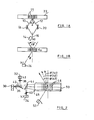
- the interference of two wavefronts 10 and 12 of wavelength ⁇ o that are obtained from light source 14'by use of a beam splitter 16 are directed by mirrors 18 and 20 to be incident at equal angles 8 to the transparent medium 22 normal and produce a periodic structure 23 of spacing
- Examples of light source 14 include lasers, such as Argon, GaAs, and dye lasers.
- Examples of the transparent medium are sodium vapor, barium titanate, bismuth silicon oxide, lithium niobate, ruby, liquid crystals and a liquid solution of organic saturable absorbers.
- the appropriate illumination angle is therefore given by:
- the beam at ⁇ 1 is deflected by an angle 20 by the structure created by 1 0 .
- the change in angle ⁇ obtained by differentiating the above equation and is given by:
- a 100 angstroms change in wavelength causes a 1° deflection.
- Such a wavelength change may be created by electro-optically or piezoelectrically tuning a dye laser, by electro-optic intracavity tuning of an Argon or Krypton laser or by current and/or thermal tuning of a solid state laser.
- a second embodiment is shown in Figure 2.
- a set of lasers 30, 32 and 34 each at a discrete wavelength ⁇ 1, ⁇ 2 and ⁇ 3 respectively, eliminates the need to vary the wavelength of the single laser used in the previous embodiment.
- the three beams 36, 38 and 40 from lasers 30, 32 and 34 are combined by beam splitters 42 and 44 and passed through a collimating surface 46 to produce a standing wave periodic structure 48 with the use of a mirror 50.
- the beam to be deflected is incident on the periodic structure from source 52.
- This arrangement produces a random digital effect since the transistion from one diffracting structure to the next is discontinuous and produces large angular effects operating at laser switching speeds. Additional deflection directions can be achieved by appropriately combining several lasers into the active medium.
- an effective large aperture modulator results. This occurs by altering the intensity of the structure-forming wavefronts and hence the strength of the periodic variations in refractive index will also vary, not necessarily in a linear manner. The subsequent strength of the diffracted wavefront will likewise vary. In either direction, diffracted or undiffracted, a signal modulation will be impressed on the controlled wavefront.
- it is a multi- direction light deflector and can additionally be used for multi-channel modulation and/or multiplexing of signals.
Landscapes
- Physics & Mathematics (AREA)
- General Physics & Mathematics (AREA)
- Optics & Photonics (AREA)
- Nonlinear Science (AREA)
- Engineering & Computer Science (AREA)
- Manufacturing & Machinery (AREA)
- Optical Modulation, Optical Deflection, Nonlinear Optics, Optical Demodulation, Optical Logic Elements (AREA)
- Electrochromic Elements, Electrophoresis, Or Variable Reflection Or Absorption Elements (AREA)
Applications Claiming Priority (2)
| Application Number | Priority Date | Filing Date | Title |
|---|---|---|---|
| US06/383,044 US4540244A (en) | 1982-05-28 | 1982-05-28 | Opto-optical light deflector/modulator |
| US383044 | 1982-05-28 |
Publications (3)
| Publication Number | Publication Date |
|---|---|
| EP0095563A2 true EP0095563A2 (fr) | 1983-12-07 |
| EP0095563A3 EP0095563A3 (en) | 1986-12-03 |
| EP0095563B1 EP0095563B1 (fr) | 1989-10-18 |
Family
ID=23511469
Family Applications (1)
| Application Number | Title | Priority Date | Filing Date |
|---|---|---|---|
| EP83102358A Expired EP0095563B1 (fr) | 1982-05-28 | 1983-03-10 | Déflecteur de lumière commandé par l'interaction de deux faisceaux lumineux |
Country Status (5)
| Country | Link |
|---|---|
| US (1) | US4540244A (fr) |
| EP (1) | EP0095563B1 (fr) |
| JP (1) | JPS58211744A (fr) |
| CA (1) | CA1191591A (fr) |
| DE (1) | DE3380746D1 (fr) |
Cited By (4)
| Publication number | Priority date | Publication date | Assignee | Title |
|---|---|---|---|---|
| GB2189038A (en) * | 1986-04-10 | 1987-10-14 | Stc Plc | Optical switching |
| EP0254509A1 (fr) * | 1986-07-22 | 1988-01-27 | BRITISH TELECOMMUNICATIONS public limited company | Dispositifs optiques sensibles à la longueur d'onde |
| EP0218555A3 (fr) * | 1985-10-11 | 1989-05-17 | Gesellschaft zur Förderung der industrieorientierten Forschung an den Schweizerischen Hochschulen und weiteren Institutionen | Procédé et dispositif pour la déflexion variable de la lumière et/ou pour la modulation spatiale de la lumière par diffraction |
| EP1301821A1 (fr) * | 2000-07-07 | 2003-04-16 | Biological Research Center Of The Hungarian Academy Of Sciences | Dispositif optique integre, commande par la lumiere |
Families Citing this family (11)
| Publication number | Priority date | Publication date | Assignee | Title |
|---|---|---|---|---|
| US5561541A (en) * | 1984-09-05 | 1996-10-01 | The United States Of America As Represented By The Secretary Of The Army | Frustrated total internal reflection optical power limiter |
| GB2189901B (en) * | 1986-04-25 | 1989-12-06 | Stc Plc | Laser induced optical fibre grating devices. |
| US4869579A (en) * | 1986-07-31 | 1989-09-26 | Technion Research & Development Foundation | Optical apparatus and method for beam coupling useful in light beam steering and spatial light modulation |
| US4958921A (en) * | 1986-09-19 | 1990-09-25 | The United States Of America As Represented By The United States Department Of Energy | Light-driven phase shifter |
| US4880296A (en) * | 1987-06-04 | 1989-11-14 | The United States Of America As Represented By The Secretary Of The Navy | Opto-optical bean deflector, modulator, and shaper |
| US5113282A (en) * | 1987-07-10 | 1992-05-12 | Hughes Aircraft Company | Dual light valve system with selective decoupling of light valves |
| FR2619938B1 (fr) * | 1987-09-01 | 1989-12-01 | Thomson Csf | Translateur de frequence pour onde du domaine infrarouge moyen |
| US5090795A (en) * | 1987-10-22 | 1992-02-25 | Hughes Aircraft Company | Integrated adaptive optics apparatus |
| JPH01121824A (ja) * | 1987-11-05 | 1989-05-15 | Hamamatsu Photonics Kk | 光学素子 |
| JPH01121825A (ja) * | 1987-11-05 | 1989-05-15 | Hamamatsu Photonics Kk | 光学素子 |
| JP5820101B2 (ja) * | 2010-05-17 | 2015-11-24 | 富士電機株式会社 | 光源装置 |
Family Cites Families (3)
| Publication number | Priority date | Publication date | Assignee | Title |
|---|---|---|---|---|
| US3790252A (en) * | 1972-02-23 | 1974-02-05 | Univ Case Western Reserve | Light controlled light beam deflector |
| GB1432947A (en) * | 1972-06-15 | 1976-04-22 | Emi Ltd | Light diverting and/or switching device |
| US4508431A (en) * | 1982-01-11 | 1985-04-02 | Massachusetts Institute Of Technology | Photorefractive laser beamsteering device |
-
1982
- 1982-05-28 US US06/383,044 patent/US4540244A/en not_active Expired - Lifetime
-
1983
- 1983-03-10 EP EP83102358A patent/EP0095563B1/fr not_active Expired
- 1983-03-10 DE DE8383102358T patent/DE3380746D1/de not_active Expired
- 1983-03-18 JP JP58044617A patent/JPS58211744A/ja active Granted
- 1983-03-25 CA CA000424514A patent/CA1191591A/fr not_active Expired
Cited By (7)
| Publication number | Priority date | Publication date | Assignee | Title |
|---|---|---|---|---|
| EP0218555A3 (fr) * | 1985-10-11 | 1989-05-17 | Gesellschaft zur Förderung der industrieorientierten Forschung an den Schweizerischen Hochschulen und weiteren Institutionen | Procédé et dispositif pour la déflexion variable de la lumière et/ou pour la modulation spatiale de la lumière par diffraction |
| GB2189038A (en) * | 1986-04-10 | 1987-10-14 | Stc Plc | Optical switching |
| GB2189038B (en) * | 1986-04-10 | 1989-11-29 | Stc Plc | Optical switching |
| EP0254509A1 (fr) * | 1986-07-22 | 1988-01-27 | BRITISH TELECOMMUNICATIONS public limited company | Dispositifs optiques sensibles à la longueur d'onde |
| WO1988000716A1 (fr) * | 1986-07-22 | 1988-01-28 | British Telecommunications Public Limited Company | Dispositifs optiques sensibles aux longueurs d'ondes |
| US4867522A (en) * | 1986-07-22 | 1989-09-19 | British Telecommunications Public Limited Company | Wavelength sensitive optical devices |
| EP1301821A1 (fr) * | 2000-07-07 | 2003-04-16 | Biological Research Center Of The Hungarian Academy Of Sciences | Dispositif optique integre, commande par la lumiere |
Also Published As
| Publication number | Publication date |
|---|---|
| EP0095563B1 (fr) | 1989-10-18 |
| DE3380746D1 (en) | 1989-11-23 |
| JPS58211744A (ja) | 1983-12-09 |
| JPS6157613B2 (fr) | 1986-12-08 |
| US4540244A (en) | 1985-09-10 |
| CA1191591A (fr) | 1985-08-06 |
| EP0095563A3 (en) | 1986-12-03 |
Similar Documents
| Publication | Publication Date | Title |
|---|---|---|
| EP0095563B1 (fr) | Déflecteur de lumière commandé par l'interaction de deux faisceaux lumineux | |
| US4006967A (en) | Directing optical beam | |
| KR0179037B1 (ko) | 광 스위치 | |
| US4243300A (en) | Large aperture phased element modulator/antenna | |
| US4945539A (en) | Acousto-optic tunable filter | |
| US5909304A (en) | Acousto-optic tunable filter based on isotropic acousto-optic diffraction using phased array transducers | |
| US3959739A (en) | Electro-optic tuning of organic dye laser | |
| US3731231A (en) | Acousto-optical modulator systems | |
| US9190800B2 (en) | Q-switched all-fiber laser | |
| EP0100418B1 (fr) | Déflecteur de lumière commandé par l'interaction de deux faisceaux lumineux | |
| US4105953A (en) | Chirped acousto-optic Q switch | |
| US6584260B2 (en) | Electro-optical device and a wavelength selection method utilizing the same | |
| JPH08222790A (ja) | レーザ装置 | |
| Mughal et al. | Compact acoustooptic high-speed variable attenuator for high-power applications | |
| US4921335A (en) | Optical phase conjugate beam modulator and method therefor | |
| US4880296A (en) | Opto-optical bean deflector, modulator, and shaper | |
| US3991383A (en) | Franz-Keldysh effect tuned laser | |
| US5173915A (en) | Semiconductor laser device | |
| US6204952B1 (en) | Bragg modulator | |
| JPH0585889B2 (fr) | ||
| US3529886A (en) | Iodic acid acousto-optic devices | |
| CA1240868A (fr) | Deflecteur de rayons acousto-optiques | |
| JPS6362916B2 (fr) | ||
| JPH0357455B2 (fr) | ||
| US3502391A (en) | Optical beam deflector using diverging or converging beams |
Legal Events
| Date | Code | Title | Description |
|---|---|---|---|
| PUAI | Public reference made under article 153(3) epc to a published international application that has entered the european phase |
Free format text: ORIGINAL CODE: 0009012 |
|
| AK | Designated contracting states |
Designated state(s): DE FR GB IT |
|
| 17P | Request for examination filed |
Effective date: 19840320 |
|
| PUAL | Search report despatched |
Free format text: ORIGINAL CODE: 0009013 |
|
| AK | Designated contracting states |
Kind code of ref document: A3 Designated state(s): DE FR GB IT |
|
| 17Q | First examination report despatched |
Effective date: 19880711 |
|
| GRAA | (expected) grant |
Free format text: ORIGINAL CODE: 0009210 |
|
| AK | Designated contracting states |
Kind code of ref document: B1 Designated state(s): DE FR GB IT |
|
| REF | Corresponds to: |
Ref document number: 3380746 Country of ref document: DE Date of ref document: 19891123 |
|
| ET | Fr: translation filed | ||
| ITF | It: translation for a ep patent filed | ||
| PLBE | No opposition filed within time limit |
Free format text: ORIGINAL CODE: 0009261 |
|
| STAA | Information on the status of an ep patent application or granted ep patent |
Free format text: STATUS: NO OPPOSITION FILED WITHIN TIME LIMIT |
|
| 26N | No opposition filed | ||
| PGFP | Annual fee paid to national office [announced via postgrant information from national office to epo] |
Ref country code: FR Payment date: 19910225 Year of fee payment: 9 |
|
| PGFP | Annual fee paid to national office [announced via postgrant information from national office to epo] |
Ref country code: DE Payment date: 19910323 Year of fee payment: 9 |
|
| ITTA | It: last paid annual fee | ||
| PGFP | Annual fee paid to national office [announced via postgrant information from national office to epo] |
Ref country code: GB Payment date: 19920210 Year of fee payment: 10 |
|
| PG25 | Lapsed in a contracting state [announced via postgrant information from national office to epo] |
Ref country code: FR Effective date: 19921130 |
|
| PG25 | Lapsed in a contracting state [announced via postgrant information from national office to epo] |
Ref country code: DE Effective date: 19921201 |
|
| REG | Reference to a national code |
Ref country code: FR Ref legal event code: ST |
|
| PG25 | Lapsed in a contracting state [announced via postgrant information from national office to epo] |
Ref country code: GB Effective date: 19930310 |
|
| GBPC | Gb: european patent ceased through non-payment of renewal fee |
Effective date: 19930310 |