EP0095577A2 - Procédé et dispositif de contrôle de l'harmonisation des axes d'un dispositif de visée optique et d'un dispositif orientable vers une cible, en particulier une arme - Google Patents
Procédé et dispositif de contrôle de l'harmonisation des axes d'un dispositif de visée optique et d'un dispositif orientable vers une cible, en particulier une arme Download PDFInfo
- Publication number
- EP0095577A2 EP0095577A2 EP83103566A EP83103566A EP0095577A2 EP 0095577 A2 EP0095577 A2 EP 0095577A2 EP 83103566 A EP83103566 A EP 83103566A EP 83103566 A EP83103566 A EP 83103566A EP 0095577 A2 EP0095577 A2 EP 0095577A2
- Authority
- EP
- European Patent Office
- Prior art keywords
- collimator
- measuring camera
- sighting
- target points
- sighting device
- Prior art date
- Legal status (The legal status is an assumption and is not a legal conclusion. Google has not performed a legal analysis and makes no representation as to the accuracy of the status listed.)
- Granted
Links
Images


Classifications
-
- F—MECHANICAL ENGINEERING; LIGHTING; HEATING; WEAPONS; BLASTING
- F41—WEAPONS
- F41G—WEAPON SIGHTS; AIMING
- F41G3/00—Aiming or laying means
- F41G3/32—Devices for testing or checking
- F41G3/323—Devices for testing or checking for checking the angle between the muzzle axis of the gun and a reference axis, e.g. the axis of the associated sighting device
Definitions
- the invention relates to a method and a device for checking synchronism deviations in the angle between the line of sight of an optical sighting device and a device which is spatially offset from the sighting device and can be directed to target points and which can be tracked by the sighting device, in particular a weapon, in which an optical test mark is generated and by the sighting device is projected to infinity.
- measuring cameras in front of the sighting device within the elevation range of the sighting line in at least two specific angular positions, with one;
- Crosshair projector in the focal plane of the measuring cameras, optical line marks are imaged on two rows of photodiodes which are perpendicular to one another, and whose positional deviation from a desired location makes a statement about the synchronism error.
- this known method has the disadvantage that measurement statements can only be obtained for two narrowly defined angular ranges and continuous measurement of the entire elevation range is not possible.
- This known method can also be carried out with collimators, with at least two angles being approached.
- a mirror is arranged on the device which can be aimed at target points and reflects a light beam emanating from an optical test mark arranged in the sighting device.
- the reflection image is brought into line with the test mark in the eyepiece.
- the sighting device and the device that can be aimed at target points are then passed through in the elevation area and the deviation of the reflection image in height and side is measured.
- a disadvantage of this known method is the difficulty in handling the voluminous mirror on the device that can be aimed at target points.
- the mirror is sensitive to damage and therefore unsuitable for use in the field.
- the measurement results are not automatically output in the known method.
- the object of the invention is to create a method and a device of the type mentioned in the introduction in which synchronism deviations can be measured continuously over the entire elevation range. This should not interfere with an existing one Sighting device should be necessary, the method should have a high accuracy and the device should be designed so that the method can be carried out even under difficult conditions, for example when used in unpaved terrain, hoists should not be used and a leveling of the target points judicial facility should not be necessary. Furthermore, an automatic output of the measurement results should be possible.
- the invention also offers the advantage that when the method is applied to a weapon, the attachment and lead angles required for a targeting operation can also be exactly determined and checked. The distance-dependent parallax correction can also be measured.
- a particular advantage of the device according to the invention is that it is easy to assemble and handle and that it can be used universally with suitably modified measuring camera mounts, with increased accuracy and greater robustness being achieved in comparison with known devices for checking the synchronism and the Measurement takes place automatically without the uncertainties of a manual setting and reading.
- the method and the device according to the invention are particularly suitable for checking synchronization deviations between the periscope and the weapon of a main battle tank, but other types of application are also possible.
- the method according to the invention and a corresponding device could also be used in connection with artillery units, in which several guns are controlled from one aiming device, or also with missile launching devices.
- a battle tank tower 1 is shown, on which a weapon 2 is arranged, which is shown in its basic position and a position pivoted upward by the angle ⁇ . Furthermore, a periscope 3 is arranged on the battle tank tower 1 spatially offset against the weapon 2, which has a eyepiece 33, a deflecting mirror 31 and a pivotable viewing mirror 32 in the view part 34 projecting above the battle tank tower 1 in a known manner and shown in more detail in FIG. 2.
- a mounting device 4 is placed on the battle tank tower 1 in the area of the view part 34 of the periscope 3, the mounting details 4 of which are described in more detail below and on which a collimator measuring camera 5 is pivotably arranged, which by means of an adjusting device 6 of the line of sight V of the periscope 3 nachge can be performed, the line of sight V including the horizontal angle '.
- a tracking device not shown and known per se, guides the weapon 2 such that its barrel core axis R runs parallel to the line of sight V and thus the angles ⁇ , ⁇ coincide except for synchronism deviations.
- An electrical inclination sensor 7 is arranged on the weapon 2 to determine its inclination, while an electrical inclination sensor 8 is arranged on the collimator measuring camera 5. Furthermore, on the base plate 40 of the holder 4, a dragonfly 46 and on the collimator measuring camera 5, a dragonfly 45 is arranged, each for precise alignment of the holder 4 on the roof of the main battle tank 1 and for adjusting the pivot axis 47 of the collimator measuring camera 5 the pivot axis 21 of the weapon 2 serve.
- a crosshair projector 9 shown in more detail in FIG. 3, is detachably fastened by means of a holder 10.
- the crosshair projector 9 has a lens 90, which can be adjusted by means of an adjusting device 91 in two directions perpendicular to the optical axis.
- a beam splitter 93 is arranged between the objective 90 and the eyepiece 92.
- a test mark designed as a crosshair is arranged between an illumination device 34 and the beam splitter 93, while an eyepiece grating plate 96 is arranged between the eyepiece 92 and the beam splitter 93.
- Another crosshair is arranged in the periscope 3 in a manner that is not specifically shown and known.
- the crosshair projector 9 is arranged such that its objective 90 lies approximately at a distance from the exit pupil of the eyepiece 33 on the periscope 3.
- the crosshair projector lens 90 acts as a collimator lens, i.e. the images of the crosshair 95 and the eyepiece reticle 96, which likewise represents a crosshair, are reproduced to infinity.
- the crosshair 95 and the crosshair 96 lie on the same optical axis.
- test crosshair 95 When the illumination 94 is switched on, the crosshair 95 is then projected onto the crosshair of the periscope 3 in the same way.
- the test crosshair 95 thus lies exactly on the sighting axis of the periscope 3 and the beam of rays emanating from it leaves the periscope 3 via the viewing mirror 32 in order to be received in the collimator measuring camera 5.
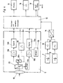
- the collimator measuring camera 5 shows the collimator measuring camera 5 attached to the holder 4 in more detail in a circuit diagram. It is a video camera known per se with a lens 50, which is followed by a beam splitter 51. The incident beam of rays is broken down into two sub-beams, one of which strikes a row of photodiodes 52h and the other strikes a row of photodiodes 52s. In this way, vertical and lateral displacements of the incident beam with respect to the optical axis of the objective 50 can be determined.
- the photodiode lines 52h and 52s are above video amplifiers 53h and 53s and digitization directions 54h and 54s connected to a control and evaluation unit 11, which contains a microprocessor and a memory.
- the collimator measuring camera 5 also contains a device 55 for clock generation and a device 56 for regulating the brightness.
- a display 15, on which the measured angular deviations are indicated in lines, and a printer 16 for printing a deviation curve are connected to the control and evaluation unit 11.
- the electrical inclination sensor 7 connected to the weapon 2 and the electrical inclination sensor 8 connected to the collimator measuring camera 5 are connected to the control and evaluation unit 11 via filters 12 and 13 and an analog-digital converter 14. The values output by the inclination sensors 7 and 8 are evaluated in the control and evaluation unit 11 and, if necessary, displayed or printed out.
- a device 17 can also be connected to the control and evaluation unit 11, which controls the actuating device 6 for tracking the collimator measuring camera 5.
- this device 17 does not necessarily have to be present, since in simpler embodiments, the collimator measuring camera 5 can also be adjusted manually.
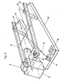
- the holder for the pivotable attachment of the collimator measuring camera 5 in front of the periscope 3 is shown in more detail in FIG. 5.
- It has a base plate 40, at one end of which tabs 42 are arranged, on which a bracket 41 is arranged pivotably about an axis 47. Between the tabs 42 there is a cutout 43 in the base plate 40, which is designed so that the base plate 40 can be placed on the roof of the main battle tank tower 1 such that the pivot axis 47 is at least approximately aligned with the axis of rotation of the viewing mirror 32 in the periscope 3.
- This correspondence of the two pivot axes need not be exact, but only has to satisfy the condition that light must still reach the lens 50 from the periscope 3 in all positions within the area to be traversed by the collimator measuring camera 5.
- the bracket 41 should be guided on the base plate 40 in a high-precision bearing.
- the base plate 40 can be designed differently for different types of vehicles. It can be arranged on the main battle tank tower 1 in a finely adjustable manner, its position being controllable by a dragonfly 46.
- the weapon can now be moved through the entire elevation range in any number of steps and the corresponding angular deviations between the weapon and the periscope are measured, evaluated and displayed or printed out.
Landscapes
- Engineering & Computer Science (AREA)
- General Engineering & Computer Science (AREA)
- Length Measuring Devices By Optical Means (AREA)
- Aiming, Guidance, Guns With A Light Source, Armor, Camouflage, And Targets (AREA)
- Telescopes (AREA)
Applications Claiming Priority (2)
| Application Number | Priority Date | Filing Date | Title |
|---|---|---|---|
| DE19823219916 DE3219916A1 (de) | 1982-05-27 | 1982-05-27 | Verfahren und einrichtung zur ueberpruefung von gleichlaufabweichungen zwischen einer optischen visiereinrichtung und einer auf zielpunkte richtbaren einrichtung, insbesondere einer waffe |
| DE3219916 | 1982-05-27 |
Publications (3)
| Publication Number | Publication Date |
|---|---|
| EP0095577A2 true EP0095577A2 (fr) | 1983-12-07 |
| EP0095577A3 EP0095577A3 (en) | 1985-09-11 |
| EP0095577B1 EP0095577B1 (fr) | 1989-02-08 |
Family
ID=6164612
Family Applications (1)
| Application Number | Title | Priority Date | Filing Date |
|---|---|---|---|
| EP83103566A Expired EP0095577B1 (fr) | 1982-05-27 | 1983-04-13 | Procédé et dispositif de contrôle de l'harmonisation des axes d'un dispositif de visée optique et d'un dispositif orientable vers une cible, en particulier une arme |
Country Status (3)
| Country | Link |
|---|---|
| EP (1) | EP0095577B1 (fr) |
| DE (2) | DE3219916A1 (fr) |
| ES (1) | ES522490A0 (fr) |
Cited By (5)
| Publication number | Priority date | Publication date | Assignee | Title |
|---|---|---|---|---|
| EP0179387A3 (en) * | 1984-10-25 | 1988-07-13 | Wegmann & Co. Gmbh | Device for carrying out dynamic comparative measurements in a fire control system for a directed weapon |
| EP0577017A1 (fr) * | 1992-06-27 | 1994-01-05 | DST Deutsche System-Technik GmbH | Dispositif pour tester le comportement dynamique de canons |
| EP1329683A1 (fr) * | 2002-01-16 | 2003-07-23 | Oerlikon Contraves Ag | Procédé et dispositif pour la compensation d'erreurs de tir et calculateur de système pour système d'arme |
| US7110101B2 (en) | 2002-06-14 | 2006-09-19 | Contraves Ag | Method and device for determining an angular error and use of the device |
| RU2341756C2 (ru) * | 2006-12-12 | 2008-12-20 | Открытое акционерное общество "Корпорация "Фазотрон-Научно-исследовательский институт радиостроения" | Способ проверки самолетного прицела |
Families Citing this family (3)
| Publication number | Priority date | Publication date | Assignee | Title |
|---|---|---|---|---|
| DE3623455C3 (de) * | 1986-07-11 | 1994-07-07 | Krauss Maffei Ag | Optisches Visier |
| DE3942922A1 (de) * | 1989-12-23 | 1991-06-27 | Rheinmetall Gmbh | Vorrichtung zur optischen messung von winkeln zwischen zwei annaehernd parallel verlaufenden optischen achsen |
| DE4344998C2 (de) * | 1993-12-30 | 1998-05-28 | Wegmann & Co Gmbh | Verfahren zur Messung des Seitenrichtungsfehlers eines in Elevation schwenkbaren, auf Zielobjekte ausrichtbaren Elements, insbesondere eines Waffenrohres, in Abhängigkeit vom Elevationswinkel, sowie Einrichtung zur Durchführung des Verfahrens |
Family Cites Families (3)
| Publication number | Priority date | Publication date | Assignee | Title |
|---|---|---|---|---|
| SE325494B (fr) * | 1969-04-22 | 1970-06-29 | Bofors Ab | |
| US4020739A (en) * | 1976-07-16 | 1977-05-03 | The United States Of America As Represented By The Secretary Of The Army | Fire control system |
| DE2951108C2 (de) * | 1979-12-19 | 1983-11-17 | Krauss-Maffei AG, 8000 München | Verfahren und Vorrichtung zur Überprüfung des Gleichlaufs der Visierlinie eines Periskops mit auf Zielpunkte richtbaren Elementen |
-
1982
- 1982-05-27 DE DE19823219916 patent/DE3219916A1/de not_active Withdrawn
-
1983
- 1983-04-13 DE DE8383103566T patent/DE3379174D1/de not_active Expired
- 1983-04-13 EP EP83103566A patent/EP0095577B1/fr not_active Expired
- 1983-05-17 ES ES522490A patent/ES522490A0/es active Granted
Cited By (6)
| Publication number | Priority date | Publication date | Assignee | Title |
|---|---|---|---|---|
| EP0179387A3 (en) * | 1984-10-25 | 1988-07-13 | Wegmann & Co. Gmbh | Device for carrying out dynamic comparative measurements in a fire control system for a directed weapon |
| EP0577017A1 (fr) * | 1992-06-27 | 1994-01-05 | DST Deutsche System-Technik GmbH | Dispositif pour tester le comportement dynamique de canons |
| EP1329683A1 (fr) * | 2002-01-16 | 2003-07-23 | Oerlikon Contraves Ag | Procédé et dispositif pour la compensation d'erreurs de tir et calculateur de système pour système d'arme |
| CN100480614C (zh) * | 2002-01-16 | 2009-04-22 | 厄利康肯特维斯股份公司 | 射击误差的补偿方法和装置以及武器系统的系统计算机 |
| US7110101B2 (en) | 2002-06-14 | 2006-09-19 | Contraves Ag | Method and device for determining an angular error and use of the device |
| RU2341756C2 (ru) * | 2006-12-12 | 2008-12-20 | Открытое акционерное общество "Корпорация "Фазотрон-Научно-исследовательский институт радиостроения" | Способ проверки самолетного прицела |
Also Published As
| Publication number | Publication date |
|---|---|
| EP0095577A3 (en) | 1985-09-11 |
| EP0095577B1 (fr) | 1989-02-08 |
| DE3379174D1 (en) | 1989-03-16 |
| DE3219916A1 (de) | 1983-12-01 |
| ES8402929A1 (es) | 1984-03-01 |
| ES522490A0 (es) | 1984-03-01 |
Similar Documents
| Publication | Publication Date | Title |
|---|---|---|
| DE2710904C2 (fr) | ||
| DE19833996C1 (de) | Elektronisches Nivellier und Verfahren zur Videoanzielung | |
| DE2426785C3 (de) | Vorrichtung zum Ausrichten der zwei optischen Achsen einer kombinierten Zielfernrohr/IR-Goniometer-Anlage | |
| DE3341232A1 (de) | Feuerleitsystem | |
| DE2951108C2 (de) | Verfahren und Vorrichtung zur Überprüfung des Gleichlaufs der Visierlinie eines Periskops mit auf Zielpunkte richtbaren Elementen | |
| CH656216A5 (de) | Verfahren und anordnung zur pruefung der uebereinstimmung von visier- und ziellinien. | |
| EP0095577B1 (fr) | Procédé et dispositif de contrôle de l'harmonisation des axes d'un dispositif de visée optique et d'un dispositif orientable vers une cible, en particulier une arme | |
| EP0179387B1 (fr) | Dispositif pour effectuer des mesures comparatives dynamiques dans un système de conduite de tir pour arme orientable | |
| EP0179186B1 (fr) | Dispositif d'harmonisation des lignes de collimation de deux appareils d'observation | |
| EP1875150B1 (fr) | Dispositif d'alignement et procede pour aligner un axe d'un simulateur de tir sur la ligne de mire d'une arme | |
| CH680951A5 (fr) | ||
| DE3623455C3 (de) | Optisches Visier | |
| DE3246805A1 (de) | Justiervorrichtung fuer die feuerleitanlage eines kampffahrzeugs | |
| EP0036099A1 (fr) | Une combinaison de miroir et prisme pour l'harmonisation des axes optiques | |
| DE3942922C2 (fr) | ||
| DE102011116844A1 (de) | Justierapparat und Justieranordnung für Zielmittel an Waffen, insbesondere an Handwaffen | |
| DE3739698A1 (de) | Optronisches visier | |
| DE3919851C1 (de) | Zieleinrichtung für Lenkflugkörper | |
| DE2054323A1 (de) | Vorrichtung zum anvisieren und zielverfolgen fuer ein lenksystem eines lenkflugkoerpers | |
| DD288877A5 (de) | Anordnung zur winkelmessung und richtungsfluchtung, insbesondere mit einem theodoliten | |
| DE1472279C (de) | Zielfernrohr | |
| DE4123449A1 (de) | Zielfernrohr eines geodaetischen instruments | |
| DE2054387C (de) | Als Tag Nacht Zielgerat ausge bildetes kombiniertes Sichtgerat | |
| DD249544A1 (de) | Anordnung zur erkennung der zielpunktlage bei zielfernrohren | |
| DE2409226C3 (de) | Nachtfernsehzielanlage, insbesondere für Panzer |
Legal Events
| Date | Code | Title | Description |
|---|---|---|---|
| PUAI | Public reference made under article 153(3) epc to a published international application that has entered the european phase |
Free format text: ORIGINAL CODE: 0009012 |
|
| AK | Designated contracting states |
Designated state(s): CH DE GB LI NL |
|
| PUAL | Search report despatched |
Free format text: ORIGINAL CODE: 0009013 |
|
| AK | Designated contracting states |
Designated state(s): CH DE GB LI NL |
|
| 17P | Request for examination filed |
Effective date: 19860224 |
|
| 17Q | First examination report despatched |
Effective date: 19870910 |
|
| GRAA | (expected) grant |
Free format text: ORIGINAL CODE: 0009210 |
|
| AK | Designated contracting states |
Kind code of ref document: B1 Designated state(s): CH DE GB LI NL |
|
| REF | Corresponds to: |
Ref document number: 3379174 Country of ref document: DE Date of ref document: 19890316 |
|
| GBT | Gb: translation of ep patent filed (gb section 77(6)(a)/1977) | ||
| PLBE | No opposition filed within time limit |
Free format text: ORIGINAL CODE: 0009261 |
|
| STAA | Information on the status of an ep patent application or granted ep patent |
Free format text: STATUS: NO OPPOSITION FILED WITHIN TIME LIMIT |
|
| 26N | No opposition filed | ||
| PGFP | Annual fee paid to national office [announced via postgrant information from national office to epo] |
Ref country code: GB Payment date: 19920422 Year of fee payment: 10 |
|
| PGFP | Annual fee paid to national office [announced via postgrant information from national office to epo] |
Ref country code: NL Payment date: 19920430 Year of fee payment: 10 |
|
| PGFP | Annual fee paid to national office [announced via postgrant information from national office to epo] |
Ref country code: CH Payment date: 19920513 Year of fee payment: 10 |
|
| PGFP | Annual fee paid to national office [announced via postgrant information from national office to epo] |
Ref country code: DE Payment date: 19920602 Year of fee payment: 10 |
|
| PG25 | Lapsed in a contracting state [announced via postgrant information from national office to epo] |
Ref country code: GB Effective date: 19930413 |
|
| PG25 | Lapsed in a contracting state [announced via postgrant information from national office to epo] |
Ref country code: LI Effective date: 19930430 Ref country code: CH Effective date: 19930430 |
|
| PG25 | Lapsed in a contracting state [announced via postgrant information from national office to epo] |
Ref country code: NL Effective date: 19931101 |
|
| GBPC | Gb: european patent ceased through non-payment of renewal fee |
Effective date: 19930413 |
|
| NLV4 | Nl: lapsed or anulled due to non-payment of the annual fee | ||
| REG | Reference to a national code |
Ref country code: CH Ref legal event code: PL |
|
| PG25 | Lapsed in a contracting state [announced via postgrant information from national office to epo] |
Ref country code: DE Effective date: 19940101 |