EP0095701A1 - Belichtungsstation - Google Patents
Belichtungsstation Download PDFInfo
- Publication number
- EP0095701A1 EP0095701A1 EP83105110A EP83105110A EP0095701A1 EP 0095701 A1 EP0095701 A1 EP 0095701A1 EP 83105110 A EP83105110 A EP 83105110A EP 83105110 A EP83105110 A EP 83105110A EP 0095701 A1 EP0095701 A1 EP 0095701A1
- Authority
- EP
- European Patent Office
- Prior art keywords
- sheet
- exposure
- container
- plate
- air
- Prior art date
- Legal status (The legal status is an assumption and is not a legal conclusion. Google has not performed a legal analysis and makes no representation as to the accuracy of the status listed.)
- Granted
Links
- 239000000463 material Substances 0.000 claims abstract description 5
- 238000004080 punching Methods 0.000 claims description 5
- 238000000034 method Methods 0.000 claims description 2
- 230000033001 locomotion Effects 0.000 description 4
- 238000012545 processing Methods 0.000 description 4
- 238000011161 development Methods 0.000 description 2
- 238000010894 electron beam technology Methods 0.000 description 2
- 238000012986 modification Methods 0.000 description 2
- 230000004048 modification Effects 0.000 description 2
- 239000002245 particle Substances 0.000 description 2
- 230000000750 progressive effect Effects 0.000 description 2
- 230000003068 static effect Effects 0.000 description 2
- 235000010678 Paulownia tomentosa Nutrition 0.000 description 1
- 240000002834 Paulownia tomentosa Species 0.000 description 1
- 230000003213 activating effect Effects 0.000 description 1
- 230000004888 barrier function Effects 0.000 description 1
- 238000012937 correction Methods 0.000 description 1
- 230000026058 directional locomotion Effects 0.000 description 1
- 230000000694 effects Effects 0.000 description 1
- 235000016709 nutrition Nutrition 0.000 description 1
- 239000002985 plastic film Substances 0.000 description 1
- 229920006255 plastic film Polymers 0.000 description 1
- 230000001105 regulatory effect Effects 0.000 description 1
- 230000000284 resting effect Effects 0.000 description 1
- 238000000926 separation method Methods 0.000 description 1
Images
Classifications
-
- G—PHYSICS
- G03—PHOTOGRAPHY; CINEMATOGRAPHY; ANALOGOUS TECHNIQUES USING WAVES OTHER THAN OPTICAL WAVES; ELECTROGRAPHY; HOLOGRAPHY
- G03G—ELECTROGRAPHY; ELECTROPHOTOGRAPHY; MAGNETOGRAPHY
- G03G15/00—Apparatus for electrographic processes using a charge pattern
- G03G15/65—Apparatus which relate to the handling of copy material
- G03G15/6502—Supplying of sheet copy material; Cassettes therefor
-
- B—PERFORMING OPERATIONS; TRANSPORTING
- B65—CONVEYING; PACKING; STORING; HANDLING THIN OR FILAMENTARY MATERIAL
- B65H—HANDLING THIN OR FILAMENTARY MATERIAL, e.g. SHEETS, WEBS, CABLES
- B65H3/00—Separating articles from piles
- B65H3/08—Separating articles from piles using pneumatic force
- B65H3/14—Air blasts producing partial vacuum
-
- B—PERFORMING OPERATIONS; TRANSPORTING
- B65—CONVEYING; PACKING; STORING; HANDLING THIN OR FILAMENTARY MATERIAL
- B65H—HANDLING THIN OR FILAMENTARY MATERIAL, e.g. SHEETS, WEBS, CABLES
- B65H9/00—Registering, e.g. orientating, articles; Devices therefor
- B65H9/20—Assisting by photoelectric, sonic, or pneumatic indicators
-
- G—PHYSICS
- G03—PHOTOGRAPHY; CINEMATOGRAPHY; ANALOGOUS TECHNIQUES USING WAVES OTHER THAN OPTICAL WAVES; ELECTROGRAPHY; HOLOGRAPHY
- G03B—APPARATUS OR ARRANGEMENTS FOR TAKING PHOTOGRAPHS OR FOR PROJECTING OR VIEWING THEM; APPARATUS OR ARRANGEMENTS EMPLOYING ANALOGOUS TECHNIQUES USING WAVES OTHER THAN OPTICAL WAVES; ACCESSORIES THEREFOR
- G03B27/00—Photographic printing apparatus
- G03B27/32—Projection printing apparatus, e.g. enlarger, copying camera
- G03B27/52—Details
- G03B27/58—Baseboards, masking frames, or other holders for the sensitive material
- G03B27/585—Handling cut photosensitive sheets
Definitions
- the invention relates to an exposure station for photosensitive materials, with an exposure table and with a sheet dispenser, which has a rectangular sheet container, the front, rear and side walls of which form the container border, with a height-adjustable base which can be raised and lowered within the container border.
- the materials to be exposed are stacked and are separated from the stack and sequentially transported as individual sheets to an exposure table.
- the invention relates in particular to the aerodynamic separation and the transport of the sheets individually to a further processing station, for example the exposure table in the exposure station.
- the individual sheet can then be precisely positioned in the processing station for subsequent operations.
- a sheet feed device which has a stationary blower above a rotating endless, perforated conveyor belt, which pressurizes the conveyor belt with vacuum, so that the top sheet of a stack, which is located on a platform, to the Bottom of the conveyor belt is sucked.
- the conveyor belt revolves within a suction space, which is enclosed by side walls.
- This sheet feed device tung has an automatically height-adjustable platform that is vertically adjustable below the conveyor belt.
- the negative pressure generated by the blower is strong enough to lift the top sheet from a stack of cardboard sheets and there are also transport devices which convey such a sheet horizontally with respect to the original platform position.
- the object of the invention is to provide an exposure station which comprises a sheet dispensing device and an exposure table, and in which the sheets to be exposed are individually detached from a stack and the feed and the further transport of the individual sheet to or from the exposure table are aerodynamically controlled, that a simultaneous double or multiple transport of sheets is avoided.
- a projection is attached to the front wall of the sheet container, which partially in the interior of the container se protrudes that a guide plate for an air flow is guided at a distance and parallel and above the top level of the container, that the guide plate has a blade stop on its rear part and at least one rearward and at least one forward air nozzle on the underside and that the projection and the front part of the guide plate form an exit path for the sheets stacked in the container.
- the exposure table which receives a sheet coming from the exit path, has a rectangular exposure plate with a number of passages, if an exposure beam scans the top level of the exposure table vertically, devices move the exposure table a predetermined distance perpendicular to the beam path and forth, a device creates a vacuum or air flow through the passages for sucking or lifting a sheet and an air nozzle-carrying plate is arranged above and parallel to the plane of the exposure table and has a number of air nozzles open to the underside of the plate which move a sheet in a perpendicular position on the exposure plate to a predetermined position and can convey the sheet through an exit passage.
- devices for punching holes in the sheet Sen Sensors for determining the position of the sheet, means for sequentially applying air pressure and / or vacuum through the air nozzles and the passages are present, and furthermore means for separating and separating the sheets of a stack in the container.
- the invention solves the problem in such a way that first the top sheet of a stack of sheets is moved in an opposite direction to the desired transport direction until a stop is reached and then the direction of movement is reversed in the desired transport direction.
- the individual, the exposure table supplied l leaf is exposed to light from an exposure source, for example as is the case in a copying machine, or exposed by means of a laser beam or other light beam or an electron beam or with any other particle.
- the exposure station is particularly suitable for the exposure of sheets which have a photosensitive layer on their surface.
- the sheet supplied by the sheet dispenser to the exposure table is positioned thereon with great precision until it reaches a desired position by means of iterative or progressive approximation values (trial and error) of air jet bursts.
- the exposure table is then moved under the exposure device. After exposure, air currents lift out Air jets the sheet from the exposure table and this exits the exposure station. Additional operations can be performed on the exposure table, such as punching holes in the sheet and the like.
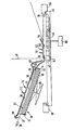
- the figure shows a partially sectioned, schematic side view of the exposure station according to the invention.
- the invention relates to an exposure station having a sheet dispensing device for bla a t:-shaped material as the sheet dispensing apparatus comprises a sheet container 10, for example paper, cards, computer cards, plastic films, photosensitive films, lithographic printing plates or the like, which in the. is essentially rectangular and its rear wall 12, front wall 14 and side walls, which are not shown in the drawing, form the container border.
- the front wall 14 has a projection or a lip 16 which partially projects and projects into the interior of the container.
- the container has a movable bottom 18 which is raised and lowered by a suitable device 20, such as a scissor hoist, so that all of the sheets 22 stacked on the bottom are moved up and down within the center of the container rim.
- a suitable device 20 such as a scissor hoist
- Detectors not shown, determine the actual position of the top sheet and the approximate number of sheets still present in the container.
- Means are also provided, such as air nozzles 26, for briefly reefing the sheet stack 23 from the general direction indicated by an arrow 27. In the preferred embodiment, these air nozzles 26, it can also be just a single air nozzle, are directed slightly downward into the sheet stack 23. This causes some air to enter between some of the upper leaves and to separate them somewhat, if not completely.
- a rectangular guide plate 28 with air nozzles which has a C-shaped blade holding stop 30 at its rear part.
- Attached to the baffle 28 is a rearward air nozzle 32 and a forward air nozzle 34.
- more than two air nozzles can also be attached to the plate, one half of which is directed towards the rear and the other half towards the front.
- the air nozzle 32 is activated, causing an air flow of high speed and low static pressure on the top side of the top sheet.
- a pressure difference is built up because air of lower speed but higher static pressure exists under the top sheet. This pressure difference causes the top sheet to be lifted like a wing.
- the rear air nozzle 32 is turned off and the forward air nozzle 34 is activated.
- the sheet lifting and transport action mentioned above takes place, but now in the forward direction, i.e. in the direction of an arrow 38.
- the sheet then passes through an exit path 40 which is formed by the projection 16 and the front part of the guide plate 28. Any movement to lower the top sheets by the air nozzle 34 is stopped by the protrusion 16.
- the exit path 40 opens out in the form of a dovetail in the direction of the exposure table 44 to which the photo-temp sensitive sheets are fed to be exposed thereon by an exposure device, which is not shown.
- the exposure table 44 includes an exposure plate 42 which is slidable along a predetermined path, such as a frame of the exposure table 44.
- the exposure plate 42 has a number of passages 62, which are connected to a device 60, for example a vacuum and compressed air generating pump, in order to hold a delivered sheet wrinkle-free on the surface of the exposure plate 42.
- the exposure plate 42 is reciprocated in the directions of the double arrow 46 by suitable means.
- a photosensitive sheet is exposed by an exposure beam 48 as soon as the exposure plate moves under the beam which is perpendicular to the plane of the exposure table 44.
- the exposure beam can be a laser beam, the beam of a controlled light source with one or more different wavelengths, an electron beam, an ionized particle beam or the like.
- a plate 50 carrying air nozzles 52 is located above the exposure plate 42.
- the air nozzles 52 are constructed similarly to the air nozzles 32 and 34. These air jets have a regulated air flow and are oriented so that they can be selectively activated to give a sheet a precise and sufficient lift and directional movement, and this to position on the surface of the exposure plate with great accuracy by means of an iterative control system that works with progressive nutritional values or another control system.
- Suitable position sensors 64 for example light barriers, interact with the sheet and the exposure plate 42.
- the air nozzles on the plate 50 are oriented vertically to perform the necessary sheet positioning.
- devices 56 and 58 such as punches for perforating the sheet, are arranged on the opposite ends of the exposure table.
- a sheet is conveyed through exit path 40 to exposure plate 42.
- a vacuum is applied to the passages 62 of the exposure plate to hold the sheet in place.
- the exposure plate then moves backward and the sheet thereon is scanned by the exposure beam 48.
- the vacuum in the passages 62 is released and switched to an air flow that flows through the passages 62 and slightly raises the sheet.
- One or more of the air nozzles 52 are turned on and give the blade a forward movement so that it exits a wing through an exit passage 54 due to the previously described buoyancy effect is conveyed through.
- holes can be punched into the sheet by means of the punching devices 56 and 58.
- additional air nozzles can convey the sheet to another processing station, such as a development station.
Landscapes
- Physics & Mathematics (AREA)
- General Physics & Mathematics (AREA)
- Engineering & Computer Science (AREA)
- Mechanical Engineering (AREA)
- Sheets, Magazines, And Separation Thereof (AREA)
- Magnetic Resonance Imaging Apparatus (AREA)
- Gas-Filled Discharge Tubes (AREA)
- Electronic Switches (AREA)
Abstract
Description
- Die Erfindung betrifft eine Belichtungsstation für fotoempfindliche Materialien, mit einem Belichtungstisch und mit einer Blattspendevorrichtung, die einen rechteckigen Blattbehälter aufweist, dessen Vorder-, Rück- und Seitenwände die Behälterumrandung bilden, mit einem höhenverstellbaren Boden, der innerhalb der Behälterumrandung anheb- und absenkbar ist.
- Im allgemeinen sind die zu belichtenden Materialien gestapelt und werden von dem Stapel abgetrennt und aufeinanderfolgend als einzelne Blätter zu einem Belichtungstisch transportiert. Die Erfindung betrifft insbesondere die aerodynamische Vereinzelung und den Transport der Blätter einzeln zu einer weiteren Bearbeitungsstation, beispielsweise den Belichtungstisch in der Belichtungsstation. Das einzelne Blatt kann dann in der Bearbeitungsstation für nachfolgende Operationen genau positioniert werden.
- Aus der US-PS 3 610 577 ist eine Blattzufuhrvorrichtung bekannt, die oberhalb eines umlaufenden endlosen, gelochten Transportbandes ein ortsfestes Gebläse aufweist, welches das Transportband mit Unterdruck beaufschlagt, so daß das oberste Blatt eines Stapels, der sich auf einer Plattform befindet, an die Unterseite des Transportbandes angesaugt wird. Das Transportband läuft innerhalb eines Ansaugraumes um, der von Seitenwänden eingeschlossen ist. Di.ese Blattzufuhrvorrichtung besitzt eine automatisch höhenverstellbare Plattform, die unterhalb des Transportbandes vertikal verstellbar ist. Der von dem Gebläse erzeugte Unterdruck ist stark genug, um das oberste Blatt von einem Stapel von kartonartigen Blättern zu heben und des weiteren sind Transporteinrichtungen vorhanden, welche ein derartiges Blatt in bezug auf die ursprüngliche Plattformposition horizontal weiterbefördern.
- Im Stand der Technik ist es auch bekannt, Blätter aerodynamisch voneinander zu trennen und mit Hilfe von Luftdüsen entlang einem vorgegebenen Führungswe- zu bewegen. Ein Luftkissen mit unterschiedlichen Drücken an jeder Seite des Blattes bewerkstelligt das erforderliche Anheben und liefert den Strömungswiderstand, um die Blätter in die gewünschte Richtung zu transportieren.
- Aufgabe der Erfindung ist es, eine Belichtungsstation zu schaffen, die eine Blattspendevorrichtung und einen Belichtungstisch umfaßt, und bei der die zu belichtenden Blätter einzeln von einem Stapel abgelöst und die Zufuhr und der Weitertransport des einzelnen Blattes zu oder von dem Belichtungstisch aerodynamisch so gesteuert werden, daß ein gleichzeitiger Doppel- oder Mehrfachtransport von Blättern vermieden wird.
- Diese Aufgabe wird erfindungsgemäß dadurch gelöst, daß an der Vorderwand des Blattbehälters ein Vorsprung angebracht ist, der in das Innere des Behälters teilweise hineinragt, daß eine Leitplatte für einen Luftstrom im Abstand sowie parallel und oberhalb zu der obersten Ebene des Behälters geführt ist, daß die Leitplatte einen Blatthalteanschlag an ihrem hinteren Teil und zumindest eine nach hinten und zumindest eine nach vorne gerichtete Luftdüse an der Unterseite aufweist und daß der Vorsprung und der Vorderteil der Leitplatte eine Austrittsbahn für die im Behälter gestapelten Blätter bilden.
- In Ausgestaltung der Erfindung weist der Belichtungstisch, der ein von der Austrittsbahn kommendes Blatt aufnimmt, eine rechteckförmige Belichtungsplatte mit einer Anzahl von Durchlässen auf, tastet ein Belichtungsstrahl die oberste Ebene des Belichtungstisches senkrecht ab, verschieben Einrichtungen den Belichtungstisch eine vorgegebene Strecke senkrecht zu dem Strahlenpfad hin und her, erzeugt eine Einrichtung ein Vakuum oder einen Luftstrom durch die Durchlässe hindurch zum Ansaugen oder Abheben eines Blattes und ist eine Luftdüsen tragende Platte oberhalb und parallel zu der Ebene des Belichtungstisches angeordnet und weist eine Anzahl der zu der Unterseite der Platte hin offenen Luftdüsen auf, die ein Blatt in zueinander senkrechten Richtungen auf der Belichtungsplatte in eine vorgegebene Position bewegen und das Blatt durch einen Austrittsdurchlaß befördern können.
- In vorteilhafter Weiterbildung der Erfindung sind Einrichtungen zum Stanzen von Löchern in dem Blatt, Sensoren zum Feststellen der Position des Blattes, Einrichtungen zum aufeinanderfolgenden Beaufschlagen mit Luftdruck und/oder Vakuum durch die Luftdüsen und die Durchlässe vorhanden, und des weiteren eine Einrichtung zum Vereinzeln und Trennen der Blätter eines Stapels in dem Behälter.
- Die Erfindung löst das gestellte Problem in der Weise, daß zuerst das oberste Blatt eines Blattstapels in eine entgegengesetzte Richtung zu der gewünschten Transportrichtung bis zum Erreichen eines Stopanschlags bewegt wird und anschließend die Bewegungsrichtung in die gewünschte Transportrichtung umgekehrt wird. Das einzelne, dem Belichtungstisch zugeführtl Blatt wird von einer Belichtungsquelle belichtet, beispielsweise wie dies in einer Kopiermaschine der Fall ist, oder mittels eines Laserstrahls oder eines sonstigen Lichtstrahls oder eines Elektronenstrahls belichtet oder mit einem sonstigen Teilchenstrahl. Die Belichtungsstation ist insbesondere für die Belichtung von Blättern geeignet, die auf ihrer Oberfläche eine fotoempfindliche Schicht tragen. Während eines typischen Verarbeitungsschrittes wird das von der Blattspendevorrichtung zu dem Belichtungstisch gelieferte Blatt auf diesem mittels iterierender oder fortschreitender Nährungswerte (trial and error) von Luftdüsenstößen mit großer Genauigkeit bis zum Erreichen einer gewünschten Stellung positioniert. Der Belichtungstisch wird anschließend unter die Belichtungseinrichtung bewegt. Nach der Belichtung heben Luftströme aus Luftdüsen das Blatt von dem Belichtungstisch ab und dieses tritt aus der Belichtungsstation aus. Es können noch zusätzliche Arbeitsgänge auf dem Belichtungstisch durchgeführt werden, wie beispielsweise das Stanzen von Löchern in das Blatt u.dgl.
- Im folgenden wird das in der Zeichnung dargestellte Ausführungsbeispiel der Erfindung näher erläutert.
- Die Figur zeigt eine teilweise geschnittene, schematische Seitenansicht der Belichtungsstation nach der Erfindung. Wie schon zuvor erwähnt wurde, betrifft die Erfindung eine Belichtungsstation mit einer Blattspendevorrichtung für blaat:förmiges Material wie beispielsweise Papier, Karten, Computerkarten, Kunststoff-Folien, fotoempfindliche Filme, lithografische Druckplatten oder dgl. Die Blattspendevorrichtung umfaßt einen Blattbehälter 10, der im wesentlichen rechteckförmig ausgebildet ist und dessen Hinterwand 12, Vorderwand 14 und Seitenwände, die in der Zeichnung nicht dargestellt sind, die Behälterumrandung bilden. Die Vorderwand 14 besitzt einen Vorsprung bzw. eine Lippe 16, die teilweise vorspringt und in das Innere des Behälters hineinragt. Der Behälter besitzt einen beweglichen Boden 18, der durch eine geeignete Einrichtung 20, wie beispielsweise ein Scherenhubwerk, angehoben und abgesenkt wird, so daß sämtliche Blätter 22, die auf dem Boden gestapelt sind, innerhalb der Mitte der Behälterumrandung auf- und abbewegt werden. Im Betrieb ist es erwünscht, das oberste Blatt 24 in der höchstmöglichen Position im Behälter, die erreichbar ist, zu halten, ohne daß das Blatt gegen den Vorsprung 16 anliegt. Nicht dargestellte Detektoren stellen die tatsächliche Position des obersten Blattes sowie die ungefähre Anzahl der noch in dem Behälter vorhandenen Blätter fest. Des weiteren sind Einrichtungen vorgesehen, wie beispielsweise Luftdüsen 26, um den Blattstapel 23 von der allgemeinen Richtung kurz zu reffen, die durch einen Pfeil 27 angezeigt ist. In der bevorzugten Ausführungsform sind diese Luftdüsen 26, es kann sich auch nur um eine einzige Luftdüse handeln, leicht nach unten in den Blattstapel 23 gerichtet. Dies bewirkt, daß zwischen einigen der oberen Blätter etwas Luft eintritt und daß diese etwas voneinander, wenn auch nicht vollständig, getrennt werden.
- Oberhalb des Behälters 10 befindet sich eine rechteckförmige Leitplatte 28 mit Luftdüsen, die an ihrem hinteren Teil einen C-förmigen Blatthalteanschlag 30 aufweist. An der Leitplatte 28 ist eine nach hinten gerichtete Luftdüse 32 und eine nach vorwärts gerichtete Luftdüse 34 befestigt. Selbstverständlich können auch mehr als zwei Luftdüsen an der Platte befestigt sein, von denen jeweils die eine Hälfte nach hinten und die andere Hälfte nach vorne gerichtet ist. Im Betrieb, nachdem die Blätter aufgefächert und durch die Luftdüsen 26 voneinander getrennt sind, wird die Luftdüse 32 aktiviert, die einen Luftstrom hoher Geschwindigkeit und niedrigen statischen Druckes auf die Oberseite des obersten Blattes richtet. Dabei wird ein Druckunterschied aufgebaut, da Luft von geringerer Geschwindigkeit, jedoch höheren statischen Druckes, unter dem obersten Blatt existiert. Dieser Druckunterschied bewirkt, daß das oberste Blatt ähnlich einem Flügel angehoben wird. Die durch den Luftstrom der Luftdüse bewirkte Luftreibung bewegt das oberste Blatt solange nach hinten in die Richtung eines Pfeils 36, bis der hintere Teil des obersten Blattes gegen den Blatthalteanschlag 30 anstößt und die Vorderkante des Blattes von dem Vorsprung 16 gelöst ist. Die im Stapel 23 weiter unten liegenden Blätter werden weder angehoben noch nach hinten bewegt, da sie sich nicht in Kontakt mit dem Luftstrom befinden um" sie werden daher auch nicht von dem Vorsprung 16, der sie stoppt, losgelöst.
- Nachdem das oberste Blatt in der Blatthalteanschlagposition ist, wird die hintere Luftdüse 32 abgeschaltet und die nach vorne gerichtete Luftdüse 34 aktiviert. Es läuft die zuvor erwähnte Blattanhebe- und Transportaktion ab, nunmehr aber in die Vorwärtsrichtung, d.h. in Richtung eines Pfeils 38. Das Blatt durchläuft dann infolge dieser Bewegung eine Austrittsbahn 40, die durch den Vorsprung 16 und den Vorderteil der Leitplatte 28 gebildet ist. Jede Bewegung zum Absenken der obersten Blätter durch die Luftdüse 34 wird durch den Vorsprung 16 gestoppt.
- Die Austrittsbahn 40 mündet schwalbenschwanzförmig in Richtung des Belichtungstisches 44, dem die fotoempfindlichen Blätter zugeführt werden, um auf diesem durch eine Belichtungseinrichtung, die nicht dargestellt ist, belichtet zu werden. Der Belichtungstisch 44 umfaßt eine Belichtungsplatte 42, die längs einer vorgegebenen Bahn, wie beispielsweise einem Rahmen des Belichtungstisches 44, verschiebbar ist. Die Belichtungsplatte 42 besitzt eine Anzahl von Durchlässen 62, die mit einer Einrichtung 60, beispielsweise einer Unterdruck und Druckluft erzeugenden Pumpe verbunden sind, um ein angeliefertes Blatt faltenfrei auf der Oberfläche der Belichtungsplatte 42 festzuhalten. Die Belichtungsplatte 42 wird durch eine geeignete Einrichtung in die Richtungen des Doppelpfeils 46 hin-und herbewegt.. Ein fotoempfindliches Blatt wird durch einen Belichtungsstrahl 48 belichtet, sobald die Belichtungsplatte sich unter dem Strahl hindurchbewegt, der senkrecht auf die Ebene des Belichtungstisches 44 auftrifft. Der Belichtungsstrahl kann ein Laserstrahl, der Strahl einer gesteuerten Lichtquelle mit einer oder mehreren unterschiedlichen Wellenlängen, ein Elektronenstrahl, ein ionisierter Teilchenstrahl oder dgl. sein.
- Oberhalb der Belichtungsplatte 42 befindet sich eine Luftdüsen 52 tragende Platte 50. Die Luftdüsen 52 sind ähnlich den Luftdüsen 32 und 34 aufgebaut. Diese Luftdüsen besitzen einen regulierten Luftstrom und sind so ausgerichtet, daß sie wahlweise aktiviert werden können, um ein genaues und ausreichendes Anheben und eine gerichtete Bewegung einem Blatt mitzuteilen, und dieses auf der Oberfläche der Belichtungsplatte mit großer Genauigkeit durch ein iteratives, mit fortschreitenden Nährungswerten arbeitendes oder ein sonstiges Steuersystem zu positionieren. Geeignete Positionssensoren 64, beispielsweise Lichtschranken, wirken mit dem Blatt und der Belichtungsplatte 42 zusammen. In der gezeigten Ausführungsform sind die Luftdüsen auf der Platte 50 senkrecht ausgerichtet, um die notwendige Blattpositionierung vorzunehmen. In zweckmäßiger Ausgestaltung der Belichtungsstation sind an den sich gegenüberliegenden Enden des Belichtungstisches 44 Einrichtungen 56 und 58, wie beispielsweise Stanzen zum Lochen des Blattes angeordnet.
- Während des Betriebes wird ein Blatt durch die Austrittsbahn 40 zu der Belichtungsplatte 42 befördert. Sobald es auf der Belichtungsplatte 42 mittels der Luftdüsen 52 und der Positionssensoren 64 genau ausgerichtet ist, wird ein Vakuum an die Durchlässe 62 der Belichtungsplatte angelegt, um das Blatt festzuhalten. Die Belichtungsplatte bewegt sich dann nach hinten und das darauf befindliche Blatt wird von dem Belichtungsstrahl 48 abgetastet. Sobald die Belichtung beendet ist, wird das Vakuum in den Durchlässen 62 aufgehoben und auf einen Luftstrom umgeschaltet, der die Durchlässe 62 durchströmt und das Blatt leicht anhebt. Eine oder mehrere der Luftdüsen 52 werden eingeschaltet und geben dem Blatt eine nach vorne gerichtete Bewegung, so daß es durch einen Austrittsdurchlaß 54 infolge des zuvor beschriebenen Auftriebeffekts auf einen Flügel hindurchbefördert wird. Wenn sich die Belichtungsplatte 42 mit dem Blatt in der hinteren bzw. vorderen Stellung auf dem Belichtungstisch befindet, können beispielsweise mittels der Locheinrichtungen 56 und 58 Löcher in das Blatt gestanzt werden. Sobald das Blatt die Belichtungsstation durch den Austrittsdurchlaß 54 verlassen hat, können zusätzliche, nicht gezeigte Luftdüsen das Blatt zu einer weiteren Verarbeitungsstation, wie beispielsweise einer Entwicklungsstation, befördern.
- Aus den voranstehenden Ausführungen ist ersichtlich, daß die Zeitfolge der Luftbeaufschlagung, der Luftströme und des Vakuums. die Aufeinanderfolge und die unverzügliche Positionierung der Blätter sorgfältig gesteuert werden müssen. Daher werden die Luftströme, die Richtung und die Korrektur der Blattposition durch einen Mikroprozessor gesteuert, der geeignet ist, wahlweise den Luftstrom in den Luftdüsen und Durchlässen zu aktivieren, wobei der Mikroprozessor auf die Blattposition und auf eine vorgegebene Sequenz der Arbeitsabläufe anspricht.
- Es ist für den Fachmann offensichtlich, daß Abwandlungen innerhalb des Schutzumfanges der vorliegenden Erfindung möglich sind, ohne daß von dem Erfindungsgedanken abgewichen wird und daß die Erfindung derartige Abwandlungen innerhalb des Schutzumfangs der Patentansprüche miteinschließt.
Claims (8)
Priority Applications (1)
| Application Number | Priority Date | Filing Date | Title |
|---|---|---|---|
| AT83105110T ATE22356T1 (de) | 1982-06-01 | 1983-05-24 | Belichtungsstation. |
Applications Claiming Priority (2)
| Application Number | Priority Date | Filing Date | Title |
|---|---|---|---|
| US38389682A | 1982-06-01 | 1982-06-01 | |
| US383896 | 1982-06-01 |
Publications (2)
| Publication Number | Publication Date |
|---|---|
| EP0095701A1 true EP0095701A1 (de) | 1983-12-07 |
| EP0095701B1 EP0095701B1 (de) | 1986-09-17 |
Family
ID=23515191
Family Applications (1)
| Application Number | Title | Priority Date | Filing Date |
|---|---|---|---|
| EP83105110A Expired EP0095701B1 (de) | 1982-06-01 | 1983-05-24 | Belichtungsstation |
Country Status (4)
| Country | Link |
|---|---|
| EP (1) | EP0095701B1 (de) |
| AT (1) | ATE22356T1 (de) |
| CA (1) | CA1201137A (de) |
| DE (1) | DE3366229D1 (de) |
Citations (5)
| Publication number | Priority date | Publication date | Assignee | Title |
|---|---|---|---|---|
| US3504910A (en) * | 1968-06-06 | 1970-04-07 | Us Army | Fluidic singulator |
| US3610577A (en) * | 1969-02-06 | 1971-10-05 | Joseph E Foster Jr | Suction feed conveyor |
| FR2338213A1 (fr) * | 1976-01-15 | 1977-08-12 | Xerox Corp | Appareil a fluide pour transporter des feuilles a vitesse determinee |
| DE2706412A1 (de) * | 1976-03-08 | 1977-09-22 | Xerox Corp | Geraet zum foerdern von dokumenten in ein und aus einem kopiergeraet |
| US4175857A (en) * | 1977-01-19 | 1979-11-27 | Agfa-Gevaert, A.G. | Photographic copying machine |
-
1983
- 1983-04-22 CA CA000426552A patent/CA1201137A/en not_active Expired
- 1983-05-24 AT AT83105110T patent/ATE22356T1/de not_active IP Right Cessation
- 1983-05-24 EP EP83105110A patent/EP0095701B1/de not_active Expired
- 1983-05-24 DE DE8383105110T patent/DE3366229D1/de not_active Expired
Patent Citations (5)
| Publication number | Priority date | Publication date | Assignee | Title |
|---|---|---|---|---|
| US3504910A (en) * | 1968-06-06 | 1970-04-07 | Us Army | Fluidic singulator |
| US3610577A (en) * | 1969-02-06 | 1971-10-05 | Joseph E Foster Jr | Suction feed conveyor |
| FR2338213A1 (fr) * | 1976-01-15 | 1977-08-12 | Xerox Corp | Appareil a fluide pour transporter des feuilles a vitesse determinee |
| DE2706412A1 (de) * | 1976-03-08 | 1977-09-22 | Xerox Corp | Geraet zum foerdern von dokumenten in ein und aus einem kopiergeraet |
| US4175857A (en) * | 1977-01-19 | 1979-11-27 | Agfa-Gevaert, A.G. | Photographic copying machine |
Non-Patent Citations (1)
| Title |
|---|
| RESEARCH DISCLOSURE, Nr. 21139, November 1981 R.S. MUKA "Document feeder with improved vacuum system", Seiten 413-415 * |
Also Published As
| Publication number | Publication date |
|---|---|
| ATE22356T1 (de) | 1986-10-15 |
| CA1201137A (en) | 1986-02-25 |
| EP0095701B1 (de) | 1986-09-17 |
| DE3366229D1 (en) | 1986-10-23 |
Similar Documents
| Publication | Publication Date | Title |
|---|---|---|
| DE60013500T2 (de) | Automatisches Tafelzuführungssystem | |
| DE69517065T2 (de) | Vorrichtung und Verfahren zum Zuführen von Gewebeabdeckfolie zu einer Schneidemaschine | |
| DE3730403A1 (de) | Vorrichtung zum abstapeln von flaechengut | |
| EP0043508B1 (de) | Vorrichtung für den Transport und die Positionierung von Druckplatten | |
| DE3448094C2 (de) | ||
| DE3823806C2 (de) | ||
| DE3301816C2 (de) | Bearbeitungsvorrichtung mit einem Paar rotierbarer Walzen | |
| DE69403540T2 (de) | Vorrichtung zum Zusammentragen von Bögen mit übereinander angeordneten Fächern. | |
| DE3910041A1 (de) | Bogenanleger zum zufuehren eines aus vereinzelten bogen bestehenden bogenstroms zu einer bogenverarbeitenden maschine | |
| DE69207136T2 (de) | Vorrichtung zur Bearbeitung von elektrischen Schaltungen | |
| DE3785316T2 (de) | Blattzufuehrvorrichtung. | |
| CH660163A5 (de) | Verpackungsvorrichtung. | |
| DE3336971C2 (de) | Einrichtung zum Stempeln von flachen Gegenständen | |
| DE3324495A1 (de) | Stapelvorrichtung fuer zuschnitte | |
| DE3735851A1 (de) | Vorrichtung zum beladen und/oder entladen von flaechenfoermigen materialzuschnitten | |
| DE3219693A1 (de) | Vorrichtung zur bildung von verarbeitungsfaehigen teilstapeln aus folienbogen, insbesondere papierbogen | |
| EP0037065A2 (de) | Vorrichtung für den Einzug und den Transport von Druckformen | |
| EP3190072A1 (de) | Vereinzeler für buchblöcke | |
| EP0095701B1 (de) | Belichtungsstation | |
| DE3047178A1 (de) | Vorrichtung zum transportieren und positionieren von druckformen | |
| DE3631209A1 (de) | Vorrichtung zum orientierten ablegen von zuschnittstapeln | |
| DE10139218C1 (de) | Vorrichtung und ein Verfahren zur Ausrichtung von in einer Lage übereinander angeordneten Bogen | |
| DE69714508T2 (de) | Blattsortiergerät und mit einem solchen Gerät versehenes Bilderzeugungsgerät | |
| DE19653320A1 (de) | Steuerung einer Auflagefläche für einen Blattstapel | |
| DE3920035A1 (de) | Vorrichtung zum vereinzeln und transportieren von werkstuecken |
Legal Events
| Date | Code | Title | Description |
|---|---|---|---|
| PUAI | Public reference made under article 153(3) epc to a published international application that has entered the european phase |
Free format text: ORIGINAL CODE: 0009012 |
|
| AK | Designated contracting states |
Designated state(s): AT BE CH DE FR GB IT LI NL SE |
|
| 17P | Request for examination filed |
Effective date: 19840511 |
|
| RAP1 | Party data changed (applicant data changed or rights of an application transferred) |
Owner name: THE GERBER SCIENTIFIC INSTRUMENT COMPANY |
|
| GRAA | (expected) grant |
Free format text: ORIGINAL CODE: 0009210 |
|
| AK | Designated contracting states |
Kind code of ref document: B1 Designated state(s): AT BE CH DE FR GB IT LI NL SE |
|
| PG25 | Lapsed in a contracting state [announced via postgrant information from national office to epo] |
Ref country code: NL Effective date: 19860917 Ref country code: IT Free format text: LAPSE BECAUSE OF FAILURE TO SUBMIT A TRANSLATION OF THE DESCRIPTION OR TO PAY THE FEE WITHIN THE PRESCRIBED TIME-LIMIT;WARNING: LAPSES OF ITALIAN PATENTS WITH EFFECTIVE DATE BEFORE 2007 MAY HAVE OCCURRED AT ANY TIME BEFORE 2007. THE CORRECT EFFECTIVE DATE MAY BE DIFFERENT FROM THE ONE RECORDED. Effective date: 19860917 Ref country code: BE Effective date: 19860917 |
|
| REF | Corresponds to: |
Ref document number: 22356 Country of ref document: AT Date of ref document: 19861015 Kind code of ref document: T |
|
| PG25 | Lapsed in a contracting state [announced via postgrant information from national office to epo] |
Ref country code: SE Effective date: 19860930 |
|
| REF | Corresponds to: |
Ref document number: 3366229 Country of ref document: DE Date of ref document: 19861023 |
|
| ET | Fr: translation filed | ||
| NLV1 | Nl: lapsed or annulled due to failure to fulfill the requirements of art. 29p and 29m of the patents act | ||
| PG25 | Lapsed in a contracting state [announced via postgrant information from national office to epo] |
Ref country code: AT Effective date: 19870524 |
|
| PG25 | Lapsed in a contracting state [announced via postgrant information from national office to epo] |
Ref country code: LI Effective date: 19870531 Ref country code: CH Effective date: 19870531 |
|
| PLBE | No opposition filed within time limit |
Free format text: ORIGINAL CODE: 0009261 |
|
| STAA | Information on the status of an ep patent application or granted ep patent |
Free format text: STATUS: NO OPPOSITION FILED WITHIN TIME LIMIT |
|
| 26N | No opposition filed | ||
| REG | Reference to a national code |
Ref country code: CH Ref legal event code: PL |
|
| PGFP | Annual fee paid to national office [announced via postgrant information from national office to epo] |
Ref country code: DE Payment date: 19940419 Year of fee payment: 12 |
|
| PGFP | Annual fee paid to national office [announced via postgrant information from national office to epo] |
Ref country code: FR Payment date: 19940420 Year of fee payment: 12 |
|
| PGFP | Annual fee paid to national office [announced via postgrant information from national office to epo] |
Ref country code: GB Payment date: 19940421 Year of fee payment: 12 |
|
| PG25 | Lapsed in a contracting state [announced via postgrant information from national office to epo] |
Ref country code: GB Effective date: 19950524 |
|
| GBPC | Gb: european patent ceased through non-payment of renewal fee |
Effective date: 19950524 |
|
| PG25 | Lapsed in a contracting state [announced via postgrant information from national office to epo] |
Ref country code: DE Effective date: 19960201 |
|
| PG25 | Lapsed in a contracting state [announced via postgrant information from national office to epo] |
Ref country code: FR Effective date: 19960229 |
|
| REG | Reference to a national code |
Ref country code: FR Ref legal event code: ST |
|
| REG | Reference to a national code |
Ref country code: FR Ref legal event code: ST |