EP0095969A1 - Elektronenkanone mit Feldemissionskathode und magnetischer Linse - Google Patents
Elektronenkanone mit Feldemissionskathode und magnetischer Linse Download PDFInfo
- Publication number
- EP0095969A1 EP0095969A1 EP83401010A EP83401010A EP0095969A1 EP 0095969 A1 EP0095969 A1 EP 0095969A1 EP 83401010 A EP83401010 A EP 83401010A EP 83401010 A EP83401010 A EP 83401010A EP 0095969 A1 EP0095969 A1 EP 0095969A1
- Authority
- EP
- European Patent Office
- Prior art keywords
- cathode
- electron gun
- orifice
- gun according
- air gap
- Prior art date
- Legal status (The legal status is an assumption and is not a legal conclusion. Google has not performed a legal analysis and makes no representation as to the accuracy of the status listed.)
- Granted
Links
Images
Classifications
-
- H—ELECTRICITY
- H01—ELECTRIC ELEMENTS
- H01J—ELECTRIC DISCHARGE TUBES OR DISCHARGE LAMPS
- H01J37/00—Discharge tubes with provision for introducing objects or material to be exposed to the discharge, e.g. for the purpose of examination or processing thereof
- H01J37/02—Details
- H01J37/04—Arrangements of electrodes and associated parts for generating or controlling the discharge, e.g. electron-optical arrangement or ion-optical arrangement
- H01J37/06—Electron sources; Electron guns
- H01J37/073—Electron guns using field emission, photo emission, or secondary emission electron sources
Definitions
- the invention relates to electron guns, which are used in particular in electron microscopes of all types.
- these electron guns include a field emission cathode, focusing members and accelerating members comprising at least one anode brought to a chosen potential.
- British patent 1,291,221 proposes focusing by magnetic lens, which it seems difficult to use at high values of the acceleration voltage.
- the present invention provides a more satisfactory solution with magnetic lenses.
- the magnetic lens which is defined by a coil, a magnetic circuit and a pole piece in two parts, to be gap, arranged coaxially with the coil on the side of the field emission cathode, and offering two axial orifices , is brought to the electron extracting potential;
- the electron inlet, closest to the cathode has a diameter less than that of the outlet, these diameters are both less than about 10 mm;
- the air gap between the two parts of the pole piece is, depending on the axis of the coil, less than approximately 3 mm; and the distance between the median plane of this air gap and the proximal end of the cathode is less than approximately 5 mm.
- the inlet orifice has a diameter of less than 4 mm, preferably between 0.5 and 3.5 mm, and the orifice of outlet has a diameter in the range of about 3 to 8 mm, or better 4 to 6 mm.
- the air gap is at most equal to about 1.5 mm.
- the distance between the median plane of the air gap and the proximal end of the cathode is advantageously between 1.5 and 3 mm.
- an intermediate electrode which surrounds at least the magnetic lens while letting the electrons pass on the axis of the latter, and the given image point of the cathode by the magnetic lens is placed substantially at the opening of the intermediate electrode, on the side of the magnetic lens which is opposite to the cathode. It is also very advantageous that the intermediate electrode also surrounds the cathode almost completely, and the power supply.
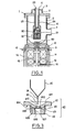
- FIG. 1 there can be seen in the upper part a flange 1, which is surmounted by a cover 3 forming a sulfur hexafluoride tank, middle preferably used in high voltage environments.
- the reservoir and flange b are pierced axially by a support sleeve 4, which is for example made of PLEXIGLAS, and can contain cables for supplying power to the interior of the devices.
- an enclosure 6, internally doubled by a mu-metal shield 5 defines the housing for the field emission cathode and its focusing members.
- the enclosure 6 is pierced with a large orifice 7, which allows its relationship with a very high vacuum generating member, for example an ion pump with sublimation of titanium.
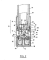
- the sleeve 24 is surrounded by an insulating alumina sheath 25, which only goes as far as the interior of the reservoir 3.
- the sheath 25 forms a "high voltage passage” and at the same time performs vacuum sealing .
- the high voltage 25 used to support passage (fig. 2) firstly to the cathode field emission device 20, the active filament 21 is noted, then the magnetic lens 50, and finally to an intermediate p p electrode Eri heric 70 which surrounds this set.
- the electrons thus produced will exit vertically in the direction of the bottom, and reach the anode 80 (fig.l).
- a fixing support 9 which retains in an adjustable manner in position in particular by screws 15, a condenser assembly formed of a first condenser coil 11 , followed by a second condenser coil 12, after which a device 16 makes it possible to form an adjustable diaphragm.
- This assembly is surrounded by shielding 14.
- the high-voltage passage 25 is extended at the periphery by a thin ring 32, to which is suspended an annular device 30, of somewhat complex shape, since it in turn serves as a support for all the electrical parts. Furthermore, the part 30 comprises a ring 31, which serves as a rotary guide for the introduction of the sleeve 24 and the establishment of electrical contacts.
- the annular part 30 supports by means of an elastic suspension another internal ring 41, which supports an insulating disc 45, vacuum tight, and which in turn serves for the suspension of the cathode 20, via electrical bushing members such as 43 and 44.
- This disc 45 is located opposite a homologous disc 26, placed at the bottom in the PLEXIGLAS sleeve 24, from which it receives the various electrical bushings, such as 40.
- the cathode itself consists of a support base 27, made of insulating material such as alumina.
- This base 27 is in turn provided with electrical bushings, an example of which is seen at 28.
- This bushing is used for auxiliary power supply purposes, as well as to ensure better suspension of the base 27.
- Crossings of the same kind, but placed in a plane perpendicular to the figure support the cathode filament 20, the shape of which is better illustrated in FIG. 3, which is a section in the plane perpendicular to FIG. 2.
- screws such as 42 allow the displacement of the whole of the cathode relative to the support, which makes it possible to precisely adjust the position of the cathode filament 20, which can be done even in operation, by the intermediate Teflon rods such as that illustrated at 23 in FIG. 1.
- the part 30 supports another ring 33, which in turn receives by lower fixing using screws such as 35 an alumina cylinder 34, pierced with orifices such as 36.
- this cylinder receives at 37 the entire magnetic focusing device.
- This assembly comprises, below a metal plate 39, magnetic circuits 53, which internally house a coil 51, in a sealed carcass 52.
- the magnetic circuit is interrupted on the side of the axis of the coil 51 , where the cathode filament 20 arrives.
- the magnetic circuit is defined by a pole piece, in fact consisting of two parts denoted 61 and 62, and held in relative position by a spacer 63, this assembly appearing so more detailed in figure 3.
- the electrical bushing 40 enables the coil to be supplied, as well as the supply of the high voltage to the entire coil device, one of the wires going towards the fixing screw. 38, while the other goes directly to the winding 51.
- the part 33 also has a radial outward shoulder noted 33A, which serves as a support for an intermediate electrode generally designated by 70.
- This electrode is in fact in two parts 71 and 72, which are held in place by screwing one on the other, while enclosing the shoulder 33A.
- the lower part 71 is provided in the lower part with an orifice 73 which is placed on the axis of the coil.
- the pole piece 60 is asymmetrical. Indeed, it comprises an upper pole 61 which is pierced with a hole 610 whose diameter varies from approximately 1.5 to 3 mm preferably. However, larger values can be considered in some cases, as already indicated.
- the upper pole 61 is shrunk to the lower pole 62 by means of a titanium ring 63, and the diameter of the hole 620 in the lower pole is of the order of 5 mm. As previously indicated, slightly different values can be considered.
- the value of the air gap is of the order of a millimeter.
- the air gap is measured here between the lower plane of the upper pole 61 and the upper plane of the lower pole 62.
- axis line 65 which defines the median plane of the pole piece, or of the air gap.
- the upper pole 61 or first part of the pole piece has a concave frustoconical recess 611 which connects with the orifice 610, and allows the cathode filament 20 to be introduced as close as possible to the orifice.
- the cathode filament is considerably enlarged in relation to the size of the pole piece).
- the upper pole 61 comprises a plate 612, which extends radially perpendicular to the axis, and surrounds the orifice 610.
- This plate 612 is followed consecutively by two recesses 613 and 614 which are also flat, but are set back with respect to the other pole 62, and are connected together by an axial cylindrical zone which serves as a support for the ring 63.
- the second pole 62 also includes a plate 621 which extends radially perpendicular to the axis and surrounds the orifice 620. This plate is followed by a recessed area 622 which again ends in a shoulder ensuring the placement of the titanium ring 63.
- the magnetic lens with short focal length, which implies that the proximal end 22 of the axial part 21 of the cathode filament 20 is placed at a distance of approximately 1.5 to 3 mm from the median plane 63 of the air gap of the magnetic lens.
- the present invention makes it possible to obtain low values of the spherical C and chromatic C aberration coefficients, namely of the order of a few millimeters. We were able to obtain for example a coefficient C of 3 mm and a coefficient C of 1.8 mm.
- the electronic probe current is at least 4 times greater than that obtained with the field emission canors and electrostatic lens currently in service, and this for probes with a diameter greater than about 10 nanometers.
- the arrangement proposed according to the present invention also has the advantage of obtaining a priori good stability of the downstream focal point in the lens, that is to say of the electronic image source, which is given from the cathode by the magnetic lens.
- the already mentioned intermediate electrode 70 is provided, which is placed immediately after the magnetic lens, and comes to define at 73 an orifice on the axis of the latter.
- the stability of the position of the electronic image source is considerably increased. If for example the final acceleration voltage is noted V and the extraction voltage of the electrons is V o , the voltage ratio V i / V o can vary from 4 to 50 without the position of the image electronic source varying more than 5 mm along the optical axis.
- the invention can be used in all applications of electron guns, in particular when an intense electronic current is required on a probe diameter less than 0.2mLcrometer. More particularly, the fields of application of the invention are: conventional and scanning electron microscopy, X-ray microanalysis, Auger spectroscopy, and microlithography, in particular.
Landscapes
- Chemical & Material Sciences (AREA)
- Analytical Chemistry (AREA)
- Electron Sources, Ion Sources (AREA)
Applications Claiming Priority (2)
| Application Number | Priority Date | Filing Date | Title |
|---|---|---|---|
| FR8208952 | 1982-05-24 | ||
| FR8208952A FR2527383A1 (fr) | 1982-05-24 | 1982-05-24 | Canon a electrons avec cathode a emission de champ et lentille magnetique |
Publications (2)
| Publication Number | Publication Date |
|---|---|
| EP0095969A1 true EP0095969A1 (de) | 1983-12-07 |
| EP0095969B1 EP0095969B1 (de) | 1988-11-09 |
Family
ID=9274259
Family Applications (1)
| Application Number | Title | Priority Date | Filing Date |
|---|---|---|---|
| EP83401010A Expired EP0095969B1 (de) | 1982-05-24 | 1983-05-20 | Elektronenkanone mit Feldemissionskathode und magnetischer Linse |
Country Status (5)
| Country | Link |
|---|---|
| US (1) | US4544845A (de) |
| EP (1) | EP0095969B1 (de) |
| JP (1) | JPS5942748A (de) |
| DE (1) | DE3378443D1 (de) |
| FR (1) | FR2527383A1 (de) |
Cited By (5)
| Publication number | Priority date | Publication date | Assignee | Title |
|---|---|---|---|---|
| FR2596579A1 (fr) * | 1986-03-25 | 1987-10-02 | Univ Reims Champagne Ardenne | Canon a particules electriques permettant l'emission pulsee de particules d'energie determinee |
| EP0308560A1 (de) * | 1987-09-22 | 1989-03-29 | Universite De Reims Champagne Ardenne | Geladene Teilchenkanone, welche die pulsierte Emission von Teilchen mit einer gewissen Energie erlaubt |
| US4825080A (en) * | 1986-03-25 | 1989-04-25 | Universite De Reims Champagne-Ardenne | Electrical particle gun |
| NL8901517A (nl) * | 1988-06-17 | 1990-01-16 | Hitachi Ltd | Elektronenkanonsysteem met veldemissie. |
| EP0552700A1 (de) * | 1992-01-24 | 1993-07-28 | Etec Systems, Inc. | Mechanisch stabile Feldemissionsquelle |
Families Citing this family (10)
| Publication number | Priority date | Publication date | Assignee | Title |
|---|---|---|---|---|
| US4734158A (en) * | 1987-03-16 | 1988-03-29 | Hughes Aircraft Company | Molecular beam etching system and method |
| JP2775071B2 (ja) * | 1989-02-22 | 1998-07-09 | 日本電信電話株式会社 | 荷電粒子ビーム発生装置 |
| SG74599A1 (en) * | 1997-09-27 | 2000-08-22 | Inst Of Material Res & Enginee | Portable high resolution scanning electron microscope column using permanent magnet electron lenses |
| JP3998556B2 (ja) * | 2002-10-17 | 2007-10-31 | 株式会社東研 | 高分解能x線顕微検査装置 |
| US7218703B2 (en) * | 2003-11-21 | 2007-05-15 | Tohken Co., Ltd. | X-ray microscopic inspection apparatus |
| US7893406B1 (en) * | 2005-06-29 | 2011-02-22 | Hermes-Microvision, Inc. | Electron gun with magnetic immersion double condenser lenses |
| US7427765B2 (en) * | 2005-10-03 | 2008-09-23 | Jeol, Ltd. | Electron beam column for writing shaped electron beams |
| US7476880B2 (en) * | 2005-10-03 | 2009-01-13 | Applied Materials, Inc. | Writing a circuit design pattern with shaped particle beam flashes |
| PL2991095T3 (pl) | 2014-08-25 | 2018-07-31 | MAX-PLANCK-Gesellschaft zur Förderung der Wissenschaften e.V. | Zespół przepustowy wysokiego napięcia, urządzenie do dyfrakcji elektronów i sposób manipulowania urządzeniem elektrodowym w środowisku próżni |
| EP3664121A1 (de) * | 2018-12-05 | 2020-06-10 | ASML Netherlands B.V. | Hochspannungsvakuumdurchführung |
Citations (3)
| Publication number | Priority date | Publication date | Assignee | Title |
|---|---|---|---|---|
| DE857254C (de) * | 1944-08-10 | 1952-11-27 | Siemens Ag | An der Pumpe arbeitender Korpuskularstrahlapparat |
| US3509503A (en) * | 1967-02-27 | 1970-04-28 | Nippon Electron Optics Lab | Objective lens pole pieces |
| US3862419A (en) * | 1972-07-10 | 1975-01-21 | Siemens Ag | Electron-beam illuminating system for an electrical apparatus such as an electron microscope or the like |
Family Cites Families (6)
| Publication number | Priority date | Publication date | Assignee | Title |
|---|---|---|---|---|
| GB697923A (en) * | 1951-03-06 | 1953-09-30 | Ass Elect Ind | Improvements relating to magnetic electron lenses |
| GB1291221A (en) * | 1968-07-07 | 1972-10-04 | Smith Kenneth C A | Electron probe forming system |
| US3678333A (en) * | 1970-06-15 | 1972-07-18 | American Optical Corp | Field emission electron gun utilizing means for protecting the field emission tip from high voltage discharges |
| GB1594465A (en) * | 1977-03-23 | 1981-07-30 | Nat Res Dev | Electron beam apparatus |
| JPS5429075A (en) * | 1977-08-09 | 1979-03-03 | Fujitsu Ltd | Reed switch |
| JPS58123648A (ja) * | 1982-01-18 | 1983-07-22 | Hitachi Ltd | 電磁レンズポ−ルピ−ス構造体 |
-
1982
- 1982-05-24 FR FR8208952A patent/FR2527383A1/fr active Granted
-
1983
- 1983-05-13 US US06/494,574 patent/US4544845A/en not_active Expired - Fee Related
- 1983-05-20 EP EP83401010A patent/EP0095969B1/de not_active Expired
- 1983-05-20 DE DE8383401010T patent/DE3378443D1/de not_active Expired
- 1983-05-24 JP JP58091396A patent/JPS5942748A/ja active Granted
Patent Citations (3)
| Publication number | Priority date | Publication date | Assignee | Title |
|---|---|---|---|---|
| DE857254C (de) * | 1944-08-10 | 1952-11-27 | Siemens Ag | An der Pumpe arbeitender Korpuskularstrahlapparat |
| US3509503A (en) * | 1967-02-27 | 1970-04-28 | Nippon Electron Optics Lab | Objective lens pole pieces |
| US3862419A (en) * | 1972-07-10 | 1975-01-21 | Siemens Ag | Electron-beam illuminating system for an electrical apparatus such as an electron microscope or the like |
Non-Patent Citations (2)
| Title |
|---|
| OPTIK, vol. 57, no. 3, décembre 1980, pages 401-419, Stuttgart, DE. * |
| PROCEEDINGS OF THE SYMPOSIUM ON ELECTRON AND ION BEAM SCIENCE AND TECHNOLOGY, vol. 78-5, 1979, pages 3-9, Princeton, USA * |
Cited By (5)
| Publication number | Priority date | Publication date | Assignee | Title |
|---|---|---|---|---|
| FR2596579A1 (fr) * | 1986-03-25 | 1987-10-02 | Univ Reims Champagne Ardenne | Canon a particules electriques permettant l'emission pulsee de particules d'energie determinee |
| US4825080A (en) * | 1986-03-25 | 1989-04-25 | Universite De Reims Champagne-Ardenne | Electrical particle gun |
| EP0308560A1 (de) * | 1987-09-22 | 1989-03-29 | Universite De Reims Champagne Ardenne | Geladene Teilchenkanone, welche die pulsierte Emission von Teilchen mit einer gewissen Energie erlaubt |
| NL8901517A (nl) * | 1988-06-17 | 1990-01-16 | Hitachi Ltd | Elektronenkanonsysteem met veldemissie. |
| EP0552700A1 (de) * | 1992-01-24 | 1993-07-28 | Etec Systems, Inc. | Mechanisch stabile Feldemissionsquelle |
Also Published As
| Publication number | Publication date |
|---|---|
| JPS5942748A (ja) | 1984-03-09 |
| JPH0341937B2 (de) | 1991-06-25 |
| US4544845A (en) | 1985-10-01 |
| FR2527383A1 (fr) | 1983-11-25 |
| FR2527383B1 (de) | 1985-01-11 |
| EP0095969B1 (de) | 1988-11-09 |
| DE3378443D1 (en) | 1988-12-15 |
Similar Documents
| Publication | Publication Date | Title |
|---|---|---|
| EP0095969B1 (de) | Elektronenkanone mit Feldemissionskathode und magnetischer Linse | |
| EP2195643B1 (de) | System zur analyse eines niederdruckgases mittels optischer emissionsspektroskopie | |
| FR2482768A1 (fr) | Separateur de masses exb pour faisceaux ioniques domines par des charges d'espace | |
| EP0000309B1 (de) | Hohlstrahlgenerator zur Erzeugung von längsschraubenförmigen Bahnen laufenden monokinetischen Elektronen | |
| EP0151078B1 (de) | Lichtstarker Massenspektrometer mit Mehrfach- und Simultanauslesung | |
| EP0209432A1 (de) | Elektronenstrahltester für integrierte Schaltkreise | |
| WO2009027596A2 (fr) | Source micronique d'émission ionique | |
| US20170229276A1 (en) | High voltage feedthrough assembly, time-resolved transmission electron microscope and method of electrode manipulation in a vacuum environment | |
| BE433386A (de) | ||
| EP0254625B1 (de) | Verfahren und Vorrichtung zur Entladung nichtleitender Proben während einer Ionenstrahl-Analyse | |
| EP2198449A1 (de) | Hochauflösende tomografische weitwinkelsonde | |
| CA2576774A1 (fr) | Piege a ions a aimant permanent longitudinal et spectrometre de masse utilisant un tel aimant | |
| EP2396806B1 (de) | Massenanalyseeinrichtung mit grosser winkelannahmefähigkeit mit einem reflektron | |
| FR2644930A1 (fr) | Lentille electromagnetique composite a focale variable | |
| FR2814853A1 (fr) | Scintillateur compact a haut rendement de collecte pour la detection d'electrons secondaires | |
| FR2460080A1 (fr) | Tube de camera de television a focalisation electrostatique | |
| EP0115731A2 (de) | Abtaströntgenröhre | |
| US4367427A (en) | Glow discharge lamp for qualitative and quantitative spectrum analysis | |
| FR2551264A1 (fr) | Tube a rayons cathodiques | |
| EP1490888B1 (de) | Einrichtung zur messung der emission von röntgenstrahlen, die durch ein objekt erzeugt werden, das einem elektronenstrahl ausgesetzt ist | |
| EP0449740A1 (de) | Vorrichtung zur Fokussierung eines geladenen Teilchenstrahls | |
| EP0308560A1 (de) | Geladene Teilchenkanone, welche die pulsierte Emission von Teilchen mit einer gewissen Energie erlaubt | |
| FR2596579A1 (fr) | Canon a particules electriques permettant l'emission pulsee de particules d'energie determinee | |
| Burstert et al. | Novel high brightness miniature electron gun for high current e-beam applications | |
| FR2763469A1 (fr) | Element de circuit electrique ou electronique exempt de phenomene de micro-decharges |
Legal Events
| Date | Code | Title | Description |
|---|---|---|---|
| PUAI | Public reference made under article 153(3) epc to a published international application that has entered the european phase |
Free format text: ORIGINAL CODE: 0009012 |
|
| AK | Designated contracting states |
Designated state(s): DE GB NL |
|
| 17P | Request for examination filed |
Effective date: 19831214 |
|
| GRAA | (expected) grant |
Free format text: ORIGINAL CODE: 0009210 |
|
| AK | Designated contracting states |
Kind code of ref document: B1 Designated state(s): DE GB NL |
|
| GBT | Gb: translation of ep patent filed (gb section 77(6)(a)/1977) | ||
| REF | Corresponds to: |
Ref document number: 3378443 Country of ref document: DE Date of ref document: 19881215 |
|
| PLBE | No opposition filed within time limit |
Free format text: ORIGINAL CODE: 0009261 |
|
| STAA | Information on the status of an ep patent application or granted ep patent |
Free format text: STATUS: NO OPPOSITION FILED WITHIN TIME LIMIT |
|
| 26N | No opposition filed | ||
| PGFP | Annual fee paid to national office [announced via postgrant information from national office to epo] |
Ref country code: GB Payment date: 19950512 Year of fee payment: 13 |
|
| PGFP | Annual fee paid to national office [announced via postgrant information from national office to epo] |
Ref country code: DE Payment date: 19950524 Year of fee payment: 13 |
|
| PGFP | Annual fee paid to national office [announced via postgrant information from national office to epo] |
Ref country code: NL Payment date: 19950531 Year of fee payment: 13 |
|
| PG25 | Lapsed in a contracting state [announced via postgrant information from national office to epo] |
Ref country code: GB Effective date: 19960520 |
|
| PG25 | Lapsed in a contracting state [announced via postgrant information from national office to epo] |
Ref country code: NL Effective date: 19961201 |
|
| GBPC | Gb: european patent ceased through non-payment of renewal fee |
Effective date: 19960520 |
|
| PG25 | Lapsed in a contracting state [announced via postgrant information from national office to epo] |
Ref country code: DE Effective date: 19970201 |
|
| NLV4 | Nl: lapsed or anulled due to non-payment of the annual fee |
Effective date: 19961201 |