EP0095977B1 - Fahrbare Betonzentrale mit einer Vorrichtung zur Entnahme von Zement - Google Patents
Fahrbare Betonzentrale mit einer Vorrichtung zur Entnahme von Zement Download PDFInfo
- Publication number
- EP0095977B1 EP0095977B1 EP83401057A EP83401057A EP0095977B1 EP 0095977 B1 EP0095977 B1 EP 0095977B1 EP 83401057 A EP83401057 A EP 83401057A EP 83401057 A EP83401057 A EP 83401057A EP 0095977 B1 EP0095977 B1 EP 0095977B1
- Authority
- EP
- European Patent Office
- Prior art keywords
- screw
- silo
- concrete plant
- mobile concrete
- extracting
- Prior art date
- Legal status (The legal status is an assumption and is not a legal conclusion. Google has not performed a legal analysis and makes no representation as to the accuracy of the status listed.)
- Expired
Links
- 239000004568 cement Substances 0.000 title claims abstract description 25
- 238000000605 extraction Methods 0.000 title claims abstract description 10
- XLYOFNOQVPJJNP-UHFFFAOYSA-N water Substances O XLYOFNOQVPJJNP-UHFFFAOYSA-N 0.000 claims abstract description 4
- 230000003028 elevating effect Effects 0.000 description 7
- 238000005303 weighing Methods 0.000 description 5
- 238000010276 construction Methods 0.000 description 4
- 210000000481 breast Anatomy 0.000 description 3
- 239000000463 material Substances 0.000 description 3
- 230000005465 channeling Effects 0.000 description 2
- 238000004519 manufacturing process Methods 0.000 description 2
- 229910000831 Steel Inorganic materials 0.000 description 1
- 230000002159 abnormal effect Effects 0.000 description 1
- 230000000694 effects Effects 0.000 description 1
- 239000000284 extract Substances 0.000 description 1
- 230000005484 gravity Effects 0.000 description 1
- 230000001788 irregular Effects 0.000 description 1
- 238000012423 maintenance Methods 0.000 description 1
- 210000002445 nipple Anatomy 0.000 description 1
- 239000004576 sand Substances 0.000 description 1
- 239000010959 steel Substances 0.000 description 1
Images

Classifications
-
- B—PERFORMING OPERATIONS; TRANSPORTING
- B28—WORKING CEMENT, CLAY, OR STONE
- B28C—PREPARING CLAY; PRODUCING MIXTURES CONTAINING CLAY OR CEMENTITIOUS MATERIAL, e.g. PLASTER
- B28C9/00—General arrangement or layout of plant
- B28C9/04—General arrangement or layout of plant the plant being mobile, e.g. mounted on a carriage or a set of carriages
-
- B—PERFORMING OPERATIONS; TRANSPORTING
- B28—WORKING CEMENT, CLAY, OR STONE
- B28C—PREPARING CLAY; PRODUCING MIXTURES CONTAINING CLAY OR CEMENTITIOUS MATERIAL, e.g. PLASTER
- B28C7/00—Controlling the operation of apparatus for producing mixtures of clay or cement with other substances; Supplying or proportioning the ingredients for mixing clay or cement with other substances; Discharging the mixture
- B28C7/04—Supplying or proportioning the ingredients
- B28C7/06—Supplying the solid ingredients, e.g. by means of endless conveyors or jigging conveyors
- B28C7/10—Supplying the solid ingredients, e.g. by means of endless conveyors or jigging conveyors by means of rotary members, e.g. inclinable screws
Definitions
- the present invention relates to the manufacture of concrete on construction sites, and more particularly to an improved mobile concrete plant.
- the usual type concrete plants for example M50 from the company 'BURTON' STEEL, generally include a cement extraction device consisting of an integrated silo, equipped with a system of extracting screws and elevating screws bringing the cement to a weighing device, for example a scale, then to a mixer, which also leads to an aggregate, sand and pebble extraction device, by a mobile conveyor completed by a hopper and a second weighing device, for example a weighing belt.
- a cement extraction device consisting of an integrated silo, equipped with a system of extracting screws and elevating screws bringing the cement to a weighing device, for example a scale, then to a mixer, which also leads to an aggregate, sand and pebble extraction device, by a mobile conveyor completed by a hopper and a second weighing device, for example a weighing belt.
- the integrated cement silo occupies an inclined position along a slope of approximately 15 ° to limit its size, and generally comprises two parallel udders which channel the cement over the entire length.
- an extractor screw In the bottom of each udder having the shape of a trough, is placed an extractor screw bringing back the cement to the rear of the silo from where it is extracted by two elevating screws placed on either side of the extractor screws.
- These two tubular lifting screws pass through the silo over its entire length and bring the cement up to a scale from where it is poured into the mixer.
- This device makes it possible to produce a relatively compact mobile concrete plant, but has drawbacks. Indeed the slopes of the udders do not allow a regular flow of the cement, and consequently the feeding of the extracting screws is irregular and it forms many "dead heaps". In addition, the concentration of cement in the rear part of the silo and the lack of channeling towards the two elevating screws cause an overload of these which causes an abnormal increase in intensity in the gearmotors which frequently trip.
- US-A-3,945,619 describes a concrete plant with several elevating screws arranged in cascade. the first of which is placed at the highest end of the extractor screw; FR-A-2,417,451 relates to a worm conveyor comprising a horizontal screw and a vertical screw communicating with each other at their respective ends; US-A-4,219,279 describes a mobile material mixer in which the material passes from the extractor screw to the lifting screw via a conveyor belt.
- the present invention relates to a mobile concrete batching plant of the above type, comprising a cement extraction device with a single extracting screw and a single lifting screw.
- a more particular subject of the invention is a mobile concrete plant, the construction of which is simpler and the operation more efficient than conventional plants.
- the mobile concrete batching plant in accordance with the present invention is of the type comprising a mixer which leads to an aggregate supply device, a water inlet, and a cement extraction device comprising a silo with an inclined trough bottom. along its longitudinal axis, V-section, an extractor screw placed in the trough, and an elevating screw; the extractor screw is a double-effect screw, the elevating screw, inclined at an angle of 30 to 70 ° relative to the horizontal, crosses the silo near the extractor screw, and the two screws communicate by a low neck length, the pitch of the turns of the extractor screw reversing at the level of the communication neck.
- the inclination of the extraction device constituting a cement silo, in the operating position is approximately 10 to 20 ° relative to the horizontal, and preferably approximately 15 °.
- the trough-shaped silo has a bottom, the cross section of which is V-shaped, the inclination of each plane relative to the horizontal being between 40 and 60 °, and preferably equal to approximately 50 °.
- the trough of the extractor screw and the tube of the elevator screw communicate by a neck of short length oriented downwards, from the extractor screw to the elevator screw, located approximately 2/3 of the length of the silo from its lower end.
- This position can vary and be modified if necessary by the technician depending on the inclination of the silo and the nature of the cement. It is generally preferable that this communication bottleneck is located in the upper part of the silo, near its middle.
- the extractor screw located at the bottom of the trough is a double-acting screw: the turns located above the communication neck have a pitch to the left while the turns located below the neck have a step to the right, so that the rotary movement of the extractor screw has a driving effect of the cement contained in the silo, towards the neck of communication with the elevating screw, that is to say that the cement in the upper part is brought down, while the cement in the lower part is pushed up.
- the operation of the screws is adjusted so that the flow rate of the extractor screw is greater than the flow rate of the lifting screw.
- the diameter of the extractor screw can be between 200 and 300mm, the pitch of the turns being between 150 and 200mm in the upper part, and between 170 and 230mm in the lower part.
- the diameter of the lifting screw can be between 200 and 300mm, the pitch of the turns being of the order of 150 to 250mm.
- the inclination of the lifting screw is determined according to the operating conditions and the structure of the concrete plant. It can be between 30 and 70 ° relative to the horizontal, and preferably between 50 and 60 °.
- the device according to the present invention provides an operation of good efficiency, in particular at the level of the feeding of the lifting screw, while reducing the material necessary for its construction, which reduces its manufacturing cost and improves its profitability. In addition, maintenance is facilitated, and the reliability of the device is improved.
- the whole silo, mixer, cement scale and other accessories such as the aggregate weighing belt, the water supply and weighing device, can be mounted on a mobile machine that can be moved to the construction site.
- the silo (1) is inclined at a slope of about 15 ° from the horizontal.
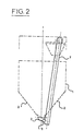
- the bottom of this silo (1) has the shape of a V constituted by the two inclined planes (2) whose slope with respect to the horizontal is about 50 ° (cf. fig. 2).
- a double-acting extractor screw (4) In the trough bottom (3) of the silo (1) is placed a double-acting extractor screw (4), supported by the intermediate bearing (5) and driven by a motor (not shown) placed at the end of the axis at its the top part.
- It may for example be a motor with a power of the order of 11 kW (15 hp), driving the screw in a rotational movement of 65 revolutions / min, or a flow rate of 65 t / h, in the case of a 250mm diameter extractor screw with turns having a pitch of 170mm on the left in the upper part of the silo, and a pitch of 200mm on the right in the lower part.
- the silo (1) is crossed in its upper part by a lifting screw (6) placed in a tube (7) which communicates with the trough (3) of the extracting screw (4) by the neck (8) located approximately at 2/3 of the length of the silo from the bottom end.
- the screw (6) extracts the cement contained in the silo (1) and pours it into the cement scale (9) from where it is then poured into a conventional type mixer (not shown).
- the lifting screw (6) is driven by a 7.36 kW (10 hp) motor, for example, giving it a rotation speed of 167 rpm, corresponding to a flow rate of 60 t / h for a screw 250 mm in diameter having turns whose pitch is 200mm.
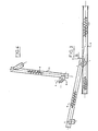
- Figures 3 and 4 show in more detail the extractor screw (4) in its trough (3), and the lifting screw (6) and the neck (8) connecting between the two screws.
- the cement in the silo (1) is brought back by the double-acting extractor screw (4) towards the neck (8) where it falls by gravity onto the lifting screw (6) which rises it towards the scale.
Landscapes
- Chemical & Material Sciences (AREA)
- Dispersion Chemistry (AREA)
- Preparation Of Clay, And Manufacture Of Mixtures Containing Clay Or Cement (AREA)
- Artificial Fish Reefs (AREA)
- Bulkheads Adapted To Foundation Construction (AREA)
- Curing Cements, Concrete, And Artificial Stone (AREA)
- Processing Of Solid Wastes (AREA)
- Mixers Of The Rotary Stirring Type (AREA)
Claims (7)
Priority Applications (1)
| Application Number | Priority Date | Filing Date | Title |
|---|---|---|---|
| AT83401057T ATE39078T1 (de) | 1982-05-27 | 1983-05-26 | Fahrbare betonzentrale mit einer vorrichtung zur entnahme von zement. |
Applications Claiming Priority (2)
| Application Number | Priority Date | Filing Date | Title |
|---|---|---|---|
| FR8209218 | 1982-05-27 | ||
| FR8209218A FR2527504B1 (fr) | 1982-05-27 | 1982-05-27 | Centrale a beton mobile comportant un dispositif perfectionne d'extraction du ciment |
Publications (3)
| Publication Number | Publication Date |
|---|---|
| EP0095977A2 EP0095977A2 (de) | 1983-12-07 |
| EP0095977A3 EP0095977A3 (en) | 1984-06-06 |
| EP0095977B1 true EP0095977B1 (de) | 1988-12-07 |
Family
ID=9274386
Family Applications (1)
| Application Number | Title | Priority Date | Filing Date |
|---|---|---|---|
| EP83401057A Expired EP0095977B1 (de) | 1982-05-27 | 1983-05-26 | Fahrbare Betonzentrale mit einer Vorrichtung zur Entnahme von Zement |
Country Status (5)
| Country | Link |
|---|---|
| EP (1) | EP0095977B1 (de) |
| AT (1) | ATE39078T1 (de) |
| DE (1) | DE3378619D1 (de) |
| FR (1) | FR2527504B1 (de) |
| PT (1) | PT76771B (de) |
Families Citing this family (3)
| Publication number | Priority date | Publication date | Assignee | Title |
|---|---|---|---|---|
| CH679999A5 (de) * | 1989-11-22 | 1992-05-29 | Adelrich Spescha | |
| GB2258412A (en) * | 1991-06-29 | 1993-02-10 | Electrical Services | Slurry containers |
| CN113277337B (zh) * | 2021-06-10 | 2024-11-19 | 平顶山市安泰华矿用安全设备制造有限公司 | 煤渣计量上料装置 |
Family Cites Families (5)
| Publication number | Priority date | Publication date | Assignee | Title |
|---|---|---|---|---|
| DE2152623C3 (de) * | 1971-10-22 | 1975-03-27 | Eugen Dietterle Kg, Gips- Und Saegewerk, 7031 Gueltstein | Vorrichtung zum kontinuierlichen Mischen und Verspritzen von Putzmörtel |
| US3945619A (en) * | 1975-03-03 | 1976-03-23 | Taibi Frank P | Mobile continuous concrete proportioning plant |
| US4144655A (en) * | 1976-08-30 | 1979-03-20 | Harris And Thrush Manufacturing Company | Portable storage bin |
| IT1161952B (it) * | 1978-02-15 | 1987-03-18 | Marchesini Wainer | Trasportatore a colclea verticale o molto ripida e a coclea di alimentazione orizzontale |
| US4219279A (en) * | 1979-03-26 | 1980-08-26 | Haws Paul M | Mobile gunnite material mixer |
-
1982
- 1982-05-27 FR FR8209218A patent/FR2527504B1/fr not_active Expired
-
1983
- 1983-05-26 EP EP83401057A patent/EP0095977B1/de not_active Expired
- 1983-05-26 PT PT76771A patent/PT76771B/pt unknown
- 1983-05-26 DE DE8383401057T patent/DE3378619D1/de not_active Expired
- 1983-05-26 AT AT83401057T patent/ATE39078T1/de active
Also Published As
| Publication number | Publication date |
|---|---|
| EP0095977A2 (de) | 1983-12-07 |
| PT76771A (fr) | 1983-06-01 |
| ATE39078T1 (de) | 1988-12-15 |
| FR2527504A1 (fr) | 1983-12-02 |
| PT76771B (fr) | 1986-01-27 |
| DE3378619D1 (en) | 1989-01-12 |
| EP0095977A3 (en) | 1984-06-06 |
| FR2527504B1 (fr) | 1987-04-24 |
Similar Documents
| Publication | Publication Date | Title |
|---|---|---|
| FR2556925A1 (fr) | Machine pour la recolte de la fleur de camomille | |
| FR2564370A1 (fr) | Appareil permettant d'arrondir la circonference d'un troncon de bois | |
| EP0095977A2 (de) | Fahrbare Betonzentrale mit einer Vorrichtung zur Entnahme von Zement | |
| FR2496392A1 (fr) | Procede et dispositif pour le traitement d'espaces verts et en particulier de pelouses | |
| EP0078217B1 (de) | Landwirtschaftliche Maschine, insbesondere Mäher, zum Mähen und/oder Sammeln von Pflanzenpartikeln | |
| FR2866527A1 (fr) | Table de tri pour la vendange | |
| FR2540334A1 (fr) | Moissonneuse-batteuse automotrice a dispositif de nettoyage | |
| FR2626202A1 (fr) | Table pour le triage de la vendange | |
| FR2476438A1 (fr) | Machine a fabriquer et separer de la caillebotte | |
| FR2480069A1 (fr) | Machine et procede pour moissonner des herbes | |
| FR2666252A2 (fr) | Trieur mobile surbaisse avec table de secouage et brosse vis pour le calibrage des pois fourragers et des cereales. | |
| FR2594338A1 (fr) | Autoclave de sterilisation avec dispositif de ruissellement | |
| FR2651088A1 (fr) | Batteur notamment pour moissonneuse-batteuses. | |
| EP0060795B1 (de) | Käsetrog mit Vorrichtung zum Rühren und Zerteilen von eingedickter Milch | |
| EP0018876B1 (de) | Vorrichtung zum Lagern und Abtragen von Schüttguthalden | |
| FR2511835A1 (fr) | Remorque pour le transport pendant leur travail de vendangeurs-coupeurs | |
| FR2527899A1 (fr) | Dispositif d'introduction pour moissonneuse-batteuse a ecoulement axial | |
| FR2632827A1 (fr) | Dispositif pour melanger et broyer des aliments pour animaux | |
| FR2524843A1 (fr) | Procede et dispositif permettant d'obtenir des bandes a partir d'un materiau, notamment un caoutchouc; bandes ainsi obtenues | |
| RU2054273C1 (ru) | Устройство для мойки корнеклубнеплодов | |
| FR2527179A1 (fr) | Silo a chambre de melange pour matieres en vrac | |
| FR2648669A1 (fr) | Perfectionnements apportes aux desileuses a tambour rotatif | |
| FR2484966A1 (fr) | Epandeur directionnel par effet centrifuge de produit en grains mineral, synthetique, vegetal ou animal tel que des huitres | |
| FR2651754A1 (fr) | Dispositif favorisant l'ecoulement de produits en vrac a des pentes faibles, en particulier pour tremies ou silos. | |
| FR2624337A1 (en) | Device which can be fitted to a conventional combine harvester intended to allow easy harvest of tall plants, (colza for example) |
Legal Events
| Date | Code | Title | Description |
|---|---|---|---|
| PUAI | Public reference made under article 153(3) epc to a published international application that has entered the european phase |
Free format text: ORIGINAL CODE: 0009012 |
|
| AK | Designated contracting states |
Designated state(s): AT BE CH DE GB IT LI LU NL SE |
|
| PUAL | Search report despatched |
Free format text: ORIGINAL CODE: 0009013 |
|
| AK | Designated contracting states |
Designated state(s): AT BE CH DE GB IT LI LU NL SE |
|
| 17P | Request for examination filed |
Effective date: 19841110 |
|
| 17Q | First examination report despatched |
Effective date: 19860703 |
|
| GRAA | (expected) grant |
Free format text: ORIGINAL CODE: 0009210 |
|
| AK | Designated contracting states |
Kind code of ref document: B1 Designated state(s): AT BE CH DE GB IT LI LU NL SE |
|
| PG25 | Lapsed in a contracting state [announced via postgrant information from national office to epo] |
Ref country code: SE Effective date: 19881207 Ref country code: NL Effective date: 19881207 Ref country code: IT Free format text: LAPSE BECAUSE OF FAILURE TO SUBMIT A TRANSLATION OF THE DESCRIPTION OR TO PAY THE FEE WITHIN THE PRESCRIBED TIME-LIMIT;WARNING: LAPSES OF ITALIAN PATENTS WITH EFFECTIVE DATE BEFORE 2007 MAY HAVE OCCURRED AT ANY TIME BEFORE 2007. THE CORRECT EFFECTIVE DATE MAY BE DIFFERENT FROM THE ONE RECORDED. Effective date: 19881207 Ref country code: AT Effective date: 19881207 |
|
| REF | Corresponds to: |
Ref document number: 39078 Country of ref document: AT Date of ref document: 19881215 Kind code of ref document: T |
|
| GBT | Gb: translation of ep patent filed (gb section 77(6)(a)/1977) | ||
| REF | Corresponds to: |
Ref document number: 3378619 Country of ref document: DE Date of ref document: 19890112 |
|
| NLV1 | Nl: lapsed or annulled due to failure to fulfill the requirements of art. 29p and 29m of the patents act | ||
| PG25 | Lapsed in a contracting state [announced via postgrant information from national office to epo] |
Ref country code: LU Free format text: LAPSE BECAUSE OF NON-PAYMENT OF DUE FEES Effective date: 19890531 Ref country code: LI Effective date: 19890531 Ref country code: CH Effective date: 19890531 Ref country code: BE Effective date: 19890531 |
|
| PLBE | No opposition filed within time limit |
Free format text: ORIGINAL CODE: 0009261 |
|
| STAA | Information on the status of an ep patent application or granted ep patent |
Free format text: STATUS: NO OPPOSITION FILED WITHIN TIME LIMIT |
|
| 26N | No opposition filed | ||
| REG | Reference to a national code |
Ref country code: CH Ref legal event code: PL |
|
| PGFP | Annual fee paid to national office [announced via postgrant information from national office to epo] |
Ref country code: GB Payment date: 19960517 Year of fee payment: 14 |
|
| PGFP | Annual fee paid to national office [announced via postgrant information from national office to epo] |
Ref country code: DE Payment date: 19960628 Year of fee payment: 14 |
|
| PG25 | Lapsed in a contracting state [announced via postgrant information from national office to epo] |
Ref country code: GB Effective date: 19970526 |
|
| GBPC | Gb: european patent ceased through non-payment of renewal fee |
Effective date: 19970526 |
|
| PG25 | Lapsed in a contracting state [announced via postgrant information from national office to epo] |
Ref country code: DE Free format text: LAPSE BECAUSE OF NON-PAYMENT OF DUE FEES Effective date: 19980203 |
|
| P01 | Opt-out of the competence of the unified patent court (upc) registered |
Effective date: 20230522 |