EP0095988A1 - Türschloss, insbesondere für Kraftfahrzeuge - Google Patents
Türschloss, insbesondere für Kraftfahrzeuge Download PDFInfo
- Publication number
- EP0095988A1 EP0095988A1 EP83401123A EP83401123A EP0095988A1 EP 0095988 A1 EP0095988 A1 EP 0095988A1 EP 83401123 A EP83401123 A EP 83401123A EP 83401123 A EP83401123 A EP 83401123A EP 0095988 A1 EP0095988 A1 EP 0095988A1
- Authority
- EP
- European Patent Office
- Prior art keywords
- bolt
- lever
- lock
- hand
- locking member
- Prior art date
- Legal status (The legal status is an assumption and is not a legal conclusion. Google has not performed a legal analysis and makes no representation as to the accuracy of the status listed.)
- Granted
Links
Images



Classifications
-
- E—FIXED CONSTRUCTIONS
- E05—LOCKS; KEYS; WINDOW OR DOOR FITTINGS; SAFES
- E05B—LOCKS; ACCESSORIES THEREFOR; HANDCUFFS
- E05B81/00—Power-actuated vehicle locks
- E05B81/12—Power-actuated vehicle locks characterised by the function or purpose of the powered actuators
- E05B81/20—Power-actuated vehicle locks characterised by the function or purpose of the powered actuators for assisting final closing or for initiating opening
Definitions
- the present invention relates to door locks, in particular for a motor vehicle, of the type comprising a bolt and a keeper movable relative to one another so as to be able to hang on or free from each other when the blocking or unlocking of the lock, the bolt being associated with a locking member which is intended to retain the bolt in its position hooked on the strike and which is controlled by motor means intended to release it from the bolt against an elastic return member of this locking member, said motor means being further coupled to the bolt by a transmission to bring the bolt into its hooked position during the final phase of blocking the lock.
- the weight gain sought by all manufacturers to reduce energy consumption results in a reduction in the mass of the doors, which reduces the inertia forces due to slamming of the door and therefore results in less good compression of the seal, accentuating the faults mentioned above.
- Locks have already been developed capable of automatically closing a car trunk lid in the final phase of its movement. Such locks are described in particular in patents US-A-3,378,291 and US-A-2,950,138.
- the invention aims to remedy these drawbacks.
- a lock of the type indicated above which is characterized in that the bolt and the locking member are both articulated on the housing containing the lock mechanism and in that said motor means comprise a locking member.
- 'drive which is arranged to act separately and successively on the one hand on said locking member when unlocking the lock and on the other hand on said transmission for blocking thereof.
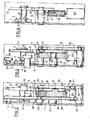
- the lock according to the invention comprises a housing 1 which has in section roughly the shape of a U and in which is housed a bolt 2 mounted articulated around a pin 3 fixed on the bottom of the case. It should be noted that on all F ig., The cover of the housing 1 has not been shown.
- the bolt 2 generally has a triangular shape, one of the vertices of which is articulated on the pin 3 and which, opposite this vertex, has a notch 4 delimiting on the bolt two branches 5 and 6 located on either side of this notch.
- the branch 6 is provided with a heel 7 which extends beyond the outline of the triangle formed by the bolt 2. This same branch 6 carries a locking lug 8.
- a passage 9 which widens towards the side of the housing and in which is intended to penetrate a keeper 10 to be retained in the notch 4 of the bolt when the latter is in its locking position of the lock.
- the bolt 2 cooperates with locking means 11 which firstly comprise a locking lever 12 generally having the shape of an S.
- This lever is articulated on a pin 13 fixed in the housing and has a first locking branch 14 proper, intended to cooperate with the lug 8 of the bolt and comprising two adjacent notches 15 and 16, one 15 called “first notch” and the other 16 called “second notch”.
- the first branch of the locking lever 12 is extended by a connecting portion 17 extending at approximately right angles to this branch and which connects the latter to a second branch 18 for actuating this locking lever.
- This second branch extends approximately at right angles to the connection portion, but in the opposite direction with respect to the first branch, the connection zone being crossed by the articulation pin 13.
- an actuating tab 19 which is folded laterally relative to the general plane of the lever 12 and whose function is essentially to ensure the possibility of opening of backup of the lock as will be explained later.
- the locking means 11 also comprise a toothed wheel 20 rotatably mounted on a pin 21 fixed in the housing, this wheel meshing with an endless screw 22 which is coupled to the shaft of an electric drive motor 23.
- This wheel is provided with a profiled boss 24 forming a pusher which is in the form of a projection raised on one of the faces of the wheel.
- This boss is intended to cooperate, during the rotation of the wheel 20, with an operating lever 25 which is articulated around a pin 26 fixed on the bottom of the housing 1.
- This lever bears at its opposite end with respect to the spindle 26, a roller 27 with which the boss 24 can come into contact during part of its path traveled during the rotation of the wheel 20.
- the operating lever 25 has a lateral wing 28, the outer edge of which forms a cam track 29 constitutes by a notch-shaped part with a rounded bottom to which a projection also with a rounded shape is adjacent.
- the cam track 29 cooperates with a roller 31 which is carried by a transmission lever 30 articulated on the bottom of the housing by means of a pin 3 2 .
- the transmission lever has approximately the shape of an L and is articulated around the pin 32 approximately in the middle of the large branch of this L.
- the small branch of the transmission lever 30 carries at its free end a another roller 33 which is intended to come into contact with the heel 7 of the bolt 2 during the operation of the lock.
- rollers 27, 31 and 33 are mounted to rotate on the corresponding levers respectively by means of pivots 34, 35 and 36.
- the lever 25 is permanently biased towards a fixed stop 37 which is integral with the housing 1, under the action of a spring 38 via a part of the transmission lever 30, resting on its turn by the roller 31 on this lever 25.
- the spring 38 of the helical type is mounted around the spindle 32 and is hooked on the one hand at 39 on the housing 1 and on the other hand at 40 on the corresponding branch of the lever 30.
- the locking lever 12 is provided with a helical spring 41 which is mounted around the spindle 13 and which is hooked by one of its ends on this lever and which by its other end bears against a wall side of the housing 1.
- the locking lever 12 is biased clockwise, as seen in Fig.l and 5 A to 5 D.
- a third floating spring 42 mounted is associated with the bolt 2 to urge it in the direction of the opening of the lock, this spring being hung on the one hand on a side wall of the housing 1 and on the other hand in the edge lateral of the bolt 2, respectively in points 43 and 44.
- the electric motor 23 is mounted in a supply circuit connected to a voltage source (not shown) which can be the vehicle battery.
- a voltage source (not shown) which can be the vehicle battery.
- This motor is mounted in series with a first switch 45 which is fixedly mounted in the housing and which is provided with a feeler 46 placed on the path of the boss 24 of the wheel 20.
- the movable contact of this switch is placed in a position corresponding to the locking of the lock and this position is called “position 1" in the following description, its opposite position being called “O".
- the electric motor 23 is also mounted in series with another switch 47 fixed in the housing and the movable contact of which is provided with a feeler 48 which is intended to be actuated by the edge of the bolt 2 when the latter is in the position corresponding to the "first notch".
- a feeler 48 which is intended to be actuated by the edge of the bolt 2 when the latter is in the position corresponding to the "first notch".
- the lock can be controlled by a device making it possible to actuate the lock both from inside and from outside the vehicle.
- the bolt 2 is in its high position in which on the one hand, the locking pin 8 is released from the notches 15 and 16 of the locking lever 12 and on the other hand, the roller 33 is supported in the rounded portion of the heel 7 of the bolt 2.
- the transmission lever 30 urged by the spring 38 presses the operating lever 25 against the fixed stop 37 of the housing.
- FIG. 6C The corresponding electrical diagram appears in FIG. 6C and it can be seen that in this configuration, the switch 45 having flipped, the motor 23 is short-circuited and therefore stops suddenly. The wheel 20 then rotated for half a turn. The locking pin is pressed into the second notch "of the locking lever and the lock is in its locked position which appears in Fig.5D.
- the wheel 20 returns to its initial opening position shown in FIG. 5A when the bolt has again actuated the switch 47 (position "0").
- the lock just described can be provided with means intended to allow an emergency opening of the door in the event that the supply voltage disappears.
- the locking lever comprises the tab 19 which can be coupled to a linkage provided with a mechanical control button appearing for example on the interior panel of the door.
- this button makes it possible to tilt the locking lever 12 around its axis by releasing the locking pin 8, the bolt 2 and consequently the keeper 10, the movement being recalled by the spring 41.
Landscapes
- Lock And Its Accessories (AREA)
Applications Claiming Priority (2)
| Application Number | Priority Date | Filing Date | Title |
|---|---|---|---|
| FR8209598A FR2528096B1 (fr) | 1982-06-02 | 1982-06-02 | Serrure de portiere, notamment pour vehicule automobile, comportant un pene pivotant associe a un dispositif moteur |
| FR8209598 | 1982-06-02 |
Publications (2)
| Publication Number | Publication Date |
|---|---|
| EP0095988A1 true EP0095988A1 (de) | 1983-12-07 |
| EP0095988B1 EP0095988B1 (de) | 1985-12-27 |
Family
ID=9274561
Family Applications (1)
| Application Number | Title | Priority Date | Filing Date |
|---|---|---|---|
| EP19830401123 Expired EP0095988B1 (de) | 1982-06-02 | 1983-06-02 | Türschloss, insbesondere für Kraftfahrzeuge |
Country Status (4)
| Country | Link |
|---|---|
| EP (1) | EP0095988B1 (de) |
| DE (1) | DE3361626D1 (de) |
| ES (1) | ES523223A0 (de) |
| FR (1) | FR2528096B1 (de) |
Cited By (8)
| Publication number | Priority date | Publication date | Assignee | Title |
|---|---|---|---|---|
| FR2561295A1 (fr) * | 1984-03-19 | 1985-09-20 | Daimler Benz Ag | Serrure de porte, de capot ou analogue pour vehicule automobile, comportant un systeme auxiliaire de fermeture entraine par un moteur |
| FR2606448A1 (fr) * | 1986-10-17 | 1988-05-13 | Roltra Spa | Serrure actionnee electriquement pour vehicule |
| EP0302642A1 (de) * | 1987-08-07 | 1989-02-08 | Rockwell Automotive Body Systems (U.K.) Limited | Kraftfahrzeugtürverschluss |
| EP0267423A3 (en) * | 1986-10-06 | 1989-08-09 | Aisin Seiki Kabushiki Kaisha | Door lock assembly for automotive vehicles |
| WO1998042939A1 (de) * | 1997-03-20 | 1998-10-01 | Robert Bosch Gmbh | Schaltungsanordnung zur steuerung eines elektrisch betätigten kraftfahrzeug-türschlosses o. dgl. |
| EP0942123A1 (de) * | 1998-02-27 | 1999-09-15 | Volkswagen Aktiengesellschaft | Vorrichtung zum Verriegeln einer Abdeckung nach Art einer Karosseriehaube eines Kraftfahrzeugs |
| WO2000000710A3 (en) * | 1998-06-26 | 2000-02-10 | Delphi Tech Inc | Vehicle door latch with cinching mechanism |
| WO2007062635A3 (de) * | 2005-11-30 | 2007-08-23 | Edscha Ag | Verriegelungseinheit |
Citations (2)
| Publication number | Priority date | Publication date | Assignee | Title |
|---|---|---|---|---|
| US2950138A (en) * | 1958-06-30 | 1960-08-23 | Gen Motors Corp | Closure latch |
| US3378291A (en) * | 1966-04-25 | 1968-04-16 | Gen Motors Corp | Closure latch |
-
1982
- 1982-06-02 FR FR8209598A patent/FR2528096B1/fr not_active Expired
-
1983
- 1983-06-01 ES ES523223A patent/ES523223A0/es active Granted
- 1983-06-02 DE DE8383401123T patent/DE3361626D1/de not_active Expired
- 1983-06-02 EP EP19830401123 patent/EP0095988B1/de not_active Expired
Patent Citations (2)
| Publication number | Priority date | Publication date | Assignee | Title |
|---|---|---|---|---|
| US2950138A (en) * | 1958-06-30 | 1960-08-23 | Gen Motors Corp | Closure latch |
| US3378291A (en) * | 1966-04-25 | 1968-04-16 | Gen Motors Corp | Closure latch |
Cited By (15)
| Publication number | Priority date | Publication date | Assignee | Title |
|---|---|---|---|---|
| FR2561295A1 (fr) * | 1984-03-19 | 1985-09-20 | Daimler Benz Ag | Serrure de porte, de capot ou analogue pour vehicule automobile, comportant un systeme auxiliaire de fermeture entraine par un moteur |
| EP0267423A3 (en) * | 1986-10-06 | 1989-08-09 | Aisin Seiki Kabushiki Kaisha | Door lock assembly for automotive vehicles |
| US4904006A (en) * | 1986-10-06 | 1990-02-27 | Aisin Seiki Kabushiki Kaisha | Door lock assembly for automotive vehicles |
| FR2606448A1 (fr) * | 1986-10-17 | 1988-05-13 | Roltra Spa | Serrure actionnee electriquement pour vehicule |
| EP0302642A1 (de) * | 1987-08-07 | 1989-02-08 | Rockwell Automotive Body Systems (U.K.) Limited | Kraftfahrzeugtürverschluss |
| US4986098A (en) * | 1987-08-07 | 1991-01-22 | Rockwell Automotive Body Components (Uk) Ltd. | Vehicle door latches and locking mechanism |
| WO1998042939A1 (de) * | 1997-03-20 | 1998-10-01 | Robert Bosch Gmbh | Schaltungsanordnung zur steuerung eines elektrisch betätigten kraftfahrzeug-türschlosses o. dgl. |
| US6175202B1 (en) | 1997-03-20 | 2001-01-16 | Robert Bosch Gmbh | Circuit for controlling an electrically operated motor vehicle door lock or similar |
| EP0942123A1 (de) * | 1998-02-27 | 1999-09-15 | Volkswagen Aktiengesellschaft | Vorrichtung zum Verriegeln einer Abdeckung nach Art einer Karosseriehaube eines Kraftfahrzeugs |
| DE19808374B4 (de) * | 1998-02-27 | 2006-03-30 | Volkswagen Ag | Vorrichtung zum Verriegeln einer Abdeckung nach Art einer Karosseriehaube eines Kraftfahrzeugs |
| WO2000000710A3 (en) * | 1998-06-26 | 2000-02-10 | Delphi Tech Inc | Vehicle door latch with cinching mechanism |
| WO2007062635A3 (de) * | 2005-11-30 | 2007-08-23 | Edscha Ag | Verriegelungseinheit |
| RU2407871C2 (ru) * | 2005-11-30 | 2010-12-27 | Эдша Аг | Запирающий узел |
| CN101316978B (zh) * | 2005-11-30 | 2011-11-16 | 埃德沙股份公司 | 锁定单元 |
| US8596693B2 (en) | 2005-11-30 | 2013-12-03 | Edscha Engineering Gmbh | Locking unit |
Also Published As
| Publication number | Publication date |
|---|---|
| EP0095988B1 (de) | 1985-12-27 |
| FR2528096A1 (fr) | 1983-12-09 |
| ES8402903A1 (es) | 1984-03-16 |
| ES523223A0 (es) | 1984-03-16 |
| FR2528096B1 (fr) | 1986-04-11 |
| DE3361626D1 (en) | 1986-02-06 |
Similar Documents
| Publication | Publication Date | Title |
|---|---|---|
| EP0059658B1 (de) | Schloss, insbesondere für Fahrzeugtüren | |
| EP0313454B1 (de) | Servobetätigtes Schloss mit Rotationssperre | |
| EP0959206B1 (de) | Kraftfahrzeugtürschloss mit elektrischer Verriegelung | |
| EP0119133B1 (de) | Elektrisches Kraftfahrzeugtürschloss | |
| EP0082761B1 (de) | Kraftfahrzeugtürschloss | |
| EP0342099B1 (de) | Verriegelungsvorrichtung für Kraftfahrzeugtürschloss | |
| EP0828911B1 (de) | Türschloss eines fahrzeuges | |
| FR2539174A1 (fr) | Serrure, notamment pour portiere de vehicule | |
| EP1030012B1 (de) | Kraftfahrzeugschloss mit energiespeichernder Entriegelungsvorrichtung | |
| EP0060175A1 (de) | Elektrische Verschliesseinrichtung für eine Kraftfahrzeughaube | |
| FR2766861A1 (fr) | Serrure de porte de vehicule automobile a condamnation electrique | |
| EP0095988B1 (de) | Türschloss, insbesondere für Kraftfahrzeuge | |
| FR2919647A1 (fr) | Serrure electrique pour ouvrant, notamment de vehicule automobile. | |
| EP0153231A1 (de) | Schloss für eine Kraftfahrzeugtür | |
| EP0292361B1 (de) | Elektrisch betätigbares Schloss | |
| EP0095983B1 (de) | Schloss, insbesondere für Kraftfahrzeuge | |
| EP1004731A1 (de) | Kraftfahrzeug-Türschloss | |
| EP3794192B1 (de) | Elektrisches schloss für rückenlehne eines kraftfahrzeugs | |
| EP1004727A1 (de) | Schloss für rechts- und links angeschlagene Kraftfahrzeugtüren | |
| EP0102263B1 (de) | Elektrisches Schloss für Kraftfahrzeugtür | |
| EP0027746A1 (de) | Vorrichtung zum Verriegeln und Öffnen einer Fahrzeugtür | |
| EP0748916A1 (de) | Betätigungsvorrichtung für ein Tor oder andere Verschlussplatte | |
| EP0433103A2 (de) | Elektrische Steuervorrichtung für einen schwenkbaren, an zwei Endpunkten seiner Bewegung frei gehaltenen Hebel und Schloss mit dieser Vorrichtung | |
| FR2608664A1 (fr) | Dispositif de fermeture et d'ouverture assiste pour elements articules de vehicules automobiles | |
| EP0230808B1 (de) | Verriegelungsvorrichtung für Kraftfahrzeugtürschloss |
Legal Events
| Date | Code | Title | Description |
|---|---|---|---|
| PUAI | Public reference made under article 153(3) epc to a published international application that has entered the european phase |
Free format text: ORIGINAL CODE: 0009012 |
|
| AK | Designated contracting states |
Designated state(s): DE GB IT SE |
|
| 17P | Request for examination filed |
Effective date: 19831119 |
|
| ITF | It: translation for a ep patent filed | ||
| GRAA | (expected) grant |
Free format text: ORIGINAL CODE: 0009210 |
|
| AK | Designated contracting states |
Designated state(s): DE GB IT SE |
|
| PG25 | Lapsed in a contracting state [announced via postgrant information from national office to epo] |
Ref country code: SE Effective date: 19860131 |
|
| REF | Corresponds to: |
Ref document number: 3361626 Country of ref document: DE Date of ref document: 19860206 |
|
| PLBE | No opposition filed within time limit |
Free format text: ORIGINAL CODE: 0009261 |
|
| STAA | Information on the status of an ep patent application or granted ep patent |
Free format text: STATUS: NO OPPOSITION FILED WITHIN TIME LIMIT |
|
| 26N | No opposition filed | ||
| ITPR | It: changes in ownership of a european patent |
Owner name: CAMBIO RAGIONE SOCIALE;ECIA - EQUIPEMENTS ET COMPO |
|
| PGFP | Annual fee paid to national office [announced via postgrant information from national office to epo] |
Ref country code: GB Payment date: 19930526 Year of fee payment: 11 |
|
| PGFP | Annual fee paid to national office [announced via postgrant information from national office to epo] |
Ref country code: DE Payment date: 19930527 Year of fee payment: 11 |
|
| ITTA | It: last paid annual fee | ||
| PG25 | Lapsed in a contracting state [announced via postgrant information from national office to epo] |
Ref country code: GB Effective date: 19940602 |
|
| GBPC | Gb: european patent ceased through non-payment of renewal fee |
Effective date: 19940602 |
|
| PG25 | Lapsed in a contracting state [announced via postgrant information from national office to epo] |
Ref country code: DE Effective date: 19950301 |