EP0096072B1 - Kugelmutter mit einstellbarer vorspannung - Google Patents
Kugelmutter mit einstellbarer vorspannung Download PDFInfo
- Publication number
- EP0096072B1 EP0096072B1 EP83900378A EP83900378A EP0096072B1 EP 0096072 B1 EP0096072 B1 EP 0096072B1 EP 83900378 A EP83900378 A EP 83900378A EP 83900378 A EP83900378 A EP 83900378A EP 0096072 B1 EP0096072 B1 EP 0096072B1
- Authority
- EP
- European Patent Office
- Prior art keywords
- nut
- ball nut
- ball
- sleeves
- preloading
- Prior art date
- Legal status (The legal status is an assumption and is not a legal conclusion. Google has not performed a legal analysis and makes no representation as to the accuracy of the status listed.)
- Expired
Links
Images
Classifications
-
- B—PERFORMING OPERATIONS; TRANSPORTING
- B23—MACHINE TOOLS; METAL-WORKING NOT OTHERWISE PROVIDED FOR
- B23Q—DETAILS, COMPONENTS, OR ACCESSORIES FOR MACHINE TOOLS, e.g. ARRANGEMENTS FOR COPYING OR CONTROLLING; MACHINE TOOLS IN GENERAL CHARACTERISED BY THE CONSTRUCTION OF PARTICULAR DETAILS OR COMPONENTS; COMBINATIONS OR ASSOCIATIONS OF METAL-WORKING MACHINES, NOT DIRECTED TO A PARTICULAR RESULT
- B23Q5/00—Driving or feeding mechanisms; Control arrangements therefor
- B23Q5/54—Arrangements or details not restricted to group B23Q5/02 or group B23Q5/22 respectively, e.g. control handles
- B23Q5/56—Preventing backlash
-
- F—MECHANICAL ENGINEERING; LIGHTING; HEATING; WEAPONS; BLASTING
- F16—ENGINEERING ELEMENTS AND UNITS; GENERAL MEASURES FOR PRODUCING AND MAINTAINING EFFECTIVE FUNCTIONING OF MACHINES OR INSTALLATIONS; THERMAL INSULATION IN GENERAL
- F16H—GEARING
- F16H25/00—Gearings comprising primarily only cams, cam-followers and screw-and-nut mechanisms
- F16H25/18—Gearings comprising primarily only cams, cam-followers and screw-and-nut mechanisms for conveying or interconverting oscillating or reciprocating motions
- F16H25/20—Screw mechanisms
- F16H25/22—Screw mechanisms with balls, rollers, or similar members between the co-operating parts; Elements essential to the use of such members
- F16H25/2204—Screw mechanisms with balls, rollers, or similar members between the co-operating parts; Elements essential to the use of such members with balls
- F16H25/2209—Screw mechanisms with balls, rollers, or similar members between the co-operating parts; Elements essential to the use of such members with balls with arrangements for taking up backlash
Definitions
- This invention relates generally to ball nuts such as are employed in combination with a ball screw or the like to precisely position a moving member such as a machine tool axis slide along a fixed member such as a machine tool base, and more specifically, this invention relates to a ball nut having adjustable preloading.
- a movable member such as an axis slide in the case of a machine tool
- a fixed member such as a machine tool bed
- the most common means employed for providing rapid and accurate positioning of a movable member on a fixed member are the well known ball screw and ball nut.
- the ball screw is journaled into the fixed member parallel to the desired path of movable member movement and the ball nut is affixed to the movable member so as to be in threaded engagement with the ball screw.
- the ball screw is rotatably driven by a servo controlled motor in response to numerical control commands to displace the ball nut therealong, thereby precisely positioning the movable member along the fixed member.
- FR-A-2304001 discloses a ball nut having an expansion unit between first and second ball nut elements to urge the ball nut elements in opposite directions for preloading the ball nut.
- manual adjusting means are provided in the form of screws which are threaded into a conduit for increasing the pressure in and annular cylinder to apply additional preloading pressure between the two nut elements.
- Document SU-A-748,072 on which the precharacterizing part of claim 1 is based discloses a ball nut in which a pair of nut elements are confined in a cylinder of a ferromagnetic material. A coil is wound around the cylinder to apply a magnetic field. By magneto-strictive effect, when the coil is energised the cylinder contracts longitudinally forcing the nut elements together. It is envisaged in this document that the coil be energised in accordance with machine cutting force.
- a ball nut for threaded engagement with a ball screw comprising, a first ball nut element, a second ball nut element axially adjacent to said first ball nut element means securing said ball nut elements to each other to prevent rotation relative to one another and biasing means, including a magnetic coil connected to urge said two nut elements, in opposite directions for preloading the nut in accordance with the operating conditions; characterized in that the biasing means further includes a pair of coaxial piezomagnetic sleeves of different diameter forming an annular space between them and said magnetic coil is disposed in said annular space.
- the invention also includes a machine tool incorporating the ball nut in ⁇ ⁇ ombination with a ball screw, and means for varying the excitation of the magnetic coil in accordance with the relative velocity of the ball nut and ball screw in a sense to reduce the ball nut preloading as the velocity increases and to increase the ball nut preloading as the velocity decreases.
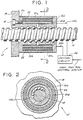
- FIG. 1 An improved ball nut 10, constructed in accordance with the teachings of the present invention, is illustrated in Figs. 1 and 2, Fig. 1 being a longitudinal cross section of the ball nut and Fig. 2 being a cross sectional view taken along lines 2-2 of Fig. 1.
- Ball nut 10 comprises a pair of nut halves 12a and 12b, each nut half being in threaded engagement with a ball screw 14 which is typically journaled for rotation in a fixed member, such as the bed of a machine tool (not shown).
- One of the ball nut halves, such as ball nut half 12a, for example, is secured by bolts 16 (only one of which is shown in Fig. 1) to a backet 18.
- bracket 18 is attached to a movable member (not shown), such as a machine tool axis slide.
- Nut halves 12a and 12b are separated by a pair of concentric sleeves 20a and 20b, each sleeve being keyed at its opposite ends to a separate one of the nut halves so as to prevent the nut halves from rotating independently of each other.
- Sleeves 20a and 20b are each fabricated from a piezomagnetic material, such as nickel or a nickel- steel alloy. The linkage of each nut half to the other by sleeves 20a and 20b causes both nut halves and hence, the machine tool axis slide, to be displaced along the ball screw as the ball screw is rotatably driven, typically by a servo motor (not shown) under command of the machine tool numerical control system (not shown).
- an electromagnetic coil 22 Disposed between sleeves 20a and 20b is an electromagnetic coil 22 whose windings lie perpendicular to the longitudinal axis of the ball screw.
- a direct current voltage is applied to coil leads 24a and 24b, from a control circuit 26, typically a voltage amplifier, in accordance with a control voltage supplied from the machine tool control system, the coil generates a magnetic field whose flux lines pass axially through each of the sleeves.
- a control circuit 26 typically a voltage amplifier
- the sleeves when subjected to the magnetic field produced by coil 22, tend to expand axially, urging ball nut halves 12a and 12b apart.
- each sleeve varies directly with the strength of the magnetic field, which varies in accordance with the current through the coil.
- Each sleeve when it expands axially in the presence of magnetic flux lines passing axially therethrough, exerts a force on the ball nut halves to urge them apart, the magnitude of the force varying in direct proportion to the axial expansion of the sleeve, which, as indicated, varies directly with the strength of the magnetic field.
- ball nut preloading can thus be varied in accordance with ball screw speeds so that at very high ball screw velocities, ball nut preloading can be reduced to obtain very high machine tool axis slide velocities.
- the ball nut preloading can be increased by increasing the magnetic coil excitation to increase ball nut loading to obtain very rigid coupling between the ball nut and the screw.
- Ball nut 10 achieves greater overall stiffness by virtue of the ball nut halves being separated by, but keyed to, sleeves 20a and 20b. The greater overall stiffness of ball nut 10 lessens the likelihood of chatter as the ball screw threadedly engages the ball nut during axial movement of the machine tool axis slide.
- the foregoing describes an improved ball nut having adjustable preloading so that at low ball screw speeds, ball nut preloading may be made high while at high ball screw speeds, the ball nut preloading can be reduced.
Landscapes
- Engineering & Computer Science (AREA)
- General Engineering & Computer Science (AREA)
- Mechanical Engineering (AREA)
- Transmission Devices (AREA)
Claims (2)
Applications Claiming Priority (2)
| Application Number | Priority Date | Filing Date | Title |
|---|---|---|---|
| US33198081A | 1981-12-18 | 1981-12-18 | |
| US331980 | 1981-12-18 |
Publications (2)
| Publication Number | Publication Date |
|---|---|
| EP0096072A1 EP0096072A1 (de) | 1983-12-21 |
| EP0096072B1 true EP0096072B1 (de) | 1988-01-20 |
Family
ID=23296181
Family Applications (1)
| Application Number | Title | Priority Date | Filing Date |
|---|---|---|---|
| EP83900378A Expired EP0096072B1 (de) | 1981-12-18 | 1982-12-13 | Kugelmutter mit einstellbarer vorspannung |
Country Status (6)
| Country | Link |
|---|---|
| EP (1) | EP0096072B1 (de) |
| CA (1) | CA1196516A (de) |
| DE (1) | DE3278022D1 (de) |
| IL (1) | IL67539A (de) |
| IT (1) | IT1157971B (de) |
| WO (1) | WO1983002142A1 (de) |
Cited By (2)
| Publication number | Priority date | Publication date | Assignee | Title |
|---|---|---|---|---|
| DE19734043A1 (de) * | 1997-08-06 | 1999-02-25 | Boris Dr Ing Vites | Kugelgewindetrieb |
| DE102007007885A1 (de) * | 2007-02-14 | 2008-09-04 | Fisw Steuerungstechnik Gmbh | Erzeugung einer konstanten Vorspannung für einen Kugelrollspindelgewindetrieb mit Doppelmutter |
Families Citing this family (6)
| Publication number | Priority date | Publication date | Assignee | Title |
|---|---|---|---|---|
| GB2223544B (en) * | 1988-03-14 | 1993-04-07 | Okuma Machinery Works Ltd | Feed-screw support structure |
| US4954032A (en) * | 1989-11-13 | 1990-09-04 | Windfred M. Berg, Inc. | Anti-backlash nut |
| DE69011113T2 (de) * | 1990-09-12 | 1995-03-02 | Kitamura Machinery Co Ltd | Eine Vorrichtung zum kontrollierten Vorspannen von Lagern. |
| US5704250A (en) * | 1996-04-04 | 1998-01-06 | Western Atlas, Inc. | Ball screw drive with dynamically adjustable preload |
| FR2790811B1 (fr) * | 1999-03-08 | 2001-04-13 | Transrol | Dispositif vis-ecrou a elements roulants interposes entre eux |
| CN211343905U (zh) | 2019-11-08 | 2020-08-25 | 全球传动科技股份有限公司 | 直线传动系统 |
Citations (5)
| Publication number | Priority date | Publication date | Assignee | Title |
|---|---|---|---|---|
| US3053106A (en) * | 1960-12-27 | 1962-09-11 | Tracer Control Company | Hydraulic nuts |
| US3638507A (en) * | 1970-02-26 | 1972-02-01 | Harry Orner | Preloaded ball-bearing screw and nut mechanism |
| DE2623014A1 (de) * | 1976-05-22 | 1977-11-24 | Ott Gerhard | Schneckengetriebe |
| SU748072A1 (ru) * | 1978-04-18 | 1980-07-15 | Московское Ордена Ленина И Ордена Трудового Красного Знамени Высшее Техническое Училище Им.Н.Э.Баумана | Шариковый винтовой механизм |
| SU752077A1 (ru) * | 1977-10-11 | 1980-07-30 | Витебский Станкостроительный Завод Им. С.М.Кирова | Шариковый винтовой механизм с предварительным нат гом |
Family Cites Families (6)
| Publication number | Priority date | Publication date | Assignee | Title |
|---|---|---|---|---|
| CH386809A (de) * | 1960-07-20 | 1965-01-15 | Oerlikon Buehrle Ag | Vorrichtung zur Spielregulierung an ausziehbarer Werkzeugmaschinenspindel |
| GB1005962A (en) * | 1962-04-05 | 1965-09-29 | Rotax Ltd | Screw and nut mechanisms |
| DE1935703A1 (de) * | 1968-07-30 | 1970-02-05 | Marwin Machine Tools Ltd | Einrichtung zur Einstellung der Reibung zwischen Maschinenteilen |
| DE1934840A1 (de) * | 1968-07-31 | 1970-02-05 | Marwin Machine Tools Ltd | Leitspindel |
| FR2082450A5 (de) * | 1970-03-17 | 1971-12-10 | Stephanois Rech | |
| FR2304001A1 (fr) * | 1975-03-12 | 1976-10-08 | Legueu Pierre | Vis a billes a precharge reglable |
-
1982
- 1982-12-13 WO PCT/US1982/001743 patent/WO1983002142A1/en not_active Ceased
- 1982-12-13 DE DE8383900378T patent/DE3278022D1/de not_active Expired
- 1982-12-13 EP EP83900378A patent/EP0096072B1/de not_active Expired
- 1982-12-17 CA CA000418056A patent/CA1196516A/en not_active Expired
- 1982-12-20 IT IT68492/82A patent/IT1157971B/it active
- 1982-12-22 IL IL67539A patent/IL67539A/xx unknown
Patent Citations (5)
| Publication number | Priority date | Publication date | Assignee | Title |
|---|---|---|---|---|
| US3053106A (en) * | 1960-12-27 | 1962-09-11 | Tracer Control Company | Hydraulic nuts |
| US3638507A (en) * | 1970-02-26 | 1972-02-01 | Harry Orner | Preloaded ball-bearing screw and nut mechanism |
| DE2623014A1 (de) * | 1976-05-22 | 1977-11-24 | Ott Gerhard | Schneckengetriebe |
| SU752077A1 (ru) * | 1977-10-11 | 1980-07-30 | Витебский Станкостроительный Завод Им. С.М.Кирова | Шариковый винтовой механизм с предварительным нат гом |
| SU748072A1 (ru) * | 1978-04-18 | 1980-07-15 | Московское Ордена Ленина И Ордена Трудового Красного Знамени Высшее Техническое Училище Им.Н.Э.Баумана | Шариковый винтовой механизм |
Cited By (2)
| Publication number | Priority date | Publication date | Assignee | Title |
|---|---|---|---|---|
| DE19734043A1 (de) * | 1997-08-06 | 1999-02-25 | Boris Dr Ing Vites | Kugelgewindetrieb |
| DE102007007885A1 (de) * | 2007-02-14 | 2008-09-04 | Fisw Steuerungstechnik Gmbh | Erzeugung einer konstanten Vorspannung für einen Kugelrollspindelgewindetrieb mit Doppelmutter |
Also Published As
| Publication number | Publication date |
|---|---|
| IT8268492A1 (it) | 1984-06-20 |
| CA1196516A (en) | 1985-11-12 |
| WO1983002142A1 (en) | 1983-06-23 |
| IL67539A0 (en) | 1983-05-15 |
| DE3278022D1 (en) | 1988-02-25 |
| EP0096072A1 (de) | 1983-12-21 |
| IL67539A (en) | 1987-09-16 |
| IT8268492A0 (it) | 1982-12-20 |
| IT1157971B (it) | 1987-02-18 |
Similar Documents
| Publication | Publication Date | Title |
|---|---|---|
| US4487087A (en) | Ball nut having adustable preloading | |
| EP3256286B1 (de) | Werkzeugmaschine und werkzeugmaschineneinheit | |
| US4956945A (en) | Internal grinder | |
| US4433590A (en) | Anti-backlash nut assembly | |
| US3273182A (en) | Feed control device to feed tool spindle at rate of tool advance | |
| US6208053B1 (en) | Adjustable torque hysteresis clutch | |
| US5169050A (en) | Wire bonder with improved actuator | |
| US5022294A (en) | Cutting apparatus for a noncircular cross section | |
| US4222692A (en) | Machine tool feed system with adjustable bearings | |
| WO1983002142A1 (en) | Ball nut having adjustable preloading | |
| US4640653A (en) | Integral spring flexure for use with high speed rotating shafts | |
| EP3528998A1 (de) | Motorspindel | |
| EP0231245B1 (de) | Werkzeugmaschinen | |
| GB2112679A (en) | Machine tools | |
| JPS6349083B2 (de) | ||
| JPS6150163B2 (de) | ||
| US9278421B2 (en) | Method for grinding workpieces, in particular for centering grinding of workpieces such as optical lenses | |
| JP3290087B2 (ja) | 静圧軸受を用いた位置決め装置 | |
| US3871246A (en) | Machine tools | |
| JPH0319031B2 (de) | ||
| JP2901692B2 (ja) | 複合旋盤の主軸制動装置 | |
| JPH05288255A (ja) | フェイルセイフ機構付き送りねじ装置および送りねじ装置のフェイルセイフシステム | |
| JPS6416349A (en) | Tool damage detecting device for spindle head | |
| JP2642797B2 (ja) | 穴加工方法およびその装置 | |
| US3681726A (en) | Electromagneto-mechanical actuator |
Legal Events
| Date | Code | Title | Description |
|---|---|---|---|
| PUAI | Public reference made under article 153(3) epc to a published international application that has entered the european phase |
Free format text: ORIGINAL CODE: 0009012 |
|
| AK | Designated contracting states |
Designated state(s): BE CH DE FR GB LI |
|
| 17P | Request for examination filed |
Effective date: 19831215 |
|
| GRAA | (expected) grant |
Free format text: ORIGINAL CODE: 0009210 |
|
| AK | Designated contracting states |
Kind code of ref document: B1 Designated state(s): BE CH DE FR GB LI |
|
| PG25 | Lapsed in a contracting state [announced via postgrant information from national office to epo] |
Ref country code: LI Effective date: 19880120 Ref country code: FR Free format text: THE PATENT HAS BEEN ANNULLED BY A DECISION OF A NATIONAL AUTHORITY Effective date: 19880120 Ref country code: CH Effective date: 19880120 Ref country code: BE Effective date: 19880120 |
|
| REF | Corresponds to: |
Ref document number: 3278022 Country of ref document: DE Date of ref document: 19880225 |
|
| REG | Reference to a national code |
Ref country code: CH Ref legal event code: PL |
|
| EN | Fr: translation not filed | ||
| PLBE | No opposition filed within time limit |
Free format text: ORIGINAL CODE: 0009261 |
|
| STAA | Information on the status of an ep patent application or granted ep patent |
Free format text: STATUS: NO OPPOSITION FILED WITHIN TIME LIMIT |
|
| PG25 | Lapsed in a contracting state [announced via postgrant information from national office to epo] |
Ref country code: GB Effective date: 19881213 |
|
| 26N | No opposition filed | ||
| GBPC | Gb: european patent ceased through non-payment of renewal fee | ||
| PG25 | Lapsed in a contracting state [announced via postgrant information from national office to epo] |
Ref country code: DE Effective date: 19890901 |