EP0096099A1 - Dispositif pour le transport de toiles de copeaux à compresser dans une presse à cuisson - Google Patents
Dispositif pour le transport de toiles de copeaux à compresser dans une presse à cuisson Download PDFInfo
- Publication number
- EP0096099A1 EP0096099A1 EP82105271A EP82105271A EP0096099A1 EP 0096099 A1 EP0096099 A1 EP 0096099A1 EP 82105271 A EP82105271 A EP 82105271A EP 82105271 A EP82105271 A EP 82105271A EP 0096099 A1 EP0096099 A1 EP 0096099A1
- Authority
- EP
- European Patent Office
- Prior art keywords
- loading
- press
- emptying
- tables
- heating
- Prior art date
- Legal status (The legal status is an assumption and is not a legal conclusion. Google has not performed a legal analysis and makes no representation as to the accuracy of the status listed.)
- Granted
Links
Images


Classifications
-
- B—PERFORMING OPERATIONS; TRANSPORTING
- B27—WORKING OR PRESERVING WOOD OR SIMILAR MATERIAL; NAILING OR STAPLING MACHINES IN GENERAL
- B27N—MANUFACTURE BY DRY PROCESSES OF ARTICLES, WITH OR WITHOUT ORGANIC BINDING AGENTS, MADE FROM PARTICLES OR FIBRES CONSISTING OF WOOD OR OTHER LIGNOCELLULOSIC OR LIKE ORGANIC MATERIAL
- B27N3/00—Manufacture of substantially flat articles, e.g. boards, from particles or fibres
- B27N3/08—Moulding or pressing
- B27N3/20—Moulding or pressing characterised by using platen-presses
- B27N3/22—Charging or discharging
Definitions
- the invention relates to a device for pressing chip fleeces dissolved in individual moldings on documents by means of feeders, press feeding device, multi-day heating press, press emptying device and a separating device for separating the finished chipboard from the base, and a method for loading a multi-day heating press with chip fleece to be pressed.
- a press loading device which is designed as a loading basket.
- a multi-day heating press is loaded from the loading basket, after the pressing process has been carried out, the finished chipboard is removed from the heating press, into a press emptying device, which is designed as a press emptying basket, and passed on from this emptying basket via a separating device in such a way that the chipboard for themselves and in another production line, the documents freed from the chipboard are transported.
- Such press loading and emptying baskets are very complex, since a conveying device must be arranged in each press loading basket in order to transport the not yet pressed chipboard and the pressed chipboard.
- the object of the present invention is to reduce the effort involved in loading and emptying a heating press, to increase its safety and also to accelerate the press cycle: with the press cycle the period of loading, pressing, and emptying a heating press with chip fleeces and the separation of the finished chipboard from the documents is understood.
- This object is achieved with the features of claim 1) according to the invention. Due to the articulated connection of loading and emptying tables with each heating plate according to the invention, the previously complex adjustment between loading device and heating press plate is eliminated and destruction of chip fleece to be pressed is clearly avoided, since no adjustment errors can occur.
- the cycle of loading and emptying is forcibly synchronized by using the conveyor according to the invention, so that a collision between documents that have not yet pressed chip fleeces and documents that already carry a pressed chipboard are clearly excluded.
- a further embodiment of the subject matter of the invention is protected under the characterizing part of claim 3).
- a further increase in the number of floors of a multi-day heating press can be achieved, or a kinking of the loading table can be avoided.
- the inventive feature of claim 6 serves the present application.
- the conditions of the side of the chip fleece lying on the base are adapted to the conditions as are given for the other side of the chip fleece when the chip fleece is moved into the open heating press.
- Water, air or 01 can serve as the heating medium.
- the characterizing features of claim 7) disclose a particularly expedient vehicle for the transport of hot air for heating as well as the characterizing features of claim 8) use the press itself as a heat source.
- the inventive designs according to the characterizing features of claims 9) and 10) take into account the requirement that chipboard nonwovens to be pressed in during a standstill in production are not unnecessarily heated from one side and that the glue already begins to harden before the pressing process.
- the characterizing features of claim 11) ensure that even during the pressing process, i.e. when the press is closed, constant movement and thus cooling of the conveyor is made possible, so that V-belts can also be used as conveyor elements instead of chain conveyors.
- the design of the subject matter of the invention to be protected according to the characterizing features of claim 12) shows a way in which a lifting or lowering of loading and unloading tables can be carried out in the simplest manner while maintaining a constant distance between the individual tables, without an additional positive guidance, since the spacers on the respective lower table can slide along each other according to the inclination of the tables.
- equivalent means such as compressed air or hydraulic systems, can occur; eccentric drives are also suitable as equivalents to the subject of the invention.
- a three-day pressing system is shown schematically, in which a feed conveyor 1, which is shown schematically as a conveyor belt, in its current position with the help of an auxiliary conveyor 2 can load a lowermost loading table 3 with a chip fleece 6 to be pressed located on a base 5.
- the auxiliary conveyor 2 which is located on the left and right of the feed conveyor and above it, is extended into its right end position. It engages with a thrust member 7 and 7 header 4 of the base 5 left and right of the feed conveyor 1 and brings it into the area of a drag conveyor 9 wrapped around a first deflection wheel 8, which is provided with drivers that engage behind the header 4 and thus on Pull the chip fleece 6 on the base 5 onto the lowest loading table 3.
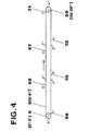
- the operation of the drag conveyor 9, which can consist of a chain conveyor or a V-belt conveyor, is described in more detail in connection with FIG. 4.
- the lowermost loading table 3 is moved via a tension element 10 via a deflection roller 11, for the right side in the conveying direction and via a deflection roller 11 ', for the left side in the conveying direction of the lowest loading tables 3 led.
- the deflection rollers 11, 11 ' are driven by a motor 12 which can be switched in its direction of rotation.
- a middle loading table 13 and an upper loading table 14 are supported by spacers 15 or 15 'and 16 or 16' arranged on the left and right of the loading tables 13 and 14 with their free ends and are connected at their other ends via joints 17, 18, 19, which extend over the entire width of the loading tables, are connected to press plates 20, 21, 22 of a three-day heating press 23.
- the motor 12 is driven in such a direction of rotation that the middle loading table in front of the auxiliary conveyor 2 is aligned with the feed conveyor 1.
- a further base 5 with a further chip fleece 6 is brought into the area of influence of a second deflection wheel 8 'by means of pusher element 7 and is pulled onto the middle loading table by drivers of a second drag conveyor 9'.
- the traction element 10 or 10 ' is moved downwards by means of motor 12 and deflection rollers 11, 11' until the upper loading table 14 is lowered into a take-over position, so that also on this loading table 14 by means of a third deflecting wheel 8 "and a third drag conveyor 9 "a pad 5 covered with a chip fleece can be pulled up.
- a lower emptying table 24 is a middle emptier table 25 and an upper discharge table 26 are provided, which are also articulated with joints 17 ', 18', 19 'with the press plates 20, 21 and 22 at the heating plate outlet of the heating press 23.
- the free ends of the emptying tables 24, 25, 26, as already described for the loading tables 3, 13 and 14, can be raised and lowered via pulling elements 10, 10 ', deflection rollers 11, 11' and a motor 12 which can be switched in the direction of rotation. so that after the individual chipboard has been removed from the corresponding emptying table, the emptying tables arranged one above the other can be raised or lowered so that the next emptying table can be freed from the chipboard 27 still on the documents 5.
- the drag conveyors 9, 9 ', 9 are driven by a reversible motor 29 via drive wheels 28, 28', 28".
- a reversible motor 29 can be provided for each drag conveyor or, with the aid of a link control in the simplest configuration, each drag conveyor can be driven by the one motor alone.
- a take-over conveyor 30 engages behind the head strip 4 of the base 5 with its pull-out hook 31 and brings it, including the chipboard 27, into the area of influence of a separating roller 32, which has drivers 33, by moving to the right into the dashed position.
- the take-over conveyor 30 moves so far to the right that the headers 4 can be hung in the driver 33.
- the base 5 which in this case is designed as a flexible base, is pulled downwards, while the finished chipboard itself is fed to a further processing via a roller table 34.
- the separating roller 32 By the rotation of the separating roller 32, the base 5 is fed to a return conveyor 35, which brings this base back into the returning run of the feed conveyor 1, from where the base is again supplied with a new chip fleece to be pressed.
- the separating roller 32 is replaced in the simplest form, for example, by an intermediate conveyor 354 (see FIG. 1a) which can also be towed with the help of drivers 33, support plates 36 including the chipboard 27 with the aid of the take-over conveyor 30 and the pull-out hook 31.
- the intermediate conveyor 35a runs in the direction of the arrow until the support plate 36, including chipboard 27, is slipped onto the upper side of the intermediate conveyor 35a ().
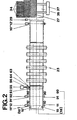
- the intermediate conveyor 35a is then braked and it acts through a cross-directional direction of progress 2, the chipboard, as shown in Fig. 2, is pushed onto the roller table 34 which runs parallel to the conveying direction of the emptying tables.
- the intermediate conveyor 35 is pivoted about its drive shaft 38 so that A motor 39 which drives the intermediate conveyor 35 now starts reversing and places the respective support plate 36 on the return conveyor 35 shown in broken lines. From here the support plate is again subjected to a new load of chip fleece brought the feed conveyor 1 back.
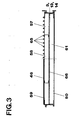
- a heating press with a larger number of floors can now also occur, if the requirement is met that, for example in a five-day press, the angle of inclination between a further feed table 40 and a further press plate 41 is not exceeded when the chip fleece is drawn into the heating press. It is also necessary to take into account the requirement that the transfer angle between the feed conveyor 1 and the loading tables does not exceed a maximum bending angle if flexible documents are used as documents, since otherwise there is a risk of a structural change in the chip fleece.
- the loading tables in the exemplary embodiment the loading table 40, with at least one bend 42, as a result of which the supporting surface of the further loading table 40 is given a supporting surface as shown in dashed lines in FIG. 1 ; or to design the feed conveyor 1 in the region of its deflection roller 43 such that it can move in height as shown by a double arrow 44, or to align the transfer level of the feed conveyor 1 to the middle level of the baling press level, in the exemplary embodiment according to FIG Takes position.
- both the lifting and lowering device consisting of tension element 10, 10 ', deflection roller 11, 11' and motor 12 which can be switched in its direction of rotation can be pivoted about this level, for loading the individual loading tables, and the feed conveyor can also be used 1 can be pivoted about this level by lifting or lowering in accordance with the double arrow 44, so that the permissible size of the articulation angle is not exceeded even when transferring feeders to the loading table.
- the permissible articulation angle between the forming belt (not shown) and the feed conveyor 1 now exceeds the approved articulation angle, it is proposed according to the invention to provide the feed conveyor with a kink accordingly, so that even with a high number of floors allowed kink angle from the transition from one to the other conveyor must not be exceeded, since several kinks can also be arranged in the support sides of the loading tables or the feed conveyor, which causes the feed conveyor or the loading table to be inclined clockwise or counterclockwise.
- a further lifting and lowering device consisting of tension elements 90, 90 ', deflection rollers 91, 91' and a drive motor 92 is arranged in the area of the feed tables 3, 13, 14 and the feed tables each have additional joints 93, 94, 95 and supports 96, 97 so a variable kink angle can be generated according to the requirements. If the drive motors 12 and 92 are controlled accordingly, articulation angles can be generated both clockwise and counterclockwise.
- the carrying side of the feed conveyor 1 can also be designed, so that here, too, minimal wear and also a minimal structural change in the one not yet compressed during the transfer from the forming belt to the feed conveyor and from the feed conveyor to the loading tables Chip fleece even when using a multi-floor heating press with a high number of floors is achieved.
- the thickness of the unpunched chip fleece is measured by arranging a layer thickness meter 48 on the feed conveyor 1. This information is sent to senders 52, 53 and 54 located on the press. As a result of this information, the press nip of each floor is set accordingly, so that even minimal free travel must be overcome during the pressing process. It is therefore possible according to the invention, by monitoring the thickness of the chip nonwovens to be pressed on each feed table, to press chip nonwovens of different thicknesses without having to open all floors to their maximum clear width.
- FIG. 2 shows the course of the heating channels in the area of the feed tables 3, 13 and 14, which in the exemplary embodiment are acted upon by an external heat source 55 via a fan 56.
- the heat medium is transported along three channels 57, 58, 59 against the conveying direction in the upper half of each loading table 3, 13, 14, at the free end of the loading tables 3, 13, 14 in discharge a region 60 into a closed return flow chamber 61 and either return it via the outlet pipe 62 and heat it up in a circuit via a pressure line 63, return it through the external heat source 55 or, in the event of a standstill during the production of chipboard, lead it out into the open via a discharge pipe 64.
- the hot press plates of the three-day heating press 23 can serve as a heat source.
- the single press plate consists of two heating plates through which the heating medium flows, which are connected to a spacer construction made of vertically standing steel sheets.
- cooling air is sucked in via the fan 56, which initially flows through the individual press plates 20, 21, 22, which are heated by a heating medium, water, oil, so that they become uniform the temperature via the press plate, which keeps the temperature constant even with frequent batch changes within the heating press.
- the warmed-up air is then passed through the channels 57, 58, 59 within the loading tables and thus the preforms stored on the loading tables are preheated.
- the cooling air flows through the return flow chamber 61 either cooled in the circuit again through the press plates 20, 21, 22 or partly exchanged with new cooling air, likewise mixing this way for heating up molded articles to be pressed.
- the air present within the loading tables is immediately discharged into the open via the outlet connection 64, so that unnecessary heating of the moldings, which could lead to premature curing, is avoided.
- a sheet metal cover which can be made of aluminum, for example, is provided as the supporting side 46 of a loading table, and a grate cover 65 is shown on the other side, on which the screen fabric 5 or sheet metal 36 directly rests.
- a partition 66 which can consist, for example, of a particle board, the channels 57, 58, 59 are separated from the return flow chamber 61, so that mixing between the cooled heating medium and the hot heating medium is clearly avoided.
- the backflow chamber is provided with a further cover 50.
- one embodiment of the invention provides that the further cover 50 is omitted and the molded part to be pressed can thus reach up to the partition 66.
- the channels 57, 59 are used as flow channels for heating the fleece to be pressed channels used opposite to the conveying direction and the channel 58 as a return flow channel.
- drag conveyors 9, 9 ', 9 " the feed tables, floors and emptying tables belonging to them are wrapped. Furthermore, the drag conveyors can be driven together and individually, so that during the pressing process the individual feed tables 3, 13, 14 can be fed one after the other without any effects on the chipboard being pressed or the documents under it.
- a total of six drag bar drivers 67, 68, 69, 70, 71 and 72 are provided on the circumference of the drag conveyor 9. During the loading process, all are The drag chain driver moves from position b 'in the conveying direction according to the arrow to the right until it has reached the position a' of the drag chain driver 67.
- the drag chain driver 67 moves from its position a 'by taking the chipboard support contained in the press into a position f' of the drag chain follower 71, the drag chain follower 71 moves from the position f 'in di e position e ', if a base 5 provided with a chipboard was still contained on the emptying table, this is brought with its drag bar 4 with the aid of the drag chain driver 71 into the area of the pull-out hook 31 and introduced into the separation by the take-over conveyor 30.
- the feed conveyor 1 is simultaneously towed from the position c 'to the position b' in the corresponding position according to FIG.
- the drag conveyor 9 'wrapped around the middle loading table and emptying table is pulled back against the conveying direction, the loading table 13 is lowered into the transfer plane and then moved again from position c' into position b by moving the carrier corresponding to the drag bar driver 69 again '' loaded the next floor with a molding to be pressed.
- the loading of the upper loading table 14 is carried out in the same way.
Landscapes
- Life Sciences & Earth Sciences (AREA)
- Engineering & Computer Science (AREA)
- Manufacturing & Machinery (AREA)
- Wood Science & Technology (AREA)
- Forests & Forestry (AREA)
- Dry Formation Of Fiberboard And The Like (AREA)
- Press Drives And Press Lines (AREA)
- Stringed Musical Instruments (AREA)
- Medicines Containing Plant Substances (AREA)
- Casting Or Compression Moulding Of Plastics Or The Like (AREA)
- Treatment Of Fiber Materials (AREA)
- Nonwoven Fabrics (AREA)
Priority Applications (5)
| Application Number | Priority Date | Filing Date | Title |
|---|---|---|---|
| AT82105271T ATE21061T1 (de) | 1982-06-16 | 1982-06-16 | Einrichtung zum transport von zu verpressenden spaenevliesen im bereich einer heizpresse. |
| EP82105271A EP0096099B1 (fr) | 1982-06-16 | 1982-06-16 | Dispositif pour le transport de toiles de copeaux à compresser dans une presse à cuisson |
| DE8282105271T DE3272298D1 (en) | 1982-06-16 | 1982-06-16 | Transporting device for webs of chips to be pressed in a heating press |
| CA000425588A CA1208112A (fr) | 1982-06-16 | 1983-04-11 | Dispositif d'alimentation et de reprise d'une presse |
| FI832111A FI72283C (fi) | 1982-06-16 | 1983-06-13 | Anordning vid en varmpress foer transport av foer pressning avsedda spaonmattor och foerfarande foer beskickning av en varmpress. |
Applications Claiming Priority (1)
| Application Number | Priority Date | Filing Date | Title |
|---|---|---|---|
| EP82105271A EP0096099B1 (fr) | 1982-06-16 | 1982-06-16 | Dispositif pour le transport de toiles de copeaux à compresser dans une presse à cuisson |
Publications (2)
| Publication Number | Publication Date |
|---|---|
| EP0096099A1 true EP0096099A1 (fr) | 1983-12-21 |
| EP0096099B1 EP0096099B1 (fr) | 1986-07-30 |
Family
ID=8189089
Family Applications (1)
| Application Number | Title | Priority Date | Filing Date |
|---|---|---|---|
| EP82105271A Expired EP0096099B1 (fr) | 1982-06-16 | 1982-06-16 | Dispositif pour le transport de toiles de copeaux à compresser dans une presse à cuisson |
Country Status (5)
| Country | Link |
|---|---|
| EP (1) | EP0096099B1 (fr) |
| AT (1) | ATE21061T1 (fr) |
| CA (1) | CA1208112A (fr) |
| DE (1) | DE3272298D1 (fr) |
| FI (1) | FI72283C (fr) |
Cited By (2)
| Publication number | Priority date | Publication date | Assignee | Title |
|---|---|---|---|---|
| CN111422541A (zh) * | 2020-03-30 | 2020-07-17 | 山东森工机械制造有限公司 | 可移动式装卸板机及装卸方法 |
| CN111593483A (zh) * | 2020-05-27 | 2020-08-28 | 埃日尔环保科技(苏州)有限公司 | 一种无纺布生产用热压机 |
Citations (1)
| Publication number | Priority date | Publication date | Assignee | Title |
|---|---|---|---|---|
| DE2236355B2 (de) * | 1972-07-25 | 1977-10-20 | G. Siempelkamp Gmbh & Co, 4150 Krefeld | Anlage zum beschicken von mehretagenplattenpressen |
-
1982
- 1982-06-16 EP EP82105271A patent/EP0096099B1/fr not_active Expired
- 1982-06-16 AT AT82105271T patent/ATE21061T1/de not_active IP Right Cessation
- 1982-06-16 DE DE8282105271T patent/DE3272298D1/de not_active Expired
-
1983
- 1983-04-11 CA CA000425588A patent/CA1208112A/fr not_active Expired
- 1983-06-13 FI FI832111A patent/FI72283C/fi not_active IP Right Cessation
Patent Citations (1)
| Publication number | Priority date | Publication date | Assignee | Title |
|---|---|---|---|---|
| DE2236355B2 (de) * | 1972-07-25 | 1977-10-20 | G. Siempelkamp Gmbh & Co, 4150 Krefeld | Anlage zum beschicken von mehretagenplattenpressen |
Cited By (3)
| Publication number | Priority date | Publication date | Assignee | Title |
|---|---|---|---|---|
| CN111422541A (zh) * | 2020-03-30 | 2020-07-17 | 山东森工机械制造有限公司 | 可移动式装卸板机及装卸方法 |
| CN111422541B (zh) * | 2020-03-30 | 2024-02-20 | 山东森工机械制造有限公司 | 可移动式装卸板机及装卸方法 |
| CN111593483A (zh) * | 2020-05-27 | 2020-08-28 | 埃日尔环保科技(苏州)有限公司 | 一种无纺布生产用热压机 |
Also Published As
| Publication number | Publication date |
|---|---|
| FI832111A0 (fi) | 1983-06-13 |
| FI72283B (fi) | 1987-01-30 |
| CA1208112A (fr) | 1986-07-22 |
| EP0096099B1 (fr) | 1986-07-30 |
| FI72283C (fi) | 1987-05-11 |
| FI832111L (fi) | 1983-12-17 |
| DE3272298D1 (en) | 1986-09-04 |
| ATE21061T1 (de) | 1986-08-15 |
Similar Documents
| Publication | Publication Date | Title |
|---|---|---|
| DE112008001971T5 (de) | Kontinuierlich arbeitende Pressmaschine | |
| DE2612206A1 (de) | Heb- und senkbare formlingsbeschickungs- und pressunterlagen-entleerungsvorrichtung fuer eine mehretagenpresse | |
| DE2547149B2 (de) | Stapelvorrichtung zur Beschickung einer Etagenpresse | |
| EP3363607B1 (fr) | Dispositif et procédé d'évacuation de copeaux de bois réalisés latéralement à partir d'une presse continue | |
| DE69729683T2 (de) | Vorrichtung zur Heizung von Furnier | |
| EP0344192B1 (fr) | Procede et installation de fabrication de panneaux en copeaux de bois et materiaux similaires | |
| EP0458806B1 (fr) | Procede et installation de production de panneaux d'agglomeres en bois et de materiaux similaires pour panneaux | |
| DE69020720T2 (de) | Vorrichtung zur Plattenbearbeitung unter Verwendung einer Raupenkette. | |
| EP0096099B1 (fr) | Dispositif pour le transport de toiles de copeaux à compresser dans une presse à cuisson | |
| DE3409178C2 (de) | Einrichtung zum Zusammensetzen und Verbinden von flächigen Werkstücken | |
| EP0112470B1 (fr) | Installation pour moules de fonderie | |
| WO2002076697A1 (fr) | Procede de production continue de panneaux de particules et de materiaux sous forme de panneaux similaires et presse a double bande adaptee | |
| DE4208263A1 (de) | Kontinuierliche presse fuer das pressen einer pressgutmatte im zuge der herstellung von spanplatten, faserplatten u. dgl. | |
| EP4118018B1 (fr) | Système de chargement | |
| DE2820788C2 (de) | Plattenpreßfilter mit mehrfach angetriebenem endlosem Filterband | |
| DE2226897C3 (de) | Formungs- und Pressenstraße für die Herstellung von Spanplatten | |
| DE102016117543B4 (de) | Überführungseinrichtung einer oder für eine Fördervorrichtung, Fördervorrichtung, Produktionsanlage und Verfahren zum Betreiben einer Produktionsanlage | |
| DE3914107C2 (de) | Kontinuierliche Presse zum Pressen und Wärmebehandeln von Preßgutmatten | |
| DE19810304C1 (de) | Verfahren und Doppelbandpresse zur kontinuierlichen Herstellung von Plattenwerkstoffen | |
| DE2010686C3 (de) | Beschickvorrichtung für Oberflächenbeschichtungspressen | |
| EP1062087B1 (fr) | Procede et presse a deux rubans pour la production en continu de materiaux en plaques | |
| DE3031683A1 (de) | Kurztaktpresse zum beschichten flaechiger werkstuecke | |
| DE10150041A1 (de) | Austrag-Kühleinrichtung für eine Druckmaschine | |
| DE19856866C2 (de) | Doppelbandpresse zur kontinuierlichen Herstellung von Plattenwerkstoffen | |
| CH661243A5 (de) | Anlage zum pressen von faserzementplatten. |
Legal Events
| Date | Code | Title | Description |
|---|---|---|---|
| PUAI | Public reference made under article 153(3) epc to a published international application that has entered the european phase |
Free format text: ORIGINAL CODE: 0009012 |
|
| 17P | Request for examination filed |
Effective date: 19830329 |
|
| AK | Designated contracting states |
Designated state(s): AT BE CH DE FR GB IT LI LU NL SE |
|
| ITF | It: translation for a ep patent filed | ||
| GRAA | (expected) grant |
Free format text: ORIGINAL CODE: 0009210 |
|
| AK | Designated contracting states |
Kind code of ref document: B1 Designated state(s): AT BE CH DE FR GB IT LI LU NL SE |
|
| REF | Corresponds to: |
Ref document number: 21061 Country of ref document: AT Date of ref document: 19860815 Kind code of ref document: T |
|
| REF | Corresponds to: |
Ref document number: 3272298 Country of ref document: DE Date of ref document: 19860904 |
|
| ET | Fr: translation filed | ||
| PLBE | No opposition filed within time limit |
Free format text: ORIGINAL CODE: 0009261 |
|
| STAA | Information on the status of an ep patent application or granted ep patent |
Free format text: STATUS: NO OPPOSITION FILED WITHIN TIME LIMIT |
|
| PG25 | Lapsed in a contracting state [announced via postgrant information from national office to epo] |
Ref country code: LU Free format text: LAPSE BECAUSE OF NON-PAYMENT OF DUE FEES Effective date: 19870630 |
|
| PGFP | Annual fee paid to national office [announced via postgrant information from national office to epo] |
Ref country code: NL Payment date: 19870630 Year of fee payment: 6 |
|
| 26N | No opposition filed | ||
| PGFP | Annual fee paid to national office [announced via postgrant information from national office to epo] |
Ref country code: SE Payment date: 19890512 Year of fee payment: 8 |
|
| PGFP | Annual fee paid to national office [announced via postgrant information from national office to epo] |
Ref country code: CH Payment date: 19890522 Year of fee payment: 8 |
|
| PGFP | Annual fee paid to national office [announced via postgrant information from national office to epo] |
Ref country code: BE Payment date: 19890525 Year of fee payment: 8 |
|
| PGFP | Annual fee paid to national office [announced via postgrant information from national office to epo] |
Ref country code: DE Payment date: 19890607 Year of fee payment: 8 |
|
| PG25 | Lapsed in a contracting state [announced via postgrant information from national office to epo] |
Ref country code: GB Effective date: 19890616 Ref country code: AT Effective date: 19890616 |
|
| ITTA | It: last paid annual fee | ||
| PG25 | Lapsed in a contracting state [announced via postgrant information from national office to epo] |
Ref country code: NL Effective date: 19900101 |
|
| GBPC | Gb: european patent ceased through non-payment of renewal fee | ||
| NLV4 | Nl: lapsed or anulled due to non-payment of the annual fee | ||
| PG25 | Lapsed in a contracting state [announced via postgrant information from national office to epo] |
Ref country code: FR Free format text: LAPSE BECAUSE OF NON-PAYMENT OF DUE FEES Effective date: 19900228 |
|
| REG | Reference to a national code |
Ref country code: FR Ref legal event code: ST |
|
| PG25 | Lapsed in a contracting state [announced via postgrant information from national office to epo] |
Ref country code: SE Effective date: 19900617 |
|
| PG25 | Lapsed in a contracting state [announced via postgrant information from national office to epo] |
Ref country code: LI Effective date: 19900630 Ref country code: CH Effective date: 19900630 Ref country code: BE Effective date: 19900630 |
|
| BERE | Be: lapsed |
Owner name: CARL SCHENCK A.G. Effective date: 19900630 |
|
| REG | Reference to a national code |
Ref country code: CH Ref legal event code: PL |
|
| PG25 | Lapsed in a contracting state [announced via postgrant information from national office to epo] |
Ref country code: DE Effective date: 19910301 |
|
| EUG | Se: european patent has lapsed |
Ref document number: 82105271.9 Effective date: 19910206 |