EP0096175A1 - Schweissstellenfreie Verbindung - Google Patents
Schweissstellenfreie Verbindung Download PDFInfo
- Publication number
- EP0096175A1 EP0096175A1 EP83102658A EP83102658A EP0096175A1 EP 0096175 A1 EP0096175 A1 EP 0096175A1 EP 83102658 A EP83102658 A EP 83102658A EP 83102658 A EP83102658 A EP 83102658A EP 0096175 A1 EP0096175 A1 EP 0096175A1
- Authority
- EP
- European Patent Office
- Prior art keywords
- tube
- bushing
- screwed
- section
- abutting
- Prior art date
- Legal status (The legal status is an assumption and is not a legal conclusion. Google has not performed a legal analysis and makes no representation as to the accuracy of the status listed.)
- Granted
Links
- 238000003466 welding Methods 0.000 claims description 2
- 238000007789 sealing Methods 0.000 abstract description 7
- 239000007788 liquid Substances 0.000 description 13
- 238000005253 cladding Methods 0.000 description 1
- 230000008602 contraction Effects 0.000 description 1
- 238000005516 engineering process Methods 0.000 description 1
- 230000017525 heat dissipation Effects 0.000 description 1
- 238000010438 heat treatment Methods 0.000 description 1
- 238000000034 method Methods 0.000 description 1
- 230000005855 radiation Effects 0.000 description 1
- 238000000926 separation method Methods 0.000 description 1
Images



Classifications
-
- F—MECHANICAL ENGINEERING; LIGHTING; HEATING; WEAPONS; BLASTING
- F16—ENGINEERING ELEMENTS AND UNITS; GENERAL MEASURES FOR PRODUCING AND MAINTAINING EFFECTIVE FUNCTIONING OF MACHINES OR INSTALLATIONS; THERMAL INSULATION IN GENERAL
- F16L—PIPES; JOINTS OR FITTINGS FOR PIPES; SUPPORTS FOR PIPES, CABLES OR PROTECTIVE TUBING; MEANS FOR THERMAL INSULATION IN GENERAL
- F16L41/00—Branching pipes; Joining pipes to walls
-
- F—MECHANICAL ENGINEERING; LIGHTING; HEATING; WEAPONS; BLASTING
- F24—HEATING; RANGES; VENTILATING
- F24S—SOLAR HEAT COLLECTORS; SOLAR HEAT SYSTEMS
- F24S20/00—Solar heat collectors specially adapted for particular uses or environments
- F24S20/60—Solar heat collectors integrated in fixed constructions, e.g. in buildings
- F24S20/66—Solar heat collectors integrated in fixed constructions, e.g. in buildings in the form of facade constructions, e.g. wall constructions
-
- Y—GENERAL TAGGING OF NEW TECHNOLOGICAL DEVELOPMENTS; GENERAL TAGGING OF CROSS-SECTIONAL TECHNOLOGIES SPANNING OVER SEVERAL SECTIONS OF THE IPC; TECHNICAL SUBJECTS COVERED BY FORMER USPC CROSS-REFERENCE ART COLLECTIONS [XRACs] AND DIGESTS
- Y02—TECHNOLOGIES OR APPLICATIONS FOR MITIGATION OR ADAPTATION AGAINST CLIMATE CHANGE
- Y02B—CLIMATE CHANGE MITIGATION TECHNOLOGIES RELATED TO BUILDINGS, e.g. HOUSING, HOUSE APPLIANCES OR RELATED END-USER APPLICATIONS
- Y02B10/00—Integration of renewable energy sources in buildings
- Y02B10/20—Solar thermal
Definitions
- the invention relates to a device for the weld-free connection of substantially perpendicular pipes of the piping system of a temperature control device.
- Such a piping system is arranged, for example, on the outer walls of a building in the area of the facade cladding.
- the sections of the pipeline system which form the posts and transoms are heated by solar radiation, after which this can be used for heating rooms.
- the piping system forms a forward and a return system for a means of heat supply and a forward and a return system for a means of heat dissipation.
- the creation of such a piping system is problematic since the connection points have to meet certain conditions in terms of flow technology. From DE-PS 28 57 662 a device is known with which vertically abutting pipes in the form of T-connections can be connected without welding points. In this case, a bushing is screwed into the end of a pipe, in which an axial, central internal thread is formed, by means of which the pipe running perpendicular to it can be clamped.
- the invention has for its object to provide a device with which crossing tubes can be connected to each other without welds.
- the solution to this problem is according to the invention characterized in that two pipes are aligned with each other on a continuous pipe, that a through hole is formed in the continuous pipe, that in the end of each of the abutting pipes a partially protruding bushing is arranged and that the sockets are connected to each other.
- the area of the bushings protruding from the pipe ends is inserted into the inside of the through hole in the through pipe.
- the two sockets in the tubes are connected to one another by suitable means, this connection being able to be made from a tube using a suitably long tool.
- an externally threaded bushing with an axial central threaded bore that in the end of the other butting pipe an externally threaded bushing with an axially central through-hole is screwed in and that the connection of the Bushings are made using a screw bolt.
- a threaded section is provided in one bushing, into which the screw bolt can be screwed, while a through hole is arranged in the other bushing, which serves as an abutment for the screw bolt.
- the screw bolt can be designed with a hexagon socket on its head (Allen screw) 7 so that it can be screwed into the sockets with an appropriately long Allen key.
- a sleeve connecting the bushes is arranged coaxially with the screw bolt.
- the protruding ends of the bushings can be conical and the ends of the sleeve can be pressed into the bushings.
- Such a connection of the two sockets creates a separation of the perpendicular currents in the piping system. If the sleeve is omitted, the liquid flows are mixed at the crossing point.
- the heat transport liquid can pass through the bushings, they can be designed either with axially directed bores or with approximately semi-annular through openings.
- the bushing has two end sections which are connected to one another via a central tube section and are provided with an external thread.
- the middle pipe section extends in the area of the continuous pipe, while the two end sections protrude from the pipe on both sides so that the ends of the abutting pipes can be screwed on.
- one end section is designed with a left-hand thread and the other end section with a right-hand thread.
- they can be designed with an internal hexagon at the ends, so that an appropriately long Allen key can be used.
- the outer diameter of the central tube section is smaller than the inner diameter of the continuous tube. If a mixing of the intersecting liquid flows is desired, it can be provided that the wall of the central tube section of the bushing is formed with through holes.
- the bushing is provided on one of the end sections connected via a central pipe section with an external thread which can be screwed into the abutting pipe, and that one in the other pipe with externally threaded auxiliary bush is screwed in, which is arranged in a tight fit on part of the other end section of the bush, that this end section of the bush is partially provided with an external thread, and that an annular nut with an internal thread is screwed thereon.
- This division of the one end section of the bushing prevents the sealing ring provided between the abutting tube and the continuous tube from being damaged when screwing in.
- the ring-shaped nut it can be designed with an internal hexagon at its end.
- the outer diameter of the central tube section of the bushing is preferably smaller than the inner diameter of the continuous tube.
- the ends of the abutting tubes can preferably be provided with annular recesses into which the O-ring can be inserted.
- a through bore 16 is formed in the continuous tube 10.
- the end of the abutting tube 12 is provided with an internal thread 18, the end of the abutting tube 14 with an internal thread 20.
- the ends of the tubes 12 and 14 are with annular recesses 26, 28 Mistake.
- a bushing 30, which is provided with an external thread, is screwed into the end of the tube 12.
- the socket 30 projects from the tube 12 with a section 32.
- the section 32 has a length which corresponds approximately to the wall thickness of the continuous tube 10.
- the bushing 30 is provided with through openings 34 which can either be coaxial bores or approximately semicircular rings.
- a bore 36 with an internal thread is arranged axially and centrally in the bushing and is used for screwing in a screw bolt 38.
- a bushing 40 is screwed into the end of the pipe 14 provided with the internal thread 20 and protrudes with a section 42 from the pipe 14.
- the socket 42 is provided with through holes 44 leading to the through serving the liquid. These through holes can also be designed as approximately semi-annular passages.
- a through bore 46 is formed axially and centrally in the bush 40, through which the screw bolt 38 can extend.
- the end of the socket serves as an abutment for the head 48 of the screw bolt 38, which is provided, for example, with an internal hexagon the resulting annular grooves between the pipe ends and the bushings and the end portions 32 and 42 are inserted into the through hole 16 in the continuous tube 10.
- the screw bolt 38 is inserted through the tube 14 with a correspondingly long tool, inserted through the bushing 40 and screwed into the bore 36 in the bushing 30.
- a sleeve 50 can be fitted between the ends 32 and 42 of the bushings 30 and 40, respectively.
- the outer diameter of the sleeve 50 is less than the inner diameter of the tube 10, so that the liquid can flow around the sleeve.
- the end portions of the bushings can be conical on the inside, so that the sleeve 50 is pressed into the bushing ends during the contraction of the bushings 30 and 40.
- Fig. 2 shows a section through the socket 30, from which the configuration of the through openings through the socket can be seen.
- FIG. 3 shows an intersection in a pipeline system in which a continuous pipe 60 is connected to two butting pipes 62 and 64, respectively.
- a through bore 66 is formed in the tube 60, the tubes 62 and 64 are connected via a bushing 67 formed in one piece / with two end portions 68 and 70 which are connected to one another via a central tube portion 72.
- the ends of the tubes 62 and 64 are in turn provided with recesses into which sealing rings 74 can be inserted.
- the end section 68 is provided with an outer left-hand thread, while the end section 70 is formed with an outer right-hand thread.
- the internal threads of the ends of the tubes 62 and 64 are formed accordingly.
- the bush 67 is inserted through the through hole 66 so that it protrudes on both sides with the end sections 68 and 70, respectively.
- the pipes 62 and 64 are attached to these end sections and a tool guided through one of the pipes 62 and 64 engages in a hexagon socket 76, which is formed at the end of the end sections 67 and 70, respectively.
- the middle pipe section 72 again has an outer diameter that is smaller than the inner diameter of the continuous pipe 60, so that the liquid in the pipe 60 can sweep around the inner pipe section 72. If the liquids guided through the pipes 60 or 62 and 64 are to be mixed, the inner pipe section 72 can be formed with through bores.
- FIG. 4 shows a view of the end section 70 of the socket 67, from which the hexagon socket 76 is provided for attaching an Allen key.
- FIG. 5 shows another embodiment of a connecting bush in which the O-rings during the Connection are protected.
- 5 shows a continuous tube 80 which is formed with a through bore 82.
- the tube 84 and the tube 86 are connected to this tube 80.
- the tube 84 is formed with an internal thread 88 at its end and has a recess 90 at the outer end into which an O-ring 92 is inserted.
- a long bushing 94 is screwed into the tube 84, the shape of which can be seen in particular from FIG.
- the bushing 94 consists of four sections, namely an end section 96 for screwing into the pipe 84, a central pipe section 98 which extends through the continuous pipe 80, a smooth section 100 which extends in the outer end region of the abutting pipe 86 and one with an externally threaded area 102 which adjoins this smooth area.
- the abutting tube 86 is formed at its end with an internal thread 104 into which an auxiliary bushing 106 is screwed.
- This auxiliary bushing which has a smooth inner surface, protrudes above the tube 86 and forms an annular groove 110 with a recess 108 in the end of the tube 86, into which an O-ring 112 is inserted for sealing between the tube 86 and the tube 80.
- a ring nut 114 which can be screwed onto the external thread 102 of the outer section of the bush 94 effects the connection of the bush parts the butting pipes and the continuous pipe.
- the bushing 94 is screwed into the tube 84.
- the bush is then inserted through the through hole 82 in the tube 80.
- the end of the tube 86 provided with the auxiliary bushing 106 is then pushed over the regions 100 and 102 of the bushing 94, the O-ring 112 having been inserted into the groove 110 beforehand.
- the ring nut 114 is now inserted, which is screwed onto the external thread of the area 102 of the bushing 94 using a suitably long tool.
- the ring nut 114 is formed with an internal hexagon 116, as can be seen in particular from FIG. 7.
Landscapes
- Engineering & Computer Science (AREA)
- General Engineering & Computer Science (AREA)
- Mechanical Engineering (AREA)
- Quick-Acting Or Multi-Walled Pipe Joints (AREA)
- Mutual Connection Of Rods And Tubes (AREA)
- Sealing Devices (AREA)
- Protection Of Pipes Against Damage, Friction, And Corrosion (AREA)
- Materials For Medical Uses (AREA)
- Joints With Pressure Members (AREA)
- Branch Pipes, Bends, And The Like (AREA)
- Non-Disconnectible Joints And Screw-Threaded Joints (AREA)
- Tires In General (AREA)
Abstract
Description
- Die Erfindung betrifft eine Vorrichtung zur schweißstellenfreien Verbindung von im wesentlichen senkrecht aufeinanderstoßenden Rohren des Rohrleitungssystems einer Temperierungseinrichtung.
- Ein derartiges Rohrleitungssystem ist beispielsweise an den Außenwänden eines Gebäudes im Bereich der Fassadenverkleidung angeordnet. Dabei werden die Pfosten und Riegel bildenden Abschnitte des Rohrleitungssystems durch Sonneneinstrahlung aufgeheizt, wonach diese für die Aufheizung von Räumen eingesetzt werden kann. Das Rohrleitungssystem bildet dabei ein Vor- und ein Rücklaufsystem für ein die Wärme zuführendes Transportmittel und ein Vor- und ein Rücklaufsystem für ein die Wärme abführendes Transportmittel. Problematisch ist die Erstellung eines derartigen Rohrleitungssystems, da die Verbindungsstellen in strömungstechnischer Hinsicht gewisse Bedingungen erfüllen müssen. Durch die DE-PS 28 57 662 ist eine Vorrichtung bekannt, mit der senkrecht aufeinanderstoßende Rohre in Form von T-Verbindungen schweißstellenfrei verbunden werden können. Dabei wird in das Ende eines Rohres eine Buchse eingeschraubt, in der ein axiales, zentrisches Innengewinde ausgebildet ist, über das das senkrecht dazu verlaufende Rohr verspannt werden kann..
- Der Erfindung liegt die Aufgabe zugrunde, eine Vorrichtung zu schaffen, mit der auch sich kreuzende Rohre schweißstellenfrei miteinander verbunden werden können.
- Die Lösung dieser Aufgabe ist erfindungsgemäß dadurch gekennzeichnet, daß an einem durchgehenden Rohr zwei miteinander fluchtende Rohre aufstoßen, daß in dem durchgehenden Rohr eine Durchgangsbohrung ausgebildet ist, daß im Ende jedes der aufstoßenden Rohre eine teilweise aus dem Rohr vorstehende Buchse angeordnet ist und daß die Buchsen miteinander verbunden sind. Der aus den Rohrenden jeweils vorstehende Bereich der Buchsen wird in das Innere der Durchgangsbohrung in dem durchgehenden Rohr eingeführt. Die beiden Buchsen in den Rohren werden über geeignete Mittel miteinander verbunden, wobei diese Verbindung von einem Rohr her mit einem entsprechend lang ausgebildeten Werkzeug erfolgen kann.
- Gemäß einer bevorzugten Ausführungsform kann vorgesehen sein, daß in dem Ende eines der aufstoßenden Rohre eine mit Außengewinde versehene Buchse mit axialer zentrischer Gewindebohrung, daß in dem Ende des anderen aufstoßenden Rohres eine mit Außengewinde versehene Buchse mit axialer zentrischer Durchgangsbohrung eingeschraubt ist und daß die Verbindung der Buchsen über einen Schraubenbolzen erfolgt. In einer Buchse ist demnach ein Gewindeabschnitt vorgesehen, in das der Schraubenbolzen eingeschraubt werden kann, während in der anderen Buchse eine Durchgangsbohrung angeordnet ist, die als Widerlager für den Schraubenbolzen dient. Der Schraubenbolzen kann dabei an seinem Kopf mit einem Innensechskant ausgebildet sein (Imbusschraube)7 so daß er mit einem entsprechend lang ausgebildeten Imbusschlüssel in die Buchsen eingeschraubt werden kann.
- In Ausgestaltung der Erfindung kann vorgesehen sein, daß koaxial zu dem Schraubenbolzen eine die Buchsen verbindende Hülse angeordnet ist. Dabei können die vorstehenden Enden der Buchsen konisch ausgebildet sein und die Hülse kann mit ihren Enden in die Buchsen eingepreßt sein. Eine derartige Verbindung der beiden Buchsen schafft eine Trennung der senkrecht aufeinanderstehenden Ströme in dem Rohrleitungssystem. Wenn die Hülse weggelassen wird, erfolgt an der Kreuzungsstelle eine Durchmischung der Flüssigkeitsströme.
- Damit die Wärmetransportflüssigkeit durch die Buchsen hindurchtreten kann, können diese entweder mit axial gerichteten Bohrungen oder mit in etwa halbringförmigen Durchgangsöffnungen ausgebildet sein.
- Gemäß einer bevorzugten Ausführungsform kann vorgesehen sein, daß die Buchse zwei über einen mittleren Rohrabschnitt miteinander verbundene, mit Außengewinde versehene Endabschnitte aufweist. Der mittlere Rohrabschnitt erstreckt sich im Bereich des durchgehenden Rohres, während die beiden Endabschnitte aus dem Rohr auf beiden Seiten jeweils hervorstehen, damit die Enden der anstoßenden Rohre aufgeschraubt werden können.
- Zur Vereinfachung des Zusammenbaus kann dabei vorgesehen sein, daß der eine Endabschnitt mit einem Links-und der andere Endabschnitt der Buchse mit einem Rechtsgewinde ausgebildet ist. Um die Buchse während des Aufschraubvorganges der aufstoßenden Rohre drehen zu können, kann diese an den Enden mit einem Innensechskant ausgebildet sein, so daß ein entsprechend lang ausgebildetes Imbuswerkzeug eingesetzt werden kann.
- Damit der Flüssigkeitsstrom in dem durchgehenden Rohr aufrechterhalten bleibt, kann vorgesehen sein, daß der Außendurchmesser des mittleren Rohrabschnitts kleiner ist als der Innendurchmesser des durchgehenden Rohres. Wenn eine Vermischung der sich kreuzenden Flüssigkeitsströme erwünscht ist, kann vorgesehen sein, daß die Wandung des mittleren Rohrabschnitts der Buchse mit Durchgangsbohrungen ausgebildet ist.
- Gemäß einer weiteren bevorzugten Ausführungsform kann vorgesehen sein, daß die Buchse an einem der über einen mittleren Rohrabschnitt verbundenen Endabschnitte mit einem in das eine aufstoßende Rohr einschraubbaren Außengewinde versehen ist, daß in das andere Rohr eine mit Außengewinde versehene Hilfsbuchse eingeschraubt ist, die in engem Sitz auf einem Teil des anderen Endabschnitts der Buchse angeordnet ist, daß dieser Endabschnitt der Buchse teilweise mit einem Außengewinde versehen ist, und daß darauf eine ringförmige Mutter mit Innengewinde aufgeschraubt ist. Durch diese Aufteilung des einen Endabschnitts der Buchse wird verhindert, daß beim Einschrauben der zwischen dem aufstoßenden Rohr und dem durchgehenden Rohr vorgesehene Dichtungsring verletzt wird. Zum Einschrauben der ringförmigen Mutter kann diese an ihrem Ende mit einem Innensechskant ausgebildet sein. Zum Durchlaß der Flüssigkeit in dem durchgehenden Rohr ist vorzugsweise der Außendurchmesser des mittleren Rohrabschnitts der Buchse kleiner als der Innendurchmesser des durchgehenden Rohres.
- Zur Aufnahme eines Dichtungs-O-Ringes können bevorzugterweise die Enden der aufstoßenden Rohre mit ringförmigen Ausnehmungen versehen sein, in die der O-Ring eingelegt werden kann.
- Wegen der gleichartigen Beschaffenheit der sich in dem Rohrleitungssystem kreuzenden Flüssigkeitsströme ist es nicht problematisch, wenn die Verbindung der Rohre innerhalb des Kreuzungspunktes nicht hundertprozentig dicht ist. Erforderlich ist nur, daß eine absolute Dichtigkeit nach außen gewährleistet ist.
- Die Erfindung wird im folgenden anhand mehrerer Ausführungsbeispiele unter Bezugnahme auf die Zeichnung näher erläutert. Es zeigen
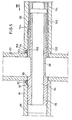
- Fig. 1 eine erste Ausführungsform einer Leitungskreuzung,
- Fig. 2 einen Schnitt gemäß der Linie II-II von Fig. 1,
- Fig. 3 ein zweites Ausführungsbeispiel einer Rohrkreuzung,
- Fig. 4 eine Ansicht gemäß Pfeil IV von Fig. 3,
- Fig. 5 eine dritte Ausführungsform einer Rohrkreuzung,
- Fig. 6 die Verbindungsbuchse von Fig. 5 und
- Fig. 7 eine Ansicht gemäß Pfeil VII von Fig. 5.
- Fig. 1 zeigt eine Kreuzungsstelle in einem Rohrleitungssystem, mit einem durchgehenden Rohr 10 und zwei aufstoßenden Rohren 12 und 14. In dem durchgehenden Rohr 10 ist eine Durchgangsbohrung 16 ausgebildet. Das Ende des aufstoßenden Rohres 12 ist mit einem Innengewinde 18 versehen, das Ende des aufstoßenden Rohres 14 mit einem Innengewinde 20. Zur Aufnahme von Dichtungs-O-Ringen 22, 24 sind die Enden der Rohre 12 bzw. 14 mit ringförmigen Ausnehmungen 26, 28 versehen. In das Ende des Rohres 12 ist eine Buchse 30, die mit einem Außengewinde versehen ist, eingeschraubt. Die Buchse 30 steht mit einem Abschnitt 32 aus dem Rohr 12 hervor. Der Abschnitt 32 hat eine Länge, die in etwa der Wandstärke des durchgehenden Rohres 10 entspricht. Die Buchse 30 ist mit Durchgangsöffnungen 34 versehen, die entweder koaxiale Bohrungen oder etwa halbkreisförmige Ringe darstellen können. Axial und zentrisch ist in der Buchse eine Bohrung 36 mit Innengewinde angeordnet, die zum Einschrauben eines Schraubenbolzens 38 dient.
- In das mit dem Innengewinde 20 versehene Ende des Rohres 14 ist eine Buchse 40 eingeschraubt, die mit einem Abschnitt 42 aus dem Rohr 14 hervorsteht. Die Buchse 42 ist mit Durchgangsbohrungen 44 versehen, die zur Durchleitung der Flüssigkeit dienen. Diese Durchgangsbohrungen können ebenfalls als etwa halbringförmige Durchlässe ausgebildet sein. Axial und zentral ist eine Durchgangsbohrung 46 in der Buchse 40 ausgebildet, durch die sich der Schraubenbolzen 38 erstrecken kann. Das Ende der Buchse dient als Widerlager für den beispielsweise mit einem Innensechskant versehenen Kopf 48 des Schraubenbolzens 38. Zum Anschließen der Rohre 12 und 14 an das Rohr 10 werden diese mit den Buchsen 30 bzw. 40 versehen, die Dichtungsringe 22 bzw. 24 werden in die sich zwischen den Rohrenden und den Buchsen ergebenden Ringnuten eingelegt und die Endabschnitte 32 bzw. 42 werden in die Durchgangsbohrung 16 in dem durchgehenden Rohr 10 eingesteckt. Durch das Rohr 14 wird mit einem entsprechend lang ausgebildeten Werkzeug der Schraubenbolzen 38 eingeführt, durch die Buchse 40 hindurchgesteckt und in die Bohrung 36 in der Buchse 30 eingeschraubt.
- Wenn keine Vermischung der durch die Rohre 12 und 14 strömenden Flüssigkeit mit der durch das Rohr 10 strömenden Flüssigkeit erfolgen soll, kann zwischen den Enden 32 und 42 der Buchsen 30 bzw. 40 eine Hülse 50 angebracht werden. Der Außendurchmesser der Hülse 50 ist geringer als der Innendurchmesser des Rohres 10, so daß die Flüssigkeit um die Hülse herum strömen kann. Die Endabschnitte der Buchsen können dabei innen konisch ausgebildet sein, so daß die Hülse 50 während des Zusammenziehens der Buchsen 30 und 40 in die Buchsenenden eingepreßt wird. Eine absolute Dichtigkeit zwischen den Enden der Hülse 50 und den Buchsen 30 bzw. 40 ist nicht erforderlich, da die strömenden Flüssigkeiten gleiche Beschaffenheit haben, so daß eine geringe Leckage unbedeutend ist.
- Fig. 2 zeigt einen Schnitt durch die Buchse 30, aus dem die Ausgestaltung der Durchgangsöffnungen durch die Buchse ersichtlich ist.
- Fig. 3 zeigt eine Kreuzungsstelle in einem Rohrleitungssystem, bei dem ein durchgehendes Rohr 60 mit zwei aufstoßenden Rohren 62 bzw. 64 verbunden wird. In dem Rohr 60 ist eine Durchgangsbohrung 66 ausgebildet, die Verbindung der Rohre 62 und 64 erfolgt über eine 67 einstückig ausgebildete Buchse/mit zwei Endabschnitten 68 und 70, die über einen mittleren Rohrabschnitt 72 miteinander verbunden sind. Die Enden der Rohre 62 und 64 sind wiederum mit Ausnehmungen versehen, in welche Dichtungsringe 74 eingelegt werden können. Der Endabschnitt 68 ist mit einem äußeren Linksgewinde versehen, während der Endabschnitt 70 mit einem äußeren Rechtsgewinde ausgebildet ist. Entsprechend sind die Innengewinde der Enden der Rohre 62 und 64 ausgebildet. Zur Verbindung der Rohre 62 und 64 mit dem Rohr 60 wird die Buchse 67 durch die Durchgangsbohrung 66 gesteckt, so daß sie beidseitig mit den Endabschnitten 68 bzw. 70 hervorsteht. Die Rohre 62 und 64 werden an diese Endabschnitte angesetzt und ein durch eines der Rohre 62 bzw. 64 geführtes Werkzeug greift in einen Innensechskant ,76 der am Ende der Endabschnitte 67 bzw. 70 ausgebildet ist. Durch Drehen der Buchse werden die Enden der Rohre 62 und 64 aufgeschraubt, bis sie an der Außenseite des durchgehenden Rohres 60 anstoßen. Der mittlere Rohrabschnitt 72 weist dabei wieder einen äusseren Durchmesser auf, der geringer ist als der innere Durchmesser des durchgehenden Rohres 60, so daß die Flüssigkeit in dem Rohr 60 um den inneren Rohrabschnitt 72 herumstreichen kann. Soll eine Durchmischung der durch die Rohre 60 bzw. 62 und 64 geführten Flüssigkeiten erfolgen, kann der innere Rohrabschnitt 72 mit Durchgangsbohrungen ausgebildet sein.
- Fig. 4 zeigt einen Blick auf den Endabschnitt 70 der Buchse 67, aus dem der Innensechskant 76 zum Ansetzen eines Imbusschlüssels versehen ist.
- Da während des Aufschraubens der Rohre 62 und 64 auf die Buchse 67 die O-Ringe 74 verletzt werden können, so daß Dichtungsprobleme zwischen den sich kreuzenden Rohren auftreten, zeigt Fig. 5 eine andere Ausführungsform einer Verbindungsbuchse, bei der die O-Ringe während der Verbindung geschützt sind. Fig. 5 zeigt ein durchgehendes Rohr 80, das mit einer Durchgangsbohrung 82 ausgebildet ist. Mit diesem Rohr 80 sind das Rohr 84 und das Rohr 86 verbunden. Das Rohr 84 ist an seinem Ende mit einem Innengewinde 88 ausgebildet und weist am äußeren Ende eine Ausnehmung 90 auf, in die ein O-Ring 92 eingelegt ist. In das Rohr 84 ist eine lange Buchse 94 eingeschraubt, deren Gestalt insbesondere aus Fig.6 zu ersehen ist. Die Buchse 94 besteht aus vier Abschnitten, nämlich einem Endabschnitt 96 zum Einschrauben in das Rohr 84, einem mittleren Rohrabschnitt 98, der sich durch das durchgehende Rohr 80 erstreckt, einem glatten Abschnitt 100, der im äußeren Endbereich des aufstoßenden Rohres 86 verläuft und einem mit einem Außengewinde versehenen Bereich 102, der sich an diesen glatten Bereich anschließt.
- Das aufstoßende Rohr 86 ist an seinem Ende mit einem Innengewinde 104 ausgebildet, in das eine Hilfsbuchse 106 eingeschraubt ist. Diese Hilfsbuchse, die eine glatte Innenfläche aufweist, steht über das Rohr 86 hervor und bildet mit einer Ausnehmung 108 im Ende des Rohres 86 eine Ringnut 110, in die ein O-Ring 112 zur Abdichtung zwischen dem Rohr 86 und dem Rohr 80 eingelegt ist. Eine auf das Außengewinde 102 des äußeren Abschnitts der Buchse 94 aufschraubbare Ringmutter 114 bewirkt den Zusammenhang der Buchsenteile mit den aufstoßenden Rohren und dem durchgehenden Rohr.
- Zum Zusammenbau der Rohre 84 und 86 mit dem Rohr 80 wird die Buchse 94 in das Rohr 84 eingeschraubt. Anschließend wird die Buchse durch die Durchgangsbohrung 82 in dem Rohr 80 hindurchgesteckt. Danach wird das mit der Hilfsbuchse 106 versehene Ende des Rohres 86 über die Bereiche 100 und 102 der Buchse 94 gesteckt, wobei der O-Ring 112 vorher in die Nut 110 eingelegt worden ist. Von der Seite des Rohres 86 wird jetzt die Ringmutter 114 eingeführt, die mit einem entsprechend lang ausgebildeten Werkzeug auf das Außengewinde des Bereichs 102 der Buchse 94 aufgeschraubt wird. Die Ringmutter 114 ist dazu, wie insbesondere aus Fig. 7 zu ersehen ist, mit einem Innensechskant 116 ausgebildet.
Claims (16)
Priority Applications (1)
| Application Number | Priority Date | Filing Date | Title |
|---|---|---|---|
| AT83102658T ATE23737T1 (de) | 1982-06-03 | 1983-03-17 | Schweissstellenfreie verbindung. |
Applications Claiming Priority (2)
| Application Number | Priority Date | Filing Date | Title |
|---|---|---|---|
| DE3220945 | 1982-06-03 | ||
| DE3220945A DE3220945C2 (de) | 1982-06-03 | 1982-06-03 | Schweißstellenfreie Verbindung |
Publications (2)
| Publication Number | Publication Date |
|---|---|
| EP0096175A1 true EP0096175A1 (de) | 1983-12-21 |
| EP0096175B1 EP0096175B1 (de) | 1986-11-20 |
Family
ID=6165229
Family Applications (1)
| Application Number | Title | Priority Date | Filing Date |
|---|---|---|---|
| EP83102658A Expired EP0096175B1 (de) | 1982-06-03 | 1983-03-17 | Schweissstellenfreie Verbindung |
Country Status (9)
| Country | Link |
|---|---|
| US (1) | US4614370A (de) |
| EP (1) | EP0096175B1 (de) |
| JP (1) | JPS5913182A (de) |
| KR (1) | KR880002489B1 (de) |
| AT (1) | ATE23737T1 (de) |
| CA (1) | CA1223615A (de) |
| DE (2) | DE3220945C2 (de) |
| HK (1) | HK40988A (de) |
| SG (1) | SG6988G (de) |
Cited By (2)
| Publication number | Priority date | Publication date | Assignee | Title |
|---|---|---|---|---|
| EP0691504A1 (de) * | 1994-05-24 | 1996-01-10 | Atelier D Société Cooperative | Anwendung von Muffenverbindungen für ein- oder mehrdimensionale rohrförmige Bewässerungssysteme |
| EP3640484A1 (de) * | 2018-10-16 | 2020-04-22 | RK Rose + Krieger GmbH Verbindungs- und Positioniersysteme | Verbindungsanordnung für mindestens zwei profilelemente |
Families Citing this family (9)
| Publication number | Priority date | Publication date | Assignee | Title |
|---|---|---|---|---|
| US4952092A (en) * | 1989-04-21 | 1990-08-28 | Standard Steel Rail Technology | Tubular railing system |
| US5094143A (en) * | 1990-10-24 | 1992-03-10 | Parker-Hannifin Corporation | Port mounted fluid control valve construction |
| JP3982117B2 (ja) * | 1999-05-31 | 2007-09-26 | 東芝ライテック株式会社 | 防水ソケット及び照明器具 |
| US20040051311A1 (en) | 2002-09-13 | 2004-03-18 | Nilsen Martin J. | Pipe nipple |
| US20090084740A1 (en) * | 2007-09-28 | 2009-04-02 | Ching-Yi Lin | Sectional rack for storage |
| JP4748612B2 (ja) * | 2008-10-21 | 2011-08-17 | 株式会社ツバキエマソン | 外筒取付構造 |
| CN102979791A (zh) * | 2012-04-24 | 2013-03-20 | 南车南京浦镇车辆有限公司 | 轨道车辆交叉扶手装配方法 |
| CN102966648A (zh) * | 2012-04-24 | 2013-03-13 | 南车南京浦镇车辆有限公司 | 轨道车辆交叉扶手隐形连接结构 |
| JP2020073770A (ja) * | 2020-01-22 | 2020-05-14 | Toto株式会社 | 水栓装置 |
Citations (4)
| Publication number | Priority date | Publication date | Assignee | Title |
|---|---|---|---|---|
| DE69935C (de) * | N. TVERSKOI, Maschinen-Ingenieur der Kaiserlich russischen Marine, und P. TVERSKAIA in St. Petersburg, Englischer Quai 22 | Rohrverbindung | ||
| FR1596253A (de) * | 1968-12-20 | 1970-06-15 | ||
| CH529963A (de) * | 1969-12-09 | 1972-10-31 | Sigvard Andersson Rune | Rohrverbindung und Verfahren zu ihrer Herstellung |
| DE2857662C2 (de) * | 1978-04-20 | 1982-04-01 | Josef Gartner & Co, 8883 Gundelfingen | Verbindungsvorrichtung zur schweißstellenfreien Verbindung in einer Temperierungseinrichtung für Fassadenwände |
Family Cites Families (6)
| Publication number | Priority date | Publication date | Assignee | Title |
|---|---|---|---|---|
| DE291986C (de) * | ||||
| US1825034A (en) * | 1927-04-13 | 1931-09-29 | Jr Albert J Weatherhead | Sectional pipe coupling |
| DE1757169U (de) * | 1957-10-01 | 1957-12-05 | E H D Kuehlerfabrik Ernst Hert | Industriekuehler. |
| US3425632A (en) * | 1967-02-27 | 1969-02-04 | William H Stout | Hollow pin slip coupler having sprinkler head |
| FR1589011A (de) * | 1968-10-09 | 1970-03-16 | ||
| US4210199A (en) * | 1978-06-14 | 1980-07-01 | Doucette Industries, Inc. | Heat exchange system |
-
1982
- 1982-06-03 DE DE3220945A patent/DE3220945C2/de not_active Expired
-
1983
- 1983-03-17 EP EP83102658A patent/EP0096175B1/de not_active Expired
- 1983-03-17 DE DE8383102658T patent/DE3367805D1/de not_active Expired
- 1983-03-17 AT AT83102658T patent/ATE23737T1/de not_active IP Right Cessation
- 1983-05-31 US US06/499,222 patent/US4614370A/en not_active Expired - Lifetime
- 1983-06-02 CA CA000429543A patent/CA1223615A/en not_active Expired
- 1983-06-02 JP JP58098744A patent/JPS5913182A/ja active Granted
- 1983-06-03 KR KR1019830002489A patent/KR880002489B1/ko not_active Expired
-
1988
- 1988-02-02 SG SG69/88A patent/SG6988G/en unknown
- 1988-06-02 HK HK409/88A patent/HK40988A/xx not_active IP Right Cessation
Patent Citations (4)
| Publication number | Priority date | Publication date | Assignee | Title |
|---|---|---|---|---|
| DE69935C (de) * | N. TVERSKOI, Maschinen-Ingenieur der Kaiserlich russischen Marine, und P. TVERSKAIA in St. Petersburg, Englischer Quai 22 | Rohrverbindung | ||
| FR1596253A (de) * | 1968-12-20 | 1970-06-15 | ||
| CH529963A (de) * | 1969-12-09 | 1972-10-31 | Sigvard Andersson Rune | Rohrverbindung und Verfahren zu ihrer Herstellung |
| DE2857662C2 (de) * | 1978-04-20 | 1982-04-01 | Josef Gartner & Co, 8883 Gundelfingen | Verbindungsvorrichtung zur schweißstellenfreien Verbindung in einer Temperierungseinrichtung für Fassadenwände |
Cited By (2)
| Publication number | Priority date | Publication date | Assignee | Title |
|---|---|---|---|---|
| EP0691504A1 (de) * | 1994-05-24 | 1996-01-10 | Atelier D Société Cooperative | Anwendung von Muffenverbindungen für ein- oder mehrdimensionale rohrförmige Bewässerungssysteme |
| EP3640484A1 (de) * | 2018-10-16 | 2020-04-22 | RK Rose + Krieger GmbH Verbindungs- und Positioniersysteme | Verbindungsanordnung für mindestens zwei profilelemente |
Also Published As
| Publication number | Publication date |
|---|---|
| US4614370A (en) | 1986-09-30 |
| JPH039357B2 (de) | 1991-02-08 |
| EP0096175B1 (de) | 1986-11-20 |
| SG6988G (en) | 1988-07-15 |
| ATE23737T1 (de) | 1986-12-15 |
| JPS5913182A (ja) | 1984-01-23 |
| KR880002489B1 (ko) | 1988-11-19 |
| DE3220945A1 (de) | 1983-12-08 |
| HK40988A (en) | 1988-06-10 |
| KR840005535A (ko) | 1984-11-14 |
| CA1223615A (en) | 1987-06-30 |
| DE3367805D1 (en) | 1987-01-08 |
| DE3220945C2 (de) | 1984-11-22 |
Similar Documents
| Publication | Publication Date | Title |
|---|---|---|
| EP0483751B1 (de) | Verbindungssystem | |
| DE3220945C2 (de) | Schweißstellenfreie Verbindung | |
| DE19831626C2 (de) | Rohrverbindung mit einem einem Rohrende angeformten Verbindungsabschnitt | |
| DE2631984A1 (de) | Rohrverschraubung mit anschweisstutzen | |
| EP0166203B1 (de) | Armatur für das Gas- und/oder Flüssigkeitsrohrnetz | |
| CH663832A5 (de) | Rohrschelle zum verbinden zweier rohrenden. | |
| DE3923579A1 (de) | Anschlussarmatur fuer rohre, insbesondere fuer kunststoffrohre | |
| DE2230909C2 (de) | Mehrwegeventil | |
| DE2816132A1 (de) | Schraubverbindung | |
| DE9107311U1 (de) | Schweißmuffe | |
| CH612748A5 (en) | Hot water radiator | |
| EP0702186B1 (de) | Anschluss eines Gerätes an eine rohrförmige Armatur | |
| DE3442424C2 (de) | Gelenkige Verbindungseinrichtung für Rohre oder hydraulische Geräte | |
| DE2412697A1 (de) | Rohrverbindung | |
| DE3305526A1 (de) | Fernbetaetigbare klemmverbindungs-vorrichtung fuer zwei rohre oder zylinderische behaelter | |
| DE3532180C1 (en) | Device for shutting off a pipeline, especially a drinking-water line | |
| DE69832316T2 (de) | Rohranschluss für konzentrische Röhre, der aus zwei koaxialen Rohrbogen besteht | |
| DE4235723A1 (de) | Mehrwege-Kugelhahn | |
| AT390661B (de) | Anschlusseinrichtung fuer das anschliessen von heizkoerpern | |
| EP0630028B1 (de) | Thermische Schutzhülse für Kernreaktordruckbehälterrohrstutzen | |
| DE19637902C2 (de) | Ventil-Rohrsystem | |
| CH461898A (de) | Abdichtende Rohrverbindung für Rohre, vorzugsweise aus Kupfer | |
| DE2146726A1 (de) | Harzgebundenes glasfadenrohr | |
| DE19641926C2 (de) | Vorrichtung zur Sanierung von Gasleitungen | |
| EP1239206B1 (de) | Klemmflansch-Verbindung |
Legal Events
| Date | Code | Title | Description |
|---|---|---|---|
| PUAI | Public reference made under article 153(3) epc to a published international application that has entered the european phase |
Free format text: ORIGINAL CODE: 0009012 |
|
| AK | Designated contracting states |
Designated state(s): AT BE CH DE FR GB IT LI LU NL SE |
|
| 17P | Request for examination filed |
Effective date: 19831019 |
|
| GRAA | (expected) grant |
Free format text: ORIGINAL CODE: 0009210 |
|
| AK | Designated contracting states |
Kind code of ref document: B1 Designated state(s): AT BE CH DE FR GB IT LI LU NL SE |
|
| PG25 | Lapsed in a contracting state [announced via postgrant information from national office to epo] |
Ref country code: IT Free format text: LAPSE BECAUSE OF FAILURE TO SUBMIT A TRANSLATION OF THE DESCRIPTION OR TO PAY THE FEE WITHIN THE PRESCRIBED TIME-LIMIT;WARNING: LAPSES OF ITALIAN PATENTS WITH EFFECTIVE DATE BEFORE 2007 MAY HAVE OCCURRED AT ANY TIME BEFORE 2007. THE CORRECT EFFECTIVE DATE MAY BE DIFFERENT FROM THE ONE RECORDED. Effective date: 19861120 Ref country code: FR Free format text: THE PATENT HAS BEEN ANNULLED BY A DECISION OF A NATIONAL AUTHORITY Effective date: 19861120 Ref country code: BE Effective date: 19861120 |
|
| REF | Corresponds to: |
Ref document number: 23737 Country of ref document: AT Date of ref document: 19861215 Kind code of ref document: T |
|
| PG25 | Lapsed in a contracting state [announced via postgrant information from national office to epo] |
Ref country code: SE Effective date: 19861130 |
|
| REF | Corresponds to: |
Ref document number: 3367805 Country of ref document: DE Date of ref document: 19870108 |
|
| PG25 | Lapsed in a contracting state [announced via postgrant information from national office to epo] |
Ref country code: AT Effective date: 19870317 |
|
| PG25 | Lapsed in a contracting state [announced via postgrant information from national office to epo] |
Ref country code: LU Free format text: LAPSE BECAUSE OF NON-PAYMENT OF DUE FEES Effective date: 19870331 Ref country code: LI Effective date: 19870331 Ref country code: CH Effective date: 19870331 |
|
| EN | Fr: translation not filed | ||
| PLBE | No opposition filed within time limit |
Free format text: ORIGINAL CODE: 0009261 |
|
| STAA | Information on the status of an ep patent application or granted ep patent |
Free format text: STATUS: NO OPPOSITION FILED WITHIN TIME LIMIT |
|
| 26N | No opposition filed | ||
| REG | Reference to a national code |
Ref country code: CH Ref legal event code: PL |
|
| PGFP | Annual fee paid to national office [announced via postgrant information from national office to epo] |
Ref country code: NL Payment date: 19990322 Year of fee payment: 17 |
|
| PGFP | Annual fee paid to national office [announced via postgrant information from national office to epo] |
Ref country code: DE Payment date: 19990527 Year of fee payment: 17 |
|
| PGFP | Annual fee paid to national office [announced via postgrant information from national office to epo] |
Ref country code: GB Payment date: 20000229 Year of fee payment: 18 |
|
| PG25 | Lapsed in a contracting state [announced via postgrant information from national office to epo] |
Ref country code: NL Free format text: LAPSE BECAUSE OF NON-PAYMENT OF DUE FEES Effective date: 20001001 |
|
| NLV4 | Nl: lapsed or anulled due to non-payment of the annual fee |
Effective date: 20001001 |
|
| PG25 | Lapsed in a contracting state [announced via postgrant information from national office to epo] |
Ref country code: DE Free format text: LAPSE BECAUSE OF NON-PAYMENT OF DUE FEES Effective date: 20010103 |
|
| PG25 | Lapsed in a contracting state [announced via postgrant information from national office to epo] |
Ref country code: GB Free format text: LAPSE BECAUSE OF NON-PAYMENT OF DUE FEES Effective date: 20010317 |
|
| GBPC | Gb: european patent ceased through non-payment of renewal fee |
Effective date: 20010317 |