EP0096247A2 - Dispositif pour l'obtention en operation d'une valeur d'humidité pour la plaque rotative d'impression dans une machine d'impression "offset" - Google Patents
Dispositif pour l'obtention en operation d'une valeur d'humidité pour la plaque rotative d'impression dans une machine d'impression "offset" Download PDFInfo
- Publication number
- EP0096247A2 EP0096247A2 EP83104857A EP83104857A EP0096247A2 EP 0096247 A2 EP0096247 A2 EP 0096247A2 EP 83104857 A EP83104857 A EP 83104857A EP 83104857 A EP83104857 A EP 83104857A EP 0096247 A2 EP0096247 A2 EP 0096247A2
- Authority
- EP
- European Patent Office
- Prior art keywords
- radiation
- dampening solution
- measuring
- measuring spot
- photoelectric converter
- Prior art date
- Legal status (The legal status is an assumption and is not a legal conclusion. Google has not performed a legal analysis and makes no representation as to the accuracy of the status listed.)
- Granted
Links
Images

Classifications
-
- B—PERFORMING OPERATIONS; TRANSPORTING
- B41—PRINTING; LINING MACHINES; TYPEWRITERS; STAMPS
- B41F—PRINTING MACHINES OR PRESSES
- B41F33/00—Indicating, counting, warning, control or safety devices
- B41F33/0063—Devices for measuring the thickness of liquid films on rollers or cylinders
-
- G—PHYSICS
- G01—MEASURING; TESTING
- G01N—INVESTIGATING OR ANALYSING MATERIALS BY DETERMINING THEIR CHEMICAL OR PHYSICAL PROPERTIES
- G01N21/00—Investigating or analysing materials by the use of optical means, i.e. using sub-millimetre waves, infrared, visible or ultraviolet light
- G01N21/17—Systems in which incident light is modified in accordance with the properties of the material investigated
- G01N21/47—Scattering, i.e. diffuse reflection
- G01N21/4738—Diffuse reflection, e.g. also for testing fluids, fibrous materials
-
- G—PHYSICS
- G01—MEASURING; TESTING
- G01N—INVESTIGATING OR ANALYSING MATERIALS BY DETERMINING THEIR CHEMICAL OR PHYSICAL PROPERTIES
- G01N21/00—Investigating or analysing materials by the use of optical means, i.e. using sub-millimetre waves, infrared, visible or ultraviolet light
- G01N21/17—Systems in which incident light is modified in accordance with the properties of the material investigated
- G01N21/25—Colour; Spectral properties, i.e. comparison of effect of material on the light at two or more different wavelengths or wavelength bands
- G01N21/31—Investigating relative effect of material at wavelengths characteristic of specific elements or molecules, e.g. atomic absorption spectrometry
- G01N21/35—Investigating relative effect of material at wavelengths characteristic of specific elements or molecules, e.g. atomic absorption spectrometry using infrared light
- G01N21/3554—Investigating relative effect of material at wavelengths characteristic of specific elements or molecules, e.g. atomic absorption spectrometry using infrared light for determining moisture content
-
- G—PHYSICS
- G01—MEASURING; TESTING
- G01N—INVESTIGATING OR ANALYSING MATERIALS BY DETERMINING THEIR CHEMICAL OR PHYSICAL PROPERTIES
- G01N21/00—Investigating or analysing materials by the use of optical means, i.e. using sub-millimetre waves, infrared, visible or ultraviolet light
- G01N21/84—Systems specially adapted for particular applications
- G01N21/86—Investigating moving sheets
Definitions
- the invention relates to a device for operationally recording a measure of the amount of dampening solution on a measuring spot on the rotating printing plate in offset printing machines.
- This device is equipped with a radiation source which emits radiation pulses in the wavelength range of an absorption wavelength of the dampening solution onto the measuring spot of the printing plate. Outside the angle of reflection of the radiation pulses reflected from the plate onto the measurement spot, radiation is fed to a first photoelectric converter, which captures these radiation pulses and quantitatively converts them into first electrical signals, which are then used in an evaluation circuit to derive a value for the amount of dampening solution.
- Such a device is known for example from DE-PS 1 303 819.
- the known device uses further radiation pulses in a wavelength range in which the radiation is supposed to be influenced only minimally by the dampening solution layer, and by forming quotients with the radiation pulse amplitudes of the two different wavelengths, which are influenced differently by the dampening solution layer, in the form of the electrical one Signals are attempted to draw conclusions about the amount of dampening solution.
- a measuring head that emits radiation pulses in the wavelength range of an absorption wavelength of the dampening solution from a radiation source first directs these pulses onto the same but dry measuring spot on the printing plate, and the photoelectric transducer converts the remitted radiation reaching it outside the angle of reflection into a so-called "dry signal", which is now stored in a working memory of the evaluation device and is compared to the electrical signal of the converter during the operational measurements on the moist plate, from which a measure for the Amount of dampening solution can be derived.
- the procedure according to the invention is based on a knowledge which the applicant has determined to be valid with sufficient accuracy at least for a number of common printing plate types, according to which dei indicators (vector field of the remitted radiation components of a beam impinging on a measuring spot) for all measuring points on a plate in the dry state and also for different wear conditions are geometrically similar and the indicatrices experience a geometrically similar reduction under the influence of the dampening solution.
- dei indicators vector field of the remitted radiation components of a beam impinging on a measuring spot
- the indicators of dry measuring points differ considerably in size at different locations on the plate, but they remain similar to one another.
- the evaluation can be carried out with related values by providing a second photoelectric converter which receives radiation pulses from the radiation source directly, that is to say without going through the printing plate , whereby its output value as reference signal is in each case compared with the corresponding output signal of the first photoelectric converter using the quotient method, and the link for deriving the value for the amount of dampening solution is then made using these related values.
- the radiation which is diffusely remitted from the measurement spot can be recorded with the aid of an optical system which images the measurement spot onto the first photoelectric converter, which is preferably an elliptically curved mirror surface, the first focus of which coincides with the measurement spot and the second focus of which coincides with the photoelectric converter.
- the resulting yield enables a sufficient signal-to-noise ratio even with extremely short radiation pulses, so that measurement errors due to external interference can be excluded.
- Influencing the measurement by means of a measuring apparatus against paper dust, paint, etc. final cutting disc in the radiation inlet and outlet window of the measuring head are avoided by the anti-reflective coating at least for the wavelength range of the measuring radiation.
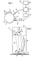
- FIG. 1 shows schematically the plate cylinder 11 of a generally known and therefore not shown overall printing unit of an offset rotary printing press, on which a printing plate 12 is mounted in the usual way.
- a measuring head 17 is mounted in the printing machine, preferably traversing in the direction parallel to the axis of the plate cylinder 11, which is connected by means of two connecting lines 18, 19 to an evaluation circuit 20, which is surrounded in its entirety by a dashed frame .
- This evaluation circuit 20 contains a computer unit 21, a working memory 22 and a display 23 on which the measured amount of dampening solution is displayed in a suitable form.
- a longitudinal section through the measuring head 17 is shown in simplified form in FIG.
- the longitudinal section is placed in a radial plane of the plate cylinder 11.
- a pulse light source 26 is attached, which on here is not interested in more detail synchronously with the passing of a measuring spot 27 on the pressure plate 12 and emits a light pulse, part of which as a measuring beam 28 via a mirror 29 onto the measuring spot 27 and another part as a reference beam 30 directly onto a reference detector 31 upstream filter 32 is directed.
- the filter 32 has a pass band of a wavelength which corresponds to the measuring wavelength and, as is known per se, can be an absorption wavelength of the dampening solution or a wavelength which is deliberately adjacent.
- a remitted radiation component 33 located outside the reflection angle of the measurement beam 28 directed at the measurement spot 27 enters the opening 25 of the housing 24 of the measurement head 17 and is concentrated by a mirror 34 on a further photoelectric measurement transducer 35, which is likewise preceded by a filter 36, which has the same passband as the filter 32.
- the mirror 34 is designed as an ellipse mirror and is arranged in such a way that the first focal point of the ellipse falls in the measurement spot 27 and the second focal point falls on the sensitive surface of the measurement detector 35. There is obtained with this o p arrangement schematically an excellent yield of the light reflected within a predetermined angle from the reflectance measurement spot 27 radiation.
- a separating disk 37 which covers the opening 25 and is permeable to measurement and remission radiation is antireflective at least for this radiation, so that it has no optical properties affecting the measurement process.
- the evaluation circuit which is shown in more detail in FIG. 3, contains in its computer section 21 a divider 41, adders / sub-radiators 42 and 43 and a further divider 44 connected downstream of the latter and is working memory 22 connected, which is composed of the partial memories 221 for the related gloss signal E G / R G , 222 for the related crosstalk signal E ü / R Ü and 223 for the related dry signal E tr / R tr .
- the type of control for the inclusion of the related values in the respective memories and their output in the calculation process are not discussed in detail here, since such measures are familiar to the person skilled in the art.
- the value representing the measure of the dampening solution amount E * for example for controlling the dampening system of the printing press, can be taken off and it is also fed to the display device 23.
- the operation of the measuring device is as follows.
- radiation pulses are emitted by the radiation source 26, which generate 35 electrical pulses E tr at the output of the measuring detector and 31 electrical pulses R tr at the output of the reference detector, which via lines 18 and 19 of the evaluation circuit 20 fed and stored there after formation of the related value E tr / R tr in the divider 41 for the subsequent print run in the working memory 223.
- the printing plate can be provided with an excess of dampening solution, the signals then recorded and emitted by the detectors 35 and 31 being the gloss signal EG and the reference signal R G , respectively, which likewise occur in the divider 41 in the working memory after the related value E G / R G has been formed 221 can be saved.
- crosstalk signals can be recorded by placing a black body underneath the machine instead of the measurement spot 27, as a result of which non-switchable, measurement head-inherent quantities E ü and R ü are recorded, which after formation of the related value E ü / R ü in the divider 41 in the working memory 222 stored and taken into account in the subsequent operational measurements.
- the actual dampening solution quantity measurement takes place during operation of the printing press with a plate dampened by the dampening unit 15 via the dampening solution application roller 14, the radiation source 26 being controlled with the aid of a synchronization which is not to be explained here in detail and which is obvious to the person skilled in the art in such a way that with each individual plate cylinder revolution or after several a flash of radiation is emitted and a measuring beam 28 is directed onto the measuring spot 27.
- the signals E and R emitted by the measuring and reference detectors 35 and 31 are converted into a measure for the amount of dampening solution E * in the computer unit 21 of the evaluation circuit 20, taking into account all of the above-mentioned and previously recorded and stored variables according to the following equation. processed.
Landscapes
- Physics & Mathematics (AREA)
- Health & Medical Sciences (AREA)
- Life Sciences & Earth Sciences (AREA)
- Chemical & Material Sciences (AREA)
- Analytical Chemistry (AREA)
- Biochemistry (AREA)
- General Health & Medical Sciences (AREA)
- General Physics & Mathematics (AREA)
- Immunology (AREA)
- Pathology (AREA)
- Inking, Control Or Cleaning Of Printing Machines (AREA)
- Rotary Presses (AREA)
- Investigating Or Analysing Materials By Optical Means (AREA)
Applications Claiming Priority (2)
| Application Number | Priority Date | Filing Date | Title |
|---|---|---|---|
| DE3220282 | 1982-05-28 | ||
| DE3220282A DE3220282C3 (de) | 1982-05-28 | 1982-05-28 | Vorrichtung zum betrieblichen Erfassen eines Maßes für die Feuchtmittelmenge auf der rotierenden Druckplatte in Offset-Druckmaschinen |
Publications (3)
| Publication Number | Publication Date |
|---|---|
| EP0096247A2 true EP0096247A2 (fr) | 1983-12-21 |
| EP0096247A3 EP0096247A3 (en) | 1984-10-03 |
| EP0096247B1 EP0096247B1 (fr) | 1988-01-07 |
Family
ID=6164826
Family Applications (1)
| Application Number | Title | Priority Date | Filing Date |
|---|---|---|---|
| EP83104857A Expired EP0096247B1 (fr) | 1982-05-28 | 1983-05-17 | Dispositif pour l'obtention en operation d'une valeur d'humidité pour la plaque rotative d'impression dans une machine d'impression "offset" |
Country Status (3)
| Country | Link |
|---|---|
| US (1) | US4565450A (fr) |
| EP (1) | EP0096247B1 (fr) |
| DE (1) | DE3220282C3 (fr) |
Cited By (3)
| Publication number | Priority date | Publication date | Assignee | Title |
|---|---|---|---|---|
| EP0177921A3 (en) * | 1984-10-08 | 1989-01-11 | Dai Nippon Insatsu Kabushiki Kaisha | Method and device for measuring the quantity of water dampening the face of an offset printing plate |
| US7684523B2 (en) | 2005-09-28 | 2010-03-23 | Lg Electronics Inc. | Method and apparatus for channel estimation |
| CN106004038A (zh) * | 2016-05-13 | 2016-10-12 | 安庆市津海工业产品设计有限公司 | 一种上光机的快速烘干抽检装置 |
Families Citing this family (16)
| Publication number | Priority date | Publication date | Assignee | Title |
|---|---|---|---|---|
| DE3326698A1 (de) * | 1983-07-23 | 1985-02-07 | Heidelberger Druckmaschinen Ag, 6900 Heidelberg | Vorrichtung zur zonenweisen messtechnischen kontrolle der feuchtmittelfuehrung im druckwerk einer offsetdruckmaschine |
| DE3414573A1 (de) * | 1984-04-17 | 1985-10-24 | grapho metronic Meß- und Regeltechnik GmbH & Co, 8000 München | Verfahren zur messung der feuchtmittelschichtdicke auf offsetdruckplatten |
| DE3909401C2 (de) * | 1989-03-22 | 1994-02-10 | Heidelberger Druckmasch Ag | Verfahren zur Festlegung eines Meßortes für die Feuchtmittel-Schichtdickenbestimmung einer Offset-Druckplatte |
| US5078497A (en) * | 1989-08-25 | 1992-01-07 | Xerox Corporation | Densitometer for a liquid developer material |
| DE4106082A1 (de) * | 1990-04-26 | 1991-10-31 | Heidelberger Druckmasch Ag | Verfahren und vorrichtung zum positionieren einer sensoreinrichtung |
| AT401112B (de) * | 1993-11-12 | 1996-06-25 | Andritz Patentverwaltung | Verfahren und vorrichtung zur steuerung bzw. regelung eines fest-flüssig-trennverfahrens |
| DE4444269A1 (de) * | 1993-12-20 | 1995-06-22 | Ryobi Co | Feuchtevolumen-Steuerungsvorrichtung für eine Offsetpresse |
| US5592880A (en) * | 1993-12-30 | 1997-01-14 | Heidelberger Druckmaschinen | Method of supplying or feeding dampening solution |
| DE4436582C2 (de) * | 1994-10-13 | 1998-07-30 | Heidelberger Druckmasch Ag | Verfahren zur Regelung einer Feuchtmittelmenge für eine Druckform einer laufenden Offsetrotationsdruckmaschine |
| US6982794B1 (en) * | 1995-06-07 | 2006-01-03 | The Boeing Company | Directional reflectometer |
| US5963333A (en) * | 1996-09-12 | 1999-10-05 | Color Savvy Systems Limited | Color sensor |
| AUPQ611200A0 (en) * | 2000-03-09 | 2000-03-30 | Commonwealth Scientific And Industrial Research Organisation | Determination of change in thickness of dampening solution on offset printing rollers |
| US6457801B1 (en) | 2001-06-27 | 2002-10-01 | Lexmark International, Inc. | Method and apparatus for measuring ink dry time |
| EP1743148B1 (fr) * | 2004-05-05 | 2010-03-03 | X-Rite, Inc. | Spectrophotometre a poursuite automatique |
| US7522281B2 (en) | 2004-12-20 | 2009-04-21 | Heidelberger Druckmaschinen Ag | Apparatus and method for detecting moisture in a printing plate exposer |
| SE532397C2 (sv) * | 2008-10-09 | 2010-01-12 | Microfluid Ab | Vätskefilmmätare |
Family Cites Families (20)
| Publication number | Priority date | Publication date | Assignee | Title |
|---|---|---|---|---|
| DE1303819C2 (de) * | 1964-05-29 | 1973-07-12 | Vorrichtung zum messen einer schichtdicke auf oberflaechen | |
| JPS4837397B1 (fr) * | 1968-08-22 | 1973-11-10 | ||
| GB1404573A (en) * | 1971-07-26 | 1975-09-03 | Vickers Ltd | Sensing of liquids on surfaces |
| US3748046A (en) * | 1971-12-13 | 1973-07-24 | Harris Intertype Corp | Measurement of reflection density |
| DE2214721B1 (de) * | 1972-03-25 | 1973-06-14 | Heidelberger Druckmaschinen Ag, 6900 Heidelberg | Verfahren und vorrichtung zum selbsttaetigen ausregeln von schwankungen der farb- und feuchtfluessigkeitsfuehrung an offsetmaschinen |
| US4052937A (en) * | 1972-09-12 | 1977-10-11 | Vickers Limited | Printing plate water sensing means and method |
| US3832065A (en) * | 1973-03-23 | 1974-08-27 | Xerox Corp | Drum track detector |
| US3874799A (en) * | 1973-06-01 | 1975-04-01 | Color Control Inc | Method and apparatus for color spectrophotometry |
| IT1033240B (it) * | 1974-03-14 | 1979-07-10 | Grapho Metronic Gmbh & Co | Umidificatore in una macchina stampatrice offset con un dispositivo per la regolazione del quantitativo d acqua sulla piastra |
| DE2554086A1 (de) * | 1975-12-02 | 1977-06-16 | Ibm Deutschland | Verfahren zur analyse und/oder zur ortsbestimmung von kanten |
| DE2627753C2 (de) * | 1976-06-21 | 1983-09-01 | Leybold-Heraeus GmbH, 5000 Köln | Anordnung zur Dickenmessung und -steuerung optisch wirksamer Dünnschichten |
| US4124803A (en) * | 1976-12-22 | 1978-11-07 | Kenneth Bowers | Surface finish monitor |
| DE2729576A1 (de) * | 1977-06-28 | 1979-01-11 | Siemens Ag | Vorrichtung zur umfangsmessung strangfoermigen gutes |
| DE2736663C3 (de) * | 1977-08-13 | 1985-05-15 | Heidelberger Druckmaschinen Ag, 6900 Heidelberg | Vorrichtung zur Ermittlung des Feucht- und Farbgleichgewichts bei Offsetdruckwerken |
| FR2437621A1 (fr) * | 1978-09-29 | 1980-04-25 | Buehler Ag Geb | Procede et dispositif de mesure de la blancheur d'une farine et leur application au controle de l'homogeneite d'une charge de farine |
| IT1108255B (it) * | 1978-10-24 | 1985-12-02 | Fiat Spa | Procedimento e dispositivo per il controllo della rugosita della superficie di un pezzo che ha subito una lavorazione meccanica |
| US4455090A (en) * | 1979-07-26 | 1984-06-19 | The Wiggins Teape Group Limited | Apparatus for measuring surface reflectance characteristics |
| DE2947791C2 (de) * | 1979-11-28 | 1985-04-18 | Licentia Patent-Verwaltungs-Gmbh, 6000 Frankfurt | Einrichtung zur Farbüberwachung von bogen- oder bahnförmigen, in Bewegung befindlichen Materialien, insbesondere der Druckmaterialien von Druckmaschinen |
| DE2950650A1 (de) * | 1979-12-15 | 1981-06-19 | M.A.N.- Roland Druckmaschinen AG, 6050 Offenbach | Vorrichtung zur opto- elektronischen messung der flaechendeckung einer offset-druckplatte oder einer der offset-druckplattenherstellung dienenden druckvorlage |
| US4360275A (en) * | 1980-08-11 | 1982-11-23 | Litton Systems Inc. | Device for measurement of optical scattering |
-
1982
- 1982-05-28 DE DE3220282A patent/DE3220282C3/de not_active Expired - Lifetime
-
1983
- 1983-05-17 EP EP83104857A patent/EP0096247B1/fr not_active Expired
- 1983-05-25 US US06/497,828 patent/US4565450A/en not_active Expired - Fee Related
Cited By (3)
| Publication number | Priority date | Publication date | Assignee | Title |
|---|---|---|---|---|
| EP0177921A3 (en) * | 1984-10-08 | 1989-01-11 | Dai Nippon Insatsu Kabushiki Kaisha | Method and device for measuring the quantity of water dampening the face of an offset printing plate |
| US7684523B2 (en) | 2005-09-28 | 2010-03-23 | Lg Electronics Inc. | Method and apparatus for channel estimation |
| CN106004038A (zh) * | 2016-05-13 | 2016-10-12 | 安庆市津海工业产品设计有限公司 | 一种上光机的快速烘干抽检装置 |
Also Published As
| Publication number | Publication date |
|---|---|
| DE3220282C2 (de) | 1987-01-08 |
| EP0096247B1 (fr) | 1988-01-07 |
| EP0096247A3 (en) | 1984-10-03 |
| DE3220282A1 (de) | 1983-12-01 |
| US4565450A (en) | 1986-01-21 |
| DE3220282C3 (de) | 1995-05-18 |
Similar Documents
| Publication | Publication Date | Title |
|---|---|---|
| DE3220282C3 (de) | Vorrichtung zum betrieblichen Erfassen eines Maßes für die Feuchtmittelmenge auf der rotierenden Druckplatte in Offset-Druckmaschinen | |
| DE3833602C2 (fr) | ||
| EP0098423B1 (fr) | Spectromètre à réseau | |
| DE3010576C2 (fr) | ||
| DE19912500A1 (de) | Verfahren und Vorrichtung zum Bestimmen von Eigenschaften einer laufenden Materialbahn | |
| DE2935716A1 (de) | Verfahren und vorrichtung zum messen der dicke eines films durch ausnutzung von infrarot-interferenzerscheinungen | |
| DE2736663C3 (de) | Vorrichtung zur Ermittlung des Feucht- und Farbgleichgewichts bei Offsetdruckwerken | |
| DE19830395A1 (de) | Verfahren zur berührungslosen Messung von strangförmigem Fasergut | |
| CH669401A5 (fr) | ||
| DE2456566C2 (fr) | ||
| DE2741732C2 (de) | Schichtgerät zur Herstellung von Transversalschichtbildern | |
| DE3102450C2 (fr) | ||
| DE2600266A1 (de) | Anordnung zur ermittlung der absorption einer strahlung | |
| DE68921425T2 (de) | Optische Einrichtung für die Prüfung des Endes von Zigaretten. | |
| DE4427605A1 (de) | Verfahren und Vorrichtung zum Bestimmen des Gewichts stabförmiger Artikel der tabakverarbeitenden Industrie | |
| DE3752014T2 (de) | Verfahren und Anordnung zur laufenden Kennzeichnung einer Blatt Bildung. | |
| DE3539977C2 (fr) | ||
| DE69417376T2 (de) | Hochauflösendes und Hochgeschwindigkeits-Filmdickemessverfahren und Vorrichtung dazu | |
| DE2803380A1 (de) | Vorrichtung zur aufbringung von testbelichtungen | |
| DE3118560C2 (de) | Meßeinrichtung zur Bestimmung von Augenbrechungsfehlern | |
| WO1998034090A1 (fr) | Procede et dispositif pour mesurer la profondeur de profil d'un pneu de vehicule | |
| DE3800360C2 (de) | Verfahren zum Prüfen der Innenseite einer Floppydisk-Hülle | |
| DE102018100500A1 (de) | Vorrichtung und Verfahren zum Prüfen von stabförmigen Artikeln der Tabak verarbeitenden Industrie | |
| DE2618387A1 (de) | Film-abtastgeraet | |
| DE69522081T2 (de) | Vorrichtung zur Qualitäts- und Kontinuitätskontrolle eines auf eine Oberfläche aufgebrachten Streifens |
Legal Events
| Date | Code | Title | Description |
|---|---|---|---|
| PUAI | Public reference made under article 153(3) epc to a published international application that has entered the european phase |
Free format text: ORIGINAL CODE: 0009012 |
|
| AK | Designated contracting states |
Designated state(s): CH FR GB LI SE |
|
| PUAL | Search report despatched |
Free format text: ORIGINAL CODE: 0009013 |
|
| AK | Designated contracting states |
Designated state(s): CH FR GB LI SE |
|
| 17P | Request for examination filed |
Effective date: 19841120 |
|
| GRAA | (expected) grant |
Free format text: ORIGINAL CODE: 0009210 |
|
| AK | Designated contracting states |
Kind code of ref document: B1 Designated state(s): CH FR GB LI SE |
|
| PG25 | Lapsed in a contracting state [announced via postgrant information from national office to epo] |
Ref country code: FR Free format text: LAPSE BECAUSE OF NON-PAYMENT OF DUE FEES Effective date: 19880107 |
|
| PG25 | Lapsed in a contracting state [announced via postgrant information from national office to epo] |
Ref country code: SE Effective date: 19880131 |
|
| EN | Fr: translation not filed | ||
| GBV | Gb: ep patent (uk) treated as always having been void in accordance with gb section 77(7)/1977 [no translation filed] | ||
| PLBI | Opposition filed |
Free format text: ORIGINAL CODE: 0009260 |
|
| 26 | Opposition filed |
Opponent name: KOENIG & BAUER AKTIENGESELLSCHAFT Effective date: 19880930 |
|
| REG | Reference to a national code |
Ref country code: CH Ref legal event code: PL |
|
| RDAG | Patent revoked |
Free format text: ORIGINAL CODE: 0009271 |
|
| STAA | Information on the status of an ep patent application or granted ep patent |
Free format text: STATUS: PATENT REVOKED |
|
| GBPR | Gb: patent revoked under art. 102 of the ep convention designating the uk as contracting state | ||
| 27W | Patent revoked |
Effective date: 19890706 |