EP0096268A2 - Organe d'arrêt, en particulier vanne à tiroir - Google Patents
Organe d'arrêt, en particulier vanne à tiroir Download PDFInfo
- Publication number
- EP0096268A2 EP0096268A2 EP83105026A EP83105026A EP0096268A2 EP 0096268 A2 EP0096268 A2 EP 0096268A2 EP 83105026 A EP83105026 A EP 83105026A EP 83105026 A EP83105026 A EP 83105026A EP 0096268 A2 EP0096268 A2 EP 0096268A2
- Authority
- EP
- European Patent Office
- Prior art keywords
- shut
- dead space
- piston
- additional valve
- interior
- Prior art date
- Legal status (The legal status is an assumption and is not a legal conclusion. Google has not performed a legal analysis and makes no representation as to the accuracy of the status listed.)
- Withdrawn
Links
Images


Classifications
-
- F—MECHANICAL ENGINEERING; LIGHTING; HEATING; WEAPONS; BLASTING
- F16—ENGINEERING ELEMENTS AND UNITS; GENERAL MEASURES FOR PRODUCING AND MAINTAINING EFFECTIVE FUNCTIONING OF MACHINES OR INSTALLATIONS; THERMAL INSULATION IN GENERAL
- F16K—VALVES; TAPS; COCKS; ACTUATING-FLOATS; DEVICES FOR VENTING OR AERATING
- F16K3/00—Gate valves or sliding valves, i.e. cut-off apparatus with closing members having a sliding movement along the seat for opening and closing
- F16K3/02—Gate valves or sliding valves, i.e. cut-off apparatus with closing members having a sliding movement along the seat for opening and closing with flat sealing faces; Packings therefor
Definitions
- the invention relates to a shut-off device, in particular a gate valve, for gaseous, preferably condensable media, with a shut-off body which can be moved in a housing and which, in the closed position, separates the inflow side of the shut-off device from the outflow side, in the open position, on the other hand, connects it, and with an existing one in the interior of the shut-off device Dead space.
- a shut-off device in particular a gate valve, for gaseous, preferably condensable media
- shut-off elements in particular gate valves
- accumulations of liquid form in the deepest region of the housing during operation with condensable, vaporous media, in particular steam, or other liquid-carrying gaseous media This applies in particular to the shut-off device in the closed position. After opening the shut-off device, these liquid accumulations are often largely carried away or dried out by the medium flowing through. However, this only applies to shut-off devices in the normal installation position, i.e. with the shut-off body and moving vertically vertically arranged operating spindle.
- shut-off device mainly in the form of a shut-off valve
- a shut-off device mainly in the form of a shut-off valve
- gate valves that are installed in a normal installation position with a vertical spindle in high-pressure steam lines.
- these high-pressure shut-off devices have strongly bulged housing parts to increase their strength. the boss..Die to an increase of the dead spaces in such large dead spaces accumulating liquid or can Kondensatmen en g in particular when operating with high-pressure steam to interference and / or cause damage.
- the prescribed mode of operation of the system in which the shut-off element is inserted prevents the liquid accumulation from drying out gradually after the opening of the shut-off element.
- the invention is therefore based on the object of specifying a shut-off device of the type mentioned, the dead space of which is automatically emptied of accumulations of liquid in a simple and safe manner during the opening process.
- the shut-off device should continue to be universally applicable and fully meet operational requirements, particularly with regard to use at high pressures.
- the shut-off device has at least one additional valve in its housing, which is switched into a bvrass leading from the inflow side through the dead space to the outflow side and is connected for control with the shut-off body in such a way that the additional valve in Closed position of the shut-off body is also closed is, on the other hand, is opened during the opening movement of the shut-off body before a release or at least before a substantial release of the shut-off device flow.
- the dead space is therefore part of a flow path that leads from the inflow side of the shut-off element to the outflow side. If the additional valve is open, a flow is triggered by the differential pressure which is established between the inflow side and the outflow side when the shut-off device is closed, which transports liquid or condensate accumulations from the deepest area of the dead space to the outflow side. From here, the liquid is then entrained or distributed into the connected pipeline, so that the quantities of liquid can be removed and / or dried out with certainty.
- the coupling of the additional valve with the shut-off body of the shut-off element ensures that the additional valve is already open during the opening process, at least before a substantial release of the shut-off element flow, so that the full differential pressure is sufficient to form a flow through the dead space or to discharge liquids the dead space or from the interior of the housing can be fully utilized.
- An advantageous development of the invention can consist in that the additional valve is arranged in the interior and is controlled by the lower edge of the shut-off body. It should also be noted that the quantities of liquid transported to the outflow side can be removed from the system, if necessary, by means of drainage fittings, which are usually present anyway, in the subsequent pipelines.
- shut-off devices e.g. B. parallel plate shooting Due to the design, there is a connection between the dead space and the inflow side for pressure equalization. In these cases it is recommended that the additional valve have an inlet channel connected to the deepest area of the dead space and an outlet line leading to the outflow side. In this case, a special connection of the dead space to the inflow side is unnecessary.
- the additional valve have a cylindrical shut-off piston which is coaxial with the inlet channel, the end of which, which is aligned with the inlet channel, has a circular conical shape and is seated on a shut-off piston seat arranged at the upper end of the inlet channel, an outlet channel being arranged in the region of the piston seat and is directed transversely to the piston axis to the outside and merges into an outlet line leading to the outflow side, and that the upper end of the shut-off piston is sealingly guided into the dead space and is in contact with the lower edge of the shut-off body in its closed position with the inclusion of an elastic intermediate member.
- This embodiment is particularly simple and places only small demands on the manufacturing accuracy.
- the elastic intermediate member In order to keep the shut-off piston in operative connection with the lower edge of the shut-off body, it is recommended that the elastic intermediate member have a spring plate arranged at the end of the shut-off piston, which has an upward-facing edge and a downward-pointing edge for guiding coil springs which a first coil spring is inserted between the spring plate and the valve housing, that a second coil spring is arranged between the spring plate and a coaxial plunger guided from the upper edge, the plunger being in contact with the lower edge of the shut-off body and that the first coil spring is a has a larger spring constant than the second coil spring.
- a very simple and robust second embodiment of the invention is characterized in that the additional valve has a piston guided in a cylinder, the vertical of which upwardly projecting piston rod is in contact with the edge of the shut-off body, the interior of the cylinder being connected to the inflow side in the base region by an open pressure line and having an opening to the dead space in the upper region, and that the deepest region of the dead space is connected via an open line is connected to the outflow side.
- This embodiment can also be used if there are only slight pressure differences between the inflow side and outflow side when the shut-off element is closed.
- a third embodiment of the invention is to be selected in which the additional valve has a piston guided in a cylinder, the piston rod of which projects upwards with the lower edge of the shut-off body is in contact, the interior of the cylinder in the floor area being connected to the inflow side by an open pressure line and having an outlet channel to the dead space in the upper area and in that an outflow opening is also arranged in the upper area of the interior and has a line to the outflow side, and that the opening of a channel leading to the deepest region of the dead space is arranged next to the outflow opening, the opening and the outflow opening being arranged by a in the piston recessed space can be connected.
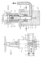
- Fig. 1 shows a shut-off device in the form of a gate valve.
- the housing 10 the actuating Spindle 12 and the shut-off body 14, which can be moved up and down by the actuating spindle, in the form of a closing wedge, which bears sealingly on the seat ring 16 when the shut-off element is closed.
- the shut-off body separates the inflow side 18 from the outflow side 20. These represent the connecting pieces for pipelines, of which a pipeline 22 is indicated.
- the housing 10 has a bulge 24 which limits the dead space 26 to the outside. On the outflow side or inflow side of the shut-off element, the dead space 26 is delimited by the circular cylindrical seat ring 16 and by the shut-off body 14.
- the additional valve 30 is arranged in the dead space 26. This arrangement is chosen so that the additional valve 30 is also closed in the closed position of the shut-off body.
- the additional valve 30 has a valve housing 38 in which a cylindrical shut-off piston 40 is vertically movable.
- the lower end of the shut-off piston 40 is designed in the shape of a circular cone and is aligned with the coaxially extending inlet channel 42.
- the shut-off piston 40 sits on a seat 44 which is formed at the upper end of the inlet channel.
- At the lower area of the piston chamber 46 there is an outlet channel which runs transversely to the shut-off piston axis and merges into the outlet line 36. This outlet line opens on the outflow side of the shut-off element, as can be seen from FIG. 1.
- a stuffing box 48 is provided, which engages around the shut-off piston and is arranged in an annular recess in the valve housing 38.
- a threaded ring 50 acting on it is provided for adjusting the fabric sleeve 48.
- other seals such as. B. 0-rings can also be used.
- a spring plate 52 is attached at the upper end of the shut-off piston 40, which protrudes from the housing 38. This has an upwardly angled edge 54 and an downwardly angled edge 56.
- a first helical spring 58 is guided from the lower edge 56 and is arranged between the spring plate 52 and the valve housing 38 or the threaded ring 50.
- a second coil spring 60 is also guided coaxially to the shut-off piston 40 from the upper edge 54 and is supported with its lower end on the spring plate 52.
- the upper end of the second coil spring 60 carries a plunger 62 guided by the upper edge 56, the vertical movement of which is limited by a union nut 64.
- the upper edge 66 of the tappet is in contact with the lower edge 32 of the shut-off body 14.
- the first coil spring 58 has a larger spring constant than the second coil spring 60.
- at least one horizontally running channel 68 can be provided, which connects the inlet channel 42 with the dead space horizontally.
- the inlet duct 42 or the duct 68 opens into the deepest region of the dead space 26.
- the shut-off element is arranged in a steam line, condensate can form in the interior 28 of the housing in the closed state, which accumulates at the lowest point, namely in the dead space 26, in the present installation of the shut-off element with a vertically running spindle.
- the penetration of steam into the interior 28 is possible because there is pressure equalization between the inflow side 18 and the interior 28, that is to say there is a construction-related connection, not shown in the drawing, from the inflow side 18 to the interior 28.
- the shut-off body 14 now moves upward during the opening process, the shut-off piston 40 is moved upward by the first helical spring 58, possibly with the cooperation of the pressure prevailing in the dead space.
- Fig. 3 the shut-off device is shown as a variant. While the interior of the shut-off element or the dead space is in permanent connection with the inflow side in the exemplary embodiment according to the FIG., These spaces are permanently connected with the outflow side in the present exemplary embodiment.
- the line 72 is provided, which, starting from the deepest area of the dead space, penetrates the seat ring 16 and opens into the outflow side.
- the additional valve 74 is also arranged below the closing body 14 and is actuated by its lower edge 32.
- the additional valve 74 is connected to the inflow side 18 via the pressure line 76, which likewise penetrates the seat ring 16.
- the line 72 must of course end at a distance from the wall of the bulge so that the liquid can enter.
- the structure of the additional valve including the assigned line 72 and its function can be better seen from the illustration in FIG. 4.
- the additional valve 74 here has a piston 78 on which has a rigidly and coaxially fastened piston rod 82 which protrudes from the cylinder 80 and is in contact with the lower edge 32 of the shut-off body 14.
- the pressure line 76 is connected, which connects the inflow side 18 to the cylinder space 84.
- An opening 86 to the dead space 16 is provided in the upper region of the cylinder 80.
- the length of the piston rod 82 and the overall design are selected such that in the closed position of the shut-off body 14 and when the piston rod 82 comes into contact with the lower edge 32, this opening 86 is blocked by the piston 78.
- 4 further shows the line 72 that is open at the ends, which leads from the deepest area of the dead space 26 to the outflow side 20 and opens there in the direction of the shut-off device flow.
- an additional valve according to the exemplary embodiment of FIGS. 5 and 6 is to be selected.
- the additional valve 88 is also present in the dead space 26 and is actuated by the lower edge 32 of the shut-off body 14.
- the actuation direction of the additional valve 88 is identical to the direction of movement of the shut-off body 14.
- the interior 28 and the dead space 26 are not connected to the inflow side and the outflow side in the closed position of the shut-off body 14.
- the auxiliary valve 88 is connected to the inflow side 18 via the pressure line 90 and to the outflow side 20 via the line 92.
- the internal structure of the additional valve 88 and the arrangement of these lines can be seen better from the illustration according to FIG. 6.
- the additional valve 88 has a cylinder 94 which guides a piston 96.
- a piston rod 98 projecting upward from the cylinder is centrally attached to this, the upper end of which is in contact with the lower edge 32 of the shut-off body 14.
- the lower region of the interior 100 is connected to the inflow side 18 by the pressure line 90.
- the outlet duct 102 leads to the interior 28 of the housing or to the dead space 26.
- This outlet channel is arranged in the wall of the cylinder Q4, it runs first in the horizontal and then in the vertical direction, so that its mouth is arranged on the upper edge of the cylinder 94.
- an outflow opening 104 is provided in the upper region of the interior 100. This is connected to the outflow side 20 of the shut-off element via the channel 106 incorporated in the cylinder wall and via the adjoining line 92.
- the opening 110 of a channel 112 leading to the deepest region of the dead space 16 is arranged. This channel 112 is also recessed in the wall of the cylinder 94. If necessary, a horizontal channel 113 can branch off from the lower end region of the channel 112 and lead to the dead space 26.
- the piston 96 has a recess 114 on its periphery, which connects the outlet opening 104 to the opening 110 when the piston is in the corresponding position. In this piston position, the outlet channel 102 is released at the same time.
- the piston 96 In the closed position of the shut-off body 14, the piston 96 is in the position shown in FIG. 6. In this case, the pressure on the inflow side 18 is loaded on the underside of the piston 96 up, that is from its closed position, the piston 96 is pressed upwards. In this upper position, the connection from the interior 100 to the outlet duct 102 is released and at the same time the connection between the duct 112 and the duct 106 is made through the space 114. A flow can now occur which leads from the inflow side 18, the line 90, the interior 100 and the outlet channel 102 to the dead space 16. A pressure builds up here, which presses the liquid accumulations indicated in FIG.
- the arrangement is such that the auxiliary valve 88 is fully open for the discharge of the liquid accumulation before the flow through the shut-off device is released or at least of a substantial release, there must be a sufficient differential pressure between the inflow side 18 and the outflow side 20 for the discharge of fluid accumulation.
- the piston In the closed position of the shut-off body 14, the piston is in the position shown in FIG. 6.
- any flow through the additional valve is prevented, and the interior 28 of the housing or the dead space 16 is separated both from the inflow side 18 and from the outflow side 20, because the piston 96 now closes the mouths of the channels 102, 106 and 112.
- FIG. 7 such a shut-off device which is installed with a horizontally running spindle 12.
- a dead space 116 is formed in the interior 28 of the housing, in which condensate can accumulate in the steam lines when the AbsDerrorgans is used.
- this collection is in a different place compared to FIGS. 1 to 6.
- the constructions according to FIGS. 1 to 6 can, however, easily be adapted to this case, in which the corresponding lines or connections are also led to the deepest area of the dead space, so that liquid accumulations can be removed completely.
- FIG. 7 Such a line 118 to the deepest area of the dead space is indicated in FIG. 7.
- the dead space can be at different locations depending on the installation position of the shut-off element. This is usually the deepest part of the interior. It is important here that the corresponding lines lead to the dead space, as is shown in the exemplary embodiment according to FIG. 7.
- An additional valve according to the invention can also be used in shut-off valves.
- the additional valve is to be arranged according to the example of FIGS. 1 to 7 and brought into operative connection with the valve disk for actuation.
- the passage cross-section of the additional valve and / or the lines or channels connected to it should only be so large that, when the additional valve is open, little or no pressure equalization occurs between the upstream and downstream sides. A substantial pressure equalization would adversely affect the formation of a flow through the bypass.
- the passage cross section of the bypass is - with the exception of the dead space - about a tenth to a fortieth, preferably one Twentieth to one thirtieth of the flow cross-section of the shut-off device.
Landscapes
- Engineering & Computer Science (AREA)
- General Engineering & Computer Science (AREA)
- Mechanical Engineering (AREA)
- Lift Valve (AREA)
- Sliding Valves (AREA)
Applications Claiming Priority (2)
| Application Number | Priority Date | Filing Date | Title |
|---|---|---|---|
| DE3221050 | 1982-06-04 | ||
| DE19823221050 DE3221050A1 (de) | 1982-06-04 | 1982-06-04 | Absperrorgan, insbesondere absperrschieber |
Publications (2)
| Publication Number | Publication Date |
|---|---|
| EP0096268A2 true EP0096268A2 (fr) | 1983-12-21 |
| EP0096268A3 EP0096268A3 (fr) | 1984-03-07 |
Family
ID=6165288
Family Applications (1)
| Application Number | Title | Priority Date | Filing Date |
|---|---|---|---|
| EP83105026A Withdrawn EP0096268A3 (fr) | 1982-06-04 | 1983-05-20 | Organe d'arrêt, en particulier vanne à tiroir |
Country Status (2)
| Country | Link |
|---|---|
| EP (1) | EP0096268A3 (fr) |
| DE (1) | DE3221050A1 (fr) |
Cited By (1)
| Publication number | Priority date | Publication date | Assignee | Title |
|---|---|---|---|---|
| CN102906474A (zh) * | 2010-05-27 | 2013-01-30 | 俄林·奥尔森 | 盲板阀的阀布置 |
Families Citing this family (3)
| Publication number | Priority date | Publication date | Assignee | Title |
|---|---|---|---|---|
| RU2259465C1 (ru) * | 2004-02-24 | 2005-08-27 | Закрытое акционерное общество "Нефтемашвнедрение" | Задвижка шиберно-штуцерная |
| ES2637216T3 (es) * | 2013-07-31 | 2017-10-11 | Rheavendors Services S.P.A. | Aparato para preparar bebidas |
| CN106870752B (zh) * | 2015-12-14 | 2019-05-07 | 中国石油天然气集团公司 | 一种具有限位机构的电动高温闸阀 |
Family Cites Families (4)
| Publication number | Priority date | Publication date | Assignee | Title |
|---|---|---|---|---|
| DE65701C (de) * | A. CLEPFIEN in Grabow a. O., Breitestrafse 8 | Dampfventil mit Dampfwasser-Ablafsvorrichtung | ||
| DE697931C (de) * | 1938-03-27 | 1940-10-28 | Julius Pulgrabia | Ventil, bei dem die Mittel fuer das Absperren des Dampfstromes und fuer das Abfuehren des Kondenswassers in einem Gehaeuse vereinigt sind |
| DE2423159C2 (de) * | 1974-05-10 | 1982-02-18 | Hans 8500 Nürnberg Kalb | Einrichtung zum Ableiten von Kondensat |
| US4041970A (en) * | 1976-06-09 | 1977-08-16 | Acf Industries, Incorporated | Quick bleed exhaust valve |
-
1982
- 1982-06-04 DE DE19823221050 patent/DE3221050A1/de not_active Withdrawn
-
1983
- 1983-05-20 EP EP83105026A patent/EP0096268A3/fr not_active Withdrawn
Cited By (1)
| Publication number | Priority date | Publication date | Assignee | Title |
|---|---|---|---|---|
| CN102906474A (zh) * | 2010-05-27 | 2013-01-30 | 俄林·奥尔森 | 盲板阀的阀布置 |
Also Published As
| Publication number | Publication date |
|---|---|
| DE3221050A1 (de) | 1983-12-08 |
| EP0096268A3 (fr) | 1984-03-07 |
Similar Documents
| Publication | Publication Date | Title |
|---|---|---|
| DE69410699T2 (de) | Ablagerungen verhinderndes Wasserventil | |
| DE69003344T2 (de) | Rückschlagventil. | |
| DE3642669A1 (de) | Eigenmediumgesteuertes, durch ein vorzugsweise elektromagnetisch betaetigtes steuerventil ausloesbares ventil | |
| DE2712062C2 (de) | Ventil | |
| DE2634175A1 (de) | Fluessigkeitsfuellstand-kontrollsystem | |
| DE3323324C2 (de) | Verfahren und Vorrichtung zum Steuern eines Rohrtrenners in Abhängigkeit einer an einer Vergleichsstelle vorgegebenen Druckdifferenz | |
| DE19722615A1 (de) | Leckagefrei schaltendes Doppelsitzventil | |
| DE2750833C2 (de) | Vorrichtung für Reinigungsflüssigkeits-Anschluß, Hubsicherung und Federwiderlager für Doppelsitz-Rohrleitungsschalter mit Leckkontrolle | |
| DE2253751A1 (de) | Ventilanordnung | |
| EP0112977A1 (fr) | Organe d'arrêt pour fluides agressifs | |
| DE2150852A1 (de) | Pumpsiphon | |
| DE1500191C3 (de) | Selbsttätige Tankfüll- und -entleerungsvorrichtung mit Haupt- und Hilfsventil | |
| DE3221050A1 (de) | Absperrorgan, insbesondere absperrschieber | |
| DE1750599B1 (de) | Gasflaschen-Absperrventil mit selbsttaetiger Hilfsabsperrvorrichtung | |
| DE69200415T2 (de) | Fernbedienbare Fülleinrichtung eines Ölbehälters. | |
| DE3610867A1 (de) | Verfahren und vorrichtung zum betreiben einer unterdruck-abwasseranlage | |
| EP0621066B1 (fr) | Installation de filtre de rinçage à contre-courant | |
| DE3509720C2 (fr) | ||
| WO2019020361A1 (fr) | Soupape à double siège ayant une membrane | |
| DE602004009491T2 (de) | Ausdehnungsgefäß mit Ventil | |
| DE3743842C2 (de) | Überflutungssicherung für Waschmaschinen | |
| DE3402441C2 (fr) | ||
| DE6920325U (de) | Abscheidevorrichtung zum abscheiden von fluessigkeiten und verunreinigungen aus einem druckgas | |
| DE102007017377B4 (de) | Hydrant-Entleerungssystem | |
| DE69128445T2 (de) | Automatisches ablaufventil |
Legal Events
| Date | Code | Title | Description |
|---|---|---|---|
| PUAI | Public reference made under article 153(3) epc to a published international application that has entered the european phase |
Free format text: ORIGINAL CODE: 0009012 |
|
| AK | Designated contracting states |
Designated state(s): AT BE CH FR LI NL |
|
| PUAL | Search report despatched |
Free format text: ORIGINAL CODE: 0009013 |
|
| AK | Designated contracting states |
Designated state(s): AT BE CH FR LI NL |
|
| STAA | Information on the status of an ep patent application or granted ep patent |
Free format text: STATUS: THE APPLICATION IS DEEMED TO BE WITHDRAWN |
|
| 18D | Application deemed to be withdrawn |
Effective date: 19841108 |
|
| RIN1 | Information on inventor provided before grant (corrected) |
Inventor name: WEIMER, PETER |