EP0096273A2 - Dispositif pour régler l'inclinaison entre le dossier et le siège d'un fauteuil transatlantique ou semblable - Google Patents
Dispositif pour régler l'inclinaison entre le dossier et le siège d'un fauteuil transatlantique ou semblable Download PDFInfo
- Publication number
- EP0096273A2 EP0096273A2 EP83105067A EP83105067A EP0096273A2 EP 0096273 A2 EP0096273 A2 EP 0096273A2 EP 83105067 A EP83105067 A EP 83105067A EP 83105067 A EP83105067 A EP 83105067A EP 0096273 A2 EP0096273 A2 EP 0096273A2
- Authority
- EP
- European Patent Office
- Prior art keywords
- seat
- fixed
- constraints
- chair
- supporting structure
- Prior art date
- Legal status (The legal status is an assumption and is not a legal conclusion. Google has not performed a legal analysis and makes no representation as to the accuracy of the status listed.)
- Withdrawn
Links
- 238000013519 translation Methods 0.000 claims abstract description 9
- 239000004744 fabric Substances 0.000 claims description 4
- 239000002184 metal Substances 0.000 claims description 3
- 229910000831 Steel Inorganic materials 0.000 claims description 2
- 239000010959 steel Substances 0.000 claims description 2
- 230000014616 translation Effects 0.000 description 6
- 230000000875 corresponding effect Effects 0.000 description 3
- 239000000463 material Substances 0.000 description 3
- 230000003014 reinforcing effect Effects 0.000 description 3
- 230000008878 coupling Effects 0.000 description 2
- 238000010168 coupling process Methods 0.000 description 2
- 238000005859 coupling reaction Methods 0.000 description 2
- 230000006866 deterioration Effects 0.000 description 1
Images

Classifications
-
- A—HUMAN NECESSITIES
- A47—FURNITURE; DOMESTIC ARTICLES OR APPLIANCES; COFFEE MILLS; SPICE MILLS; SUCTION CLEANERS IN GENERAL
- A47C—CHAIRS; SOFAS; BEDS
- A47C1/00—Chairs adapted for special purposes
- A47C1/02—Reclining or easy chairs
- A47C1/031—Reclining or easy chairs having coupled concurrently adjustable supporting parts
- A47C1/032—Reclining or easy chairs having coupled concurrently adjustable supporting parts the parts being movably-coupled seat and back-rest
- A47C1/03294—Reclining or easy chairs having coupled concurrently adjustable supporting parts the parts being movably-coupled seat and back-rest slidingly movable in the base frame, e.g. by rollers
-
- A—HUMAN NECESSITIES
- A47—FURNITURE; DOMESTIC ARTICLES OR APPLIANCES; COFFEE MILLS; SPICE MILLS; SUCTION CLEANERS IN GENERAL
- A47C—CHAIRS; SOFAS; BEDS
- A47C1/00—Chairs adapted for special purposes
- A47C1/02—Reclining or easy chairs
- A47C1/031—Reclining or easy chairs having coupled concurrently adjustable supporting parts
- A47C1/032—Reclining or easy chairs having coupled concurrently adjustable supporting parts the parts being movably-coupled seat and back-rest
-
- A—HUMAN NECESSITIES
- A47—FURNITURE; DOMESTIC ARTICLES OR APPLIANCES; COFFEE MILLS; SPICE MILLS; SUCTION CLEANERS IN GENERAL
- A47C—CHAIRS; SOFAS; BEDS
- A47C1/00—Chairs adapted for special purposes
- A47C1/02—Reclining or easy chairs
- A47C1/031—Reclining or easy chairs having coupled concurrently adjustable supporting parts
- A47C1/032—Reclining or easy chairs having coupled concurrently adjustable supporting parts the parts being movably-coupled seat and back-rest
- A47C1/033—Reclining or easy chairs having coupled concurrently adjustable supporting parts the parts being movably-coupled seat and back-rest the coupling member being a flexible strip
Definitions
- the present invention concerns a device for adjusting and fixing the back and the seat of an arm-chair, deck-chair or the like to a supporting structure of same, allowing the seat and back to reach numberless positions of reciprocal inclination between two end inclinations.
- a lot of arm-chairs, deck-chairs or similar are known in which the back and the seat can reach different positions of reciprocal inclination thanks to indented adjusting devices provided with a series of notches, each one correspon ding to a determined inclination between the seat and back.
- Said adjusting devices have the drawback of allowing a limited number of inclinations between the seat the back, moreover considerably spaced.
- the back in fact, is hinged in correspondence to the connecting point with the seat and the change in inclination between back and seat is obtained by causing the back to rotate around said hinges, the rotations involving translation along an arc of circumference of the user's barycenter, which is approximately where his loins are.
- An object of the present invention is to provide an arm-chair, deck-chair or the like, in which the inclination between back and seat is adjustable, without solutions of continuity, between two end inclinations corresponding to a minimum and a maximum value respectively, allowing moreover the user to reach said inclinations without changing his barycenter and therefore with a very reduced effort, generally without the need of removing his bust from the chair back.
- a device for adjusting and fixing the back and the seat of an arm-chair, deck-chair or the like to a supporting structure of same, allowing the seat and back to reach different positions of reciprocal inclination between two end inclinations respectively corresponding to a minimum and maximum inclination characterized in that said back is supported and fixed in a rotary way around an horizontal axis fixed with respect to the supporting structure; in that said seat is fixed to the back by means of hinges and to the structure by means of constraints which support the seat and allow it to perform predetermined of translation and/or rotation movements compatible with the presence of said hinges and without solutions of continuity between said end inclinations, and in that at least one of said contraints is braked.
- the change of inclination between the seat and back is obtained by causing the back to rotate around An axis placed approximately where the user's barycenter is, so that his bust rotates around said barycenter, which substantially remains steady.
- the ends of the back move along arcs of circumference and the seat, which is hinged at the back lower end, performs movements of translation and rotation around an ideal axis.
- the possibility for the seat of longitudinally translating with respect to the supporting structure is given by a constraint obtained by coupling in a sliding way a sleeve and a longitudinal guide, while its rotary movement is obtained thanks to a suitable arc-of-circumference configuration of said guide or allowing the sleeve to rotate around a given axis.
- the back and the seat slide through numberless relative positions, each of them being steady thanks to the correct distribution of weights and to a braking action exercised by the constraints themselves.
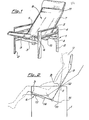
- the illustrated arm-chair is of the type consisting of a metal framework and in which the supporting surface is constituted by a piece of cloth or other material kept stretched thanks to the framework itself.
- Said arm-chair comprises a supporting structure 1 consisting of two elements 2 having a turned-up-U shape, fixed to one another by shaped crossbars 3 and equipped with reinforcing horizontal bars 4.
- a metal tubular framework 7 is fixed to the supporting structure 1 by means of constraints 5 and 6; said framework is formed by an upper section 8 and a lower section 9, respectively forming the back and the seat of the arm-chair, said sections being fixed to one another by means of hinges 10.
- a shaped cloth 11 constituting the supporting surface of the arm-chair is fixed to the framework 7.
- the constraints 5 connecting the back 8 to-the supporting structure 1 are hinges allowing the back to rotate around a fixed horizontal axis 12 (fig. 2).
- the constraints 6 connecting the seat 9 to the supporting structure 1 are small guiding blocks 13, for example hinged to the supporting structure 1 itself, sliding along longitudinal guides ' 14, for istance fixed to the seat 9.
- Said constraints 6 allow the seat 9 to perform movements of translation and rotation, in that, as illustrated in fig. 2, when the back 8 rotates around its own axis 12, its ends move along arcs of circumference 15 and the seat 9, thanks to the contraints consisting of hinges 10, follows said movements performing rotations and translations.
- the rotation axis 12 of the back 8 is substantially placed in correspondence to the barycenter B of the user U and the bust of the latter rotates around the axis 12 and actually around his own barycenter B.
- the user U by simply winning the work of friction of the contraints 5, 6 and 10, can vary at will and without solution of continuity the reciprocal inclination of back and seat, passing throungh numberless positions of balance, while his own barycenter B remains substantially unchanged. Said positions of balance are kept and secured thanks to the braking action exercised by the friction forces inside the constraints, for instance by the coupling of small blocks 13 and longitudinal guides 14.
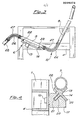
- Figs. 3 and 4 illustrate a first embodiment of the constraints 6 connecting the seat 9 to the supporting structure 1.
- Each of said constraints 6 comprises a small block 13 hinged by means of a pivot 18 to the reinforcing bar 4 and a rectilinear and longitudinal guide 14 fixed on the seat 9 side.
- the guide 14 has an X section, the upper gap 19 of which houses a tube of the framework 7 and the lower ends 20 of which are coupled to a seat 21 provided in the small block, so that the guide cannot leave the small block. Stop devices, for instance consisting of screws 22 fixing the guides 14 to tube 7, define the end positions of seat 9 with respect to the supporting structure.
- Both the small block 13 and guide 1 4 are suitably made of plastic material.
- Figures 5 and 6 illustrate a second embodiment of the constraints 6 connecting the seat 9 to the supporting structure 1, in which the translations and rotations of the seat take place along longitudinal guides 23, having an arc-of circumference shape, fixed to the seat itself and fixed in a sliding way to the reinforcing bars 4 by means of small blocks 24.
- Each small block 24 is provided with a horizontal notch 25 in which a flattend section of the guide 23 slides.
- the guides 23 and/or the small blocks 24 can be made of plastic material.
- Figures 3 and 5 illustrate two different constraints 10 connecting the back 8 and seat 9.
- said constraint is formed by hinges of a conventional type, known in itself, while in fig. 3 it is constituted by sleeves 26 of molded rubber, the ends of which are partly inserted into the tubes constituting the frame of the back 8 and seat 9.
- Each sleeve 26 houses a small steel cable 27, the ends of which are fixed, for example by rivetting, to the tubes constituting the back and the seat.
- Said sleeve 26 allows the back and seat to reciprocally rotate around an axis external to the sleeve itself, in such a way that a rotation-axis inside the supporting framework does not form. This prevents the deterioration of the cloth constituting the supporting surface of the chair, in that there is not a single rotation line thereon.
- Other sleeves 26 can be used to fix a feet-rest element 28 to the framework forming the seat 9 (fig. 3), said sleeves allowing the user to vary the reciprocal inclination between the seat and the feet-rest element.
Landscapes
- Health & Medical Sciences (AREA)
- Dentistry (AREA)
- General Health & Medical Sciences (AREA)
- Chairs For Special Purposes, Such As Reclining Chairs (AREA)
Applications Claiming Priority (2)
| Application Number | Priority Date | Filing Date | Title |
|---|---|---|---|
| IT2169482 | 1982-06-04 | ||
| IT21694/82A IT1151580B (it) | 1982-06-04 | 1982-06-04 | Dispositivo di regolazione della inclinazione reciproca fra lo schienale ed il sedile di una poltrona, sdraio o simile |
Publications (2)
| Publication Number | Publication Date |
|---|---|
| EP0096273A2 true EP0096273A2 (fr) | 1983-12-21 |
| EP0096273A3 EP0096273A3 (fr) | 1984-12-27 |
Family
ID=11185506
Family Applications (1)
| Application Number | Title | Priority Date | Filing Date |
|---|---|---|---|
| EP83105067A Withdrawn EP0096273A3 (fr) | 1982-06-04 | 1983-05-21 | Dispositif pour régler l'inclinaison entre le dossier et le siège d'un fauteuil transatlantique ou semblable |
Country Status (2)
| Country | Link |
|---|---|
| EP (1) | EP0096273A3 (fr) |
| IT (1) | IT1151580B (fr) |
Cited By (7)
| Publication number | Priority date | Publication date | Assignee | Title |
|---|---|---|---|---|
| US4984846A (en) * | 1987-10-19 | 1991-01-15 | J. E. Ekornes A/S | Arrangement in an adjustable chair |
| AU630296B1 (en) * | 1991-05-22 | 1992-10-22 | I-Shan Chang | An adjustable rotation chair |
| US5314237A (en) * | 1992-02-12 | 1994-05-24 | Kimball International Marketing, Inc. | Reclining chair |
| USD707995S1 (en) | 2012-05-23 | 2014-07-01 | Hni Technologies Inc. | Chair |
| US9198514B2 (en) | 2012-05-23 | 2015-12-01 | Hni Technologies Inc. | Chair with pivot function and method of making |
| WO2019167027A1 (fr) * | 2018-03-01 | 2019-09-06 | Nabile Lalaoua | Mécanisme d'assise coulissant, pivotant et inclinable pour chaise et banc |
| US20220378208A1 (en) * | 2019-06-17 | 2022-12-01 | Quali Co., Ltd. | Tilt chair |
Family Cites Families (3)
| Publication number | Priority date | Publication date | Assignee | Title |
|---|---|---|---|---|
| AT147449B (de) * | 1935-04-17 | 1936-10-26 | Josef Teltscher | Sitz- oder Liegemöbel mit schwenkbarer Lehne und einem mit dieser verbundenen, verschiebbareu Sitz. |
| US3536358A (en) * | 1968-12-11 | 1970-10-27 | Peter F Masucci | Slideable seat construction |
| BE799878A (fr) * | 1973-01-24 | 1973-09-17 | Lusch Ferdinand | Chaise longue reglable |
-
1982
- 1982-06-04 IT IT21694/82A patent/IT1151580B/it active
-
1983
- 1983-05-21 EP EP83105067A patent/EP0096273A3/fr not_active Withdrawn
Cited By (10)
| Publication number | Priority date | Publication date | Assignee | Title |
|---|---|---|---|---|
| US4984846A (en) * | 1987-10-19 | 1991-01-15 | J. E. Ekornes A/S | Arrangement in an adjustable chair |
| AU630296B1 (en) * | 1991-05-22 | 1992-10-22 | I-Shan Chang | An adjustable rotation chair |
| US5314237A (en) * | 1992-02-12 | 1994-05-24 | Kimball International Marketing, Inc. | Reclining chair |
| USD707995S1 (en) | 2012-05-23 | 2014-07-01 | Hni Technologies Inc. | Chair |
| US9198514B2 (en) | 2012-05-23 | 2015-12-01 | Hni Technologies Inc. | Chair with pivot function and method of making |
| US9743773B2 (en) | 2012-05-23 | 2017-08-29 | Hni Technologies, Inc. | Method of making a chair with pivot function |
| US10448742B2 (en) | 2012-05-23 | 2019-10-22 | Hni Technologies Inc. | Chair with pivot function |
| WO2019167027A1 (fr) * | 2018-03-01 | 2019-09-06 | Nabile Lalaoua | Mécanisme d'assise coulissant, pivotant et inclinable pour chaise et banc |
| US20220378208A1 (en) * | 2019-06-17 | 2022-12-01 | Quali Co., Ltd. | Tilt chair |
| US12089741B2 (en) * | 2019-06-17 | 2024-09-17 | Quali Co., Ltd. | Tiltable chair |
Also Published As
| Publication number | Publication date |
|---|---|
| IT8221694A0 (it) | 1982-06-04 |
| EP0096273A3 (fr) | 1984-12-27 |
| IT1151580B (it) | 1986-12-24 |
Similar Documents
| Publication | Publication Date | Title |
|---|---|---|
| US5114212A (en) | Chair with adjustable arm rest | |
| KR900008873B1 (ko) | 다목적 운동기구 및 그의 저항조립체 | |
| US3586322A (en) | Combined rowing apparatus and exercising apparatus | |
| EP0096273A2 (fr) | Dispositif pour régler l'inclinaison entre le dossier et le siège d'un fauteuil transatlantique ou semblable | |
| US7276018B2 (en) | Reclining exercise chair | |
| KR100596475B1 (ko) | 단일 액추에이터 4방향 척추 위치 지정 장치 | |
| US6004248A (en) | Exercise apparatus | |
| CN107257701B (zh) | 包含用于执行俯卧曲腿练习的移动支撑件的曲腿练习机器 | |
| EP0494736A2 (fr) | Voiture d'enfant pliable et mécanisme de pliage utilisé là-dedans | |
| US20070037674A1 (en) | Multi-exercise apparatus | |
| US4182511A (en) | Exerciser device | |
| WO2004011100A1 (fr) | Appareil de culture physique a poulie coulissante | |
| ITMI20071317A1 (it) | Macchina per esercizi ginnici. | |
| US4602780A (en) | Multipurpose exercise apparatus | |
| US11413494B1 (en) | Push pull rower | |
| US2433548A (en) | Exerciser | |
| US3761081A (en) | Exercising device | |
| EP1057430A1 (fr) | Chaise avec siège basculant | |
| JPH01155850A (ja) | 機能回復用トレーニング装置 | |
| US2928675A (en) | Therapeutic apparatus | |
| EP0480327A1 (fr) | Essoreuse à balai | |
| ITBO980170A1 (it) | Macchina per l'esercizio muscolare. | |
| US2406344A (en) | Exercising machine | |
| EP0086913A1 (fr) | Appareil d'exercices à poulies | |
| ES2253249T3 (es) | Aparato de musculacion para hacer "bombas". |
Legal Events
| Date | Code | Title | Description |
|---|---|---|---|
| PUAI | Public reference made under article 153(3) epc to a published international application that has entered the european phase |
Free format text: ORIGINAL CODE: 0009012 |
|
| AK | Designated contracting states |
Designated state(s): AT BE CH DE FR GB LI NL SE |
|
| PUAL | Search report despatched |
Free format text: ORIGINAL CODE: 0009013 |
|
| AK | Designated contracting states |
Designated state(s): AT BE CH DE FR GB LI NL SE |
|
| STAA | Information on the status of an ep patent application or granted ep patent |
Free format text: STATUS: THE APPLICATION IS DEEMED TO BE WITHDRAWN |
|
| 18D | Application deemed to be withdrawn |
Effective date: 19850828 |
|
| RIN1 | Information on inventor provided before grant (corrected) |
Inventor name: BISCARINI, ALDO |