EP0096329A2 - Dispositif de support et de contrôle pour voiles - Google Patents
Dispositif de support et de contrôle pour voiles Download PDFInfo
- Publication number
- EP0096329A2 EP0096329A2 EP83105332A EP83105332A EP0096329A2 EP 0096329 A2 EP0096329 A2 EP 0096329A2 EP 83105332 A EP83105332 A EP 83105332A EP 83105332 A EP83105332 A EP 83105332A EP 0096329 A2 EP0096329 A2 EP 0096329A2
- Authority
- EP
- European Patent Office
- Prior art keywords
- boom
- support
- mast
- cylinders
- ship
- Prior art date
- Legal status (The legal status is an assumption and is not a legal conclusion. Google has not performed a legal analysis and makes no representation as to the accuracy of the status listed.)
- Withdrawn
Links
Images




Classifications
-
- B—PERFORMING OPERATIONS; TRANSPORTING
- B63—SHIPS OR OTHER WATERBORNE VESSELS; RELATED EQUIPMENT
- B63H—MARINE PROPULSION OR STEERING
- B63H9/00—Marine propulsion provided directly by wind power
- B63H9/04—Marine propulsion provided directly by wind power using sails or like wind-catching surfaces
- B63H9/08—Connections of sails to masts, spars, or the like
- B63H9/10—Running rigging, e.g. reefing equipment
-
- B—PERFORMING OPERATIONS; TRANSPORTING
- B63—SHIPS OR OTHER WATERBORNE VESSELS; RELATED EQUIPMENT
- B63B—SHIPS OR OTHER WATERBORNE VESSELS; EQUIPMENT FOR SHIPPING
- B63B15/00—Superstructures, deckhouses, wheelhouses or the like; Arrangements or adaptations of masts or spars, e.g. bowsprits
- B63B15/0083—Masts for sailing ships or boats
-
- B—PERFORMING OPERATIONS; TRANSPORTING
- B63—SHIPS OR OTHER WATERBORNE VESSELS; RELATED EQUIPMENT
- B63H—MARINE PROPULSION OR STEERING
- B63H9/00—Marine propulsion provided directly by wind power
- B63H9/04—Marine propulsion provided directly by wind power using sails or like wind-catching surfaces
- B63H9/08—Connections of sails to masts, spars, or the like
- B63H9/10—Running rigging, e.g. reefing equipment
- B63H9/1078—Boom brakes
Definitions
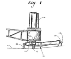
- a sail support assembly comprising a support frame 10 mounted on the deck 12 of a vessel, a boom support 14 rotatably mounted on the frame 10, and a mast 16 rotatably mounted within the boom support 14.
- the sail support assembly is similar in some respects to that shown in co-pending application serial 290, 234 filed-August 5, 1981, in that the boom is mounted in cantilever fashion onto support 14 so that the boom can resist the downward force of its own weight and the upward force of the sail without supporting lines.
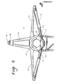
- the support frame 10 comprises laterally extending portions 22 and 24 and a forwardly extending portion 26:
- the frame 10 is secured to the main deck 12 by pylons 28 and 30 disposed at the outer ends of the laterally extending portions, a trunnion 32 at the rear of the frame, and a pin 34 extending forwardly from the portion 26 into an aperture 36 in an upwardly projecting retaining member 38 fastened to the deck 12.
- the frame mounting allows a slight amount of fore and aft movement to allow the measurement of the forward propulsion force applied to the ship by the sail.
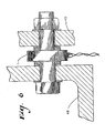
- a load cell L is mounted between a plate 40 fastened to the deck and a plate 42 fastened to the support frame, so that any forward movement of the frame resulting from forces applied thereto by the mast results in deformation of the load cell.
- Load cells for this purpose are well known in the art, and provide a changing electrical parameter with changing load, which information can be transmitted to a remote location such as the ships bridge.
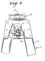
- a pair of hydraulic cylinders Cl and C2 are provided on the support frame, with the rod ends Rl and R2 thereof being connected to radially extending mounting ears 44 and 46 on the boom support, and the head ends of the cylinders being connected to the laterally extending portions 22 and 24 at the outer ends thereof.
- the cylinders are so oriented in-relation to the boom support that they are capable of rotating the boom support through approximately 90 0 in either direction from the centerline of the ship without interference between the rods Rl and R2 and the boom support.
- the cylinders are also so oriented in relation to the boom support that when the boom is on the centerline of the ship, each cylinder is partially extended and the angle between the radius (the line between the rod connection to the boom support and the center of rotation of the boom support) and the axis of the rod is between the dead center position of 1 8 0 0 and the maximum torque position of 90 0 .
- the exact angle will depend on the length and stroke of the cylinders, and in a typical case will be between about 120 and 150 0 .
- the cylinders also must be so oriented that when one cylinder rod is in the dead center (180 0 ) position the other cylinder rod is substantially at 90 o to the radius to provide the maximum torque.
- the operation of the cylinders is controlled by the hydraulic system illustrated in Figure 8.
- the cylinders must not only be able to swing the boom to any position up to about 90° to port or starboard, they must also be able to hold the boom in a desired position, and must be able to limit the speed at which the boom swings, such as when the boom is swung out to catch a favorable wind.
- the hydraulic control circuit comprises a source of fluid pressure P, which is fed to a master control valve V1 which has left, center, and right positions.
- the valve V1 is normally in the center position and may be moved to the left or right position manually or by other means to cause the boom to swing to port or starboard respectively. Swinging of the boom occurs so long as the valve Vl is held in the left or right position (within the limits of travel of the boom), and stops when the valve VI is released to return to the center position.
- valve Vl When valve Vl is shifted to the right, fluid flows through the valve VI to valves V2 and V3 which are cam actuated in a manner to appear hereinafter.
- the valves V2 and V3 and the cylinders Cl and C2 are in a position which corresponds to the fore and aft position of the boom, and in such position when valve Vl is shifted to the right valve V2 admits pressure through supply line Ll and check valve Kl to the head end of cylinder Cl, and valve V3 admits pressure through supply line L2 and check valve K2 to the rod end of cylinder C2.
- shifting valve Vl to the right causes the boom to swing to starboard, and as can be seen from the diagram of Figure 8, shifting valve Vl to the left will cause the boom to swing to port.
- the motion control valves limit the angular rate at which the boom can swing in the following manner.
- the wind pressure on the sail may be great enough that the resulting rotating force applied by the sail to the boom support tends to force the pistons of the cylinders to move faster than the boom support, would be moved by the fluid supply from the pump P.
- the rotating force applied by the sail therefore tends to cause a reduction in pressure in the head end of cylinder Cl and at the rod end of cylinder C2.
- the motion control valves are normally spring-biased to the closed position and are opened by pressure on a pilot line connected between the valve and a source of pressure,'with the amount of opening being a function of the amount of pressure.
- the pilot line P4 of valve V4 is connected to the fluid supply line Ll feeding the head end of cylinder Cl
- the pilot line P5 of valve V5 is connected to the fluid supply line L2 feeding the rod end of cylinder C2.
- the reduction of pressure on the supply lines Ll and L2 causes a corresponding reduction of pressure on the pilot lines P4 and P5 of valves V4 and V5 respectively, to allow said valves to move toward the closed position to thereby reduce the rate of flow of fluid cut of the cylinders and thereby limit the rate at which the boom can swing.
- cam 48 on the boom support 14 operates a microswitch Sl, which actuates a solenoid Ql of valve V3 to shift it to the left so that the flow of fluid to cylinder C2 is reversed, and pressure is applied to the head end thereof.
- the rotating force applied thereto comes only from cylinder Cl, however the arrangement of the cylinders is such that in this position cylinder Cl is-acting substantially perpendicular to the radius, so that it can apply maximum torque to the boom support.
- the force applied by cylinder C2 increases as the force applied by cylinder Cl decreases due to the decreasing radius.
- valve VI To thereafter swing the boom inwardly (counter-clockwise) valve VI is shifted to the left, so that fluid pressure is supplied to the rod end of cylinder Cl and to the rod end of cylinder C2 until the resulting clockwise rotation of the boom support causes cylinder C2 to again reach the dead center position, where the cam 48 actuates switch Sl to .cause valve V3 to move back to its original position to thereby reverse the fluid flow to cylinder C2.
- valve V1 When valve V1 is in the center position, the head and rod ends of both cylinders are connected to the return line to the supply tank T, so that there is no pressure on pilot lines P4, P5, P6, P7 of the motion control valves.
- the motion control valves are therefore closed, and, in conjunction with the check valves in the supply lines, prevent fluid from discharging from either end of the cylinders.
- the hydraulic system allows the boom support to swing in a direction to reduce the force.
- This is accomplished by lines R4, R5, R6, and R7 which connect the cylinder ends to a relief inlet of the associated motion control valve.
- An excessive pressure at the relief inlet caused by an excessive pressure in one end of the associated cylinder causes the valve to open to reduce the pressure, and thereby allowing movement of the cylinder rod and the boom.
- FIG. 9 there is illustrated a graph showing the torque applied to the boom at various boom angles. As shown in the graph, the maximum torque of either cylinder occurs when the other cylinder is on dead center with no available torque. The graph also shows that the cylinder arrangement provides maximum total torque when the boom is on the centerline of the ship.
- hydraulic cylinders are utilized to rotate the boom support, it will be understood that in some applications pneumatic cylinders or mechanical linear actuators may be used, provided that mechanical braking means is provided for retaining the boom in the desired orientation.
Landscapes
- Engineering & Computer Science (AREA)
- Combustion & Propulsion (AREA)
- Ocean & Marine Engineering (AREA)
- Mechanical Engineering (AREA)
- Chemical & Material Sciences (AREA)
- Sustainable Energy (AREA)
- Life Sciences & Earth Sciences (AREA)
- Sustainable Development (AREA)
- Jib Cranes (AREA)
- Insulation, Fastening Of Motor, Generator Windings (AREA)
- Iron Core Of Rotating Electric Machines (AREA)
- Fluid-Pressure Circuits (AREA)
- Steering Controls (AREA)
Applications Claiming Priority (2)
| Application Number | Priority Date | Filing Date | Title |
|---|---|---|---|
| US38472382A | 1982-06-03 | 1982-06-03 | |
| US384723 | 1989-07-24 |
Publications (2)
| Publication Number | Publication Date |
|---|---|
| EP0096329A2 true EP0096329A2 (fr) | 1983-12-21 |
| EP0096329A3 EP0096329A3 (fr) | 1985-05-15 |
Family
ID=23518487
Family Applications (1)
| Application Number | Title | Priority Date | Filing Date |
|---|---|---|---|
| EP83105332A Withdrawn EP0096329A3 (fr) | 1982-06-03 | 1983-05-30 | Dispositif de support et de contrôle pour voiles |
Country Status (4)
| Country | Link |
|---|---|
| EP (1) | EP0096329A3 (fr) |
| JP (1) | JPS5957093A (fr) |
| FI (1) | FI831969L (fr) |
| NO (1) | NO831982L (fr) |
Cited By (5)
| Publication number | Priority date | Publication date | Assignee | Title |
|---|---|---|---|---|
| EP0926063A3 (fr) * | 1997-12-18 | 2001-08-08 | Harald Sima | Accessoire de bateau |
| US6732670B2 (en) | 2000-06-13 | 2004-05-11 | William Richards Rayner | Sailing craft |
| EP1607323A1 (fr) * | 2004-06-15 | 2005-12-21 | Harken Italy S.P.A. | Système pneumatique pour utiliser l'accastillage de pont d'un voilier |
| ES2433484R1 (es) * | 2011-05-30 | 2014-02-12 | Eduardo RODRIGUEZ VILA | Sistema control de velocidad/paso de la botavara |
| EP4461633A1 (fr) * | 2023-05-12 | 2024-11-13 | AlfaWall Oceanbird AB | Système de propulsion éolienne et navire |
Family Cites Families (5)
| Publication number | Priority date | Publication date | Assignee | Title |
|---|---|---|---|---|
| DE1175572B (de) * | 1963-01-23 | 1964-08-06 | Atlas Werke Ag | Ladegeschirr fuer Schiffe |
| AU474863B2 (en) * | 1970-09-03 | 1973-03-08 | Proline Manufacturing Pty. Ltd | Swivelling device for rotating platforms cranes andthe like |
| AU502182B2 (en) * | 1975-03-17 | 1979-07-19 | Massey-Ferguson Inc | Hydraulic swing mechanism |
| JPS57198194A (en) * | 1981-05-28 | 1982-12-04 | Nippon Kokan Kk <Nkk> | Furling and unfurling system for marine canvas |
| US4499841A (en) * | 1981-08-05 | 1985-02-19 | Lloyd Bergeson | Sail rigging and control system |
-
1983
- 1983-05-30 EP EP83105332A patent/EP0096329A3/fr not_active Withdrawn
- 1983-06-01 FI FI831969A patent/FI831969L/fi not_active Application Discontinuation
- 1983-06-02 NO NO831982A patent/NO831982L/no unknown
- 1983-06-03 JP JP58099296A patent/JPS5957093A/ja active Pending
Cited By (8)
| Publication number | Priority date | Publication date | Assignee | Title |
|---|---|---|---|---|
| EP0926063A3 (fr) * | 1997-12-18 | 2001-08-08 | Harald Sima | Accessoire de bateau |
| US6732670B2 (en) | 2000-06-13 | 2004-05-11 | William Richards Rayner | Sailing craft |
| EP1607323A1 (fr) * | 2004-06-15 | 2005-12-21 | Harken Italy S.P.A. | Système pneumatique pour utiliser l'accastillage de pont d'un voilier |
| AU2005202594B2 (en) * | 2004-06-15 | 2011-03-10 | Harken Italy S.P.A. | Drive system for activating/deactivating motion transmission in sailing boats |
| AU2005202594B8 (en) * | 2004-06-15 | 2011-07-07 | Harken Italy S.P.A. | Drive system for activating/deactivating motion transmission in sailing boats |
| ES2433484R1 (es) * | 2011-05-30 | 2014-02-12 | Eduardo RODRIGUEZ VILA | Sistema control de velocidad/paso de la botavara |
| EP4461633A1 (fr) * | 2023-05-12 | 2024-11-13 | AlfaWall Oceanbird AB | Système de propulsion éolienne et navire |
| WO2024235723A1 (fr) * | 2023-05-12 | 2024-11-21 | Alfawall Oceanbird Ab | Système de propulsion éolienne et navire |
Also Published As
| Publication number | Publication date |
|---|---|
| FI831969A0 (fi) | 1983-06-01 |
| EP0096329A3 (fr) | 1985-05-15 |
| FI831969A7 (fi) | 1983-12-04 |
| NO831982L (no) | 1983-12-05 |
| JPS5957093A (ja) | 1984-04-02 |
| FI831969L (fi) | 1983-12-04 |
Similar Documents
| Publication | Publication Date | Title |
|---|---|---|
| US3722455A (en) | Hydraulic power trim and power tilt system for a marine propulsion device | |
| US3903827A (en) | Non-heeling hull assembly | |
| CA1165185A (fr) | Gouvernail de bateau | |
| US4307677A (en) | Rudder for aquatic craft and floating apparatus | |
| US4673358A (en) | Mounting arrangement for outboard drive | |
| EP0284014A1 (fr) | Système de construction pour l'inclinaison du mât d'un bateau à voile vers le côté au vent | |
| NO149308B (no) | Fremgangsmaate for desoksygenering av vann | |
| US4342275A (en) | Fin rudder for ships | |
| US4773882A (en) | Hydraulic steering assembly for outboard engines | |
| KR20030025232A (ko) | 풍력추진식 선박 | |
| US3768426A (en) | Sailboat rigging | |
| US3828683A (en) | Marine load transfer system | |
| US3116710A (en) | Apparatus for controllably varying the elevation and angle of thrust of outboard moto propellers | |
| GB2096553A (en) | Hydraulic system for marine propulsion device with sequentially operating tilt and trim means | |
| CA1214690A (fr) | Systeme hydraulique de relevage et d'orientation en sequence pour moteur de bateau | |
| US3380424A (en) | Vessel arresting apparatus | |
| JPS5957093A (ja) | 帆支持装置 | |
| US3640238A (en) | Means for drawing together and aligning the separable parts of composite load-carrying vessels or watercraft | |
| US4499841A (en) | Sail rigging and control system | |
| SU1625779A1 (ru) | Судно | |
| JPS6044197B2 (ja) | 船舶用平型伝動装置 | |
| US4944239A (en) | Flap rudder and steering system | |
| US5562508A (en) | Marine propulsion arrangement | |
| US5782195A (en) | Braking/reversing rudder for marine vessel | |
| CA1262215A (fr) | Systeme de gouverne a volet actif |
Legal Events
| Date | Code | Title | Description |
|---|---|---|---|
| PUAI | Public reference made under article 153(3) epc to a published international application that has entered the european phase |
Free format text: ORIGINAL CODE: 0009012 |
|
| AK | Designated contracting states |
Designated state(s): BE DE FR GB IT NL SE |
|
| PUAL | Search report despatched |
Free format text: ORIGINAL CODE: 0009013 |
|
| AK | Designated contracting states |
Designated state(s): BE DE FR GB IT NL SE |
|
| STAA | Information on the status of an ep patent application or granted ep patent |
Free format text: STATUS: THE APPLICATION IS DEEMED TO BE WITHDRAWN |
|
| 18D | Application deemed to be withdrawn |
Effective date: 19860116 |
|
| RIN1 | Information on inventor provided before grant (corrected) |
Inventor name: BATES, ALEXANDER P., JR. Inventor name: GLUCKSMAN, MAURICE A. |