EP0096366B1 - Dispositif de dérivation de charges électrostatiques pour robinet à boisseau sphérique - Google Patents
Dispositif de dérivation de charges électrostatiques pour robinet à boisseau sphérique Download PDFInfo
- Publication number
- EP0096366B1 EP0096366B1 EP83105457A EP83105457A EP0096366B1 EP 0096366 B1 EP0096366 B1 EP 0096366B1 EP 83105457 A EP83105457 A EP 83105457A EP 83105457 A EP83105457 A EP 83105457A EP 0096366 B1 EP0096366 B1 EP 0096366B1
- Authority
- EP
- European Patent Office
- Prior art keywords
- ball
- spring
- spindle
- contact
- bushing
- Prior art date
- Legal status (The legal status is an assumption and is not a legal conclusion. Google has not performed a legal analysis and makes no representation as to the accuracy of the status listed.)
- Expired
Links
- 239000002184 metal Substances 0.000 claims description 17
- 239000012530 fluid Substances 0.000 claims 2
- 238000012423 maintenance Methods 0.000 description 5
- 229910001220 stainless steel Inorganic materials 0.000 description 2
- 239000010935 stainless steel Substances 0.000 description 2
- 239000000126 substance Substances 0.000 description 2
- 239000011248 coating agent Substances 0.000 description 1
- 238000000576 coating method Methods 0.000 description 1
- 238000009795 derivation Methods 0.000 description 1
- 238000004880 explosion Methods 0.000 description 1
- 239000002360 explosive Substances 0.000 description 1
- LFULEKSKNZEWOE-UHFFFAOYSA-N propanil Chemical compound CCC(=O)NC1=CC=C(Cl)C(Cl)=C1 LFULEKSKNZEWOE-UHFFFAOYSA-N 0.000 description 1
- 238000007789 sealing Methods 0.000 description 1
Images
Classifications
-
- H—ELECTRICITY
- H05—ELECTRIC TECHNIQUES NOT OTHERWISE PROVIDED FOR
- H05F—STATIC ELECTRICITY; NATURALLY-OCCURRING ELECTRICITY
- H05F3/00—Carrying-off electrostatic charges
- H05F3/02—Carrying-off electrostatic charges by means of earthing connections
Definitions
- the invention relates to a device for electrostatic discharge in ball valves by means of a contact element between a valve ball and a spindle and a second contact element between the spindle and a stuffing box or nut.
- the ball must be grounded via the spindle in ball valves used in the chemical industry. This is necessary because the ball can become electrostatically charged and explosions can occur when using explosive or other dangerous media.
- the slip rings used lose tension very quickly, so that a lifting, even if only very slight, from the spindle is detected. Even during maintenance work on the housing of the ball valves, the contact spring can be damaged unnoticed, so that its functionality is restricted.
- the object of the invention is to provide inexpensive devices for electrostatic discharge in a ball valve of the type mentioned, which are no longer exposed to external influences and influences of the media used.
- the devices must be easy to install and protected from damage during maintenance work.
- the contact pins used are about 90% cheaper than the usual spring arrangements. The reason for this is that the contact pins for the watch industry are manufactured in very large numbers. These are used as holding pins for bracelets on wristwatches.
- the contact pins are very easy to use and are used between the ball and the spindle. It is no longer necessary to carry easily damaged parts with you during maintenance work, just the insensitive pins.
- the spring Due to the coating of the pens, the spring is no longer exposed to the often very aggressive media found in the chemical industry. Even during maintenance work, damage to the contact pins can no longer occur.
- the pins as well as the sleeves can be made of stainless steel and are therefore ideal when using aggressive media. It has also been shown that the time required for attaching the contact pins is considerably less than when using the previously customary contact arrangements. In addition to the advantage of the lower purchase price, there is also time savings during assembly.
- the sprung ball is also a part that is found very often in industry and is therefore available on the market at very low cost. It has been found to be advantageous that the sleeve has a thread on the outside for screwing into the part surrounding the spindle. A slot for engaging a screwdriver is made in the end of the sleeve opposite the contact ball.
- the sleeve can be made of stainless steel.
- the pin mentioned above can also be attached. Due to the electrostatic dissipation by means of two metal pins or a metal pin and a spring-loaded ball, the solution to the underlying is thus in both cases in the ball valve according to the invention Task reliably guaranteed.
- the embodiment working with a pin and a ball ensures smooth operation and reliable wear-free operation while maintaining reliable contact.
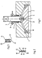
- the housing 1 of the ball valve there is a round opening in the middle on the upper side.
- a spindle 3 which is surrounded by a stuffing box or nut 4, passes through this opening.
- the ball has a square recess in the upper part, in which a pin 21 engages. This pin is at the lower end of the spindle. A hole is provided in this pin which receives the contact pin 5.
- the contact pin consists of a sleeve 14, preferably made of metal, two metal pins 12, 13 and a spring 15.
- the sleeve has an inwardly directed flanged edge 18, 19 on both sides.
- a spring is arranged between the two metal pins and tends to push the two metal pins away from one another.
- the two metal pins each have a shoulder 16, 17 at their inner ends. Thus, the two metal pins cannot be pressed out of the sleeve by the spring force.
- the spindle 3 is surrounded by a stuffing box or nut 4. This stuffing box or nut is firmly connected to the housing. As a result, the spindle is firmly guided in the opening of the housing.
- a bore is provided in the stuffing box or nut which has a thread and has the same diameter as the bore which receives the contact pin 5. This bore in the stuffing box or nut receives the sprung ball 6.
- the spring-loaded ball 6 is seated in a sleeve 21, preferably made of metal, which is closed at one end and has an opening at the other end, which has an inwardly directed flanged edge 22.
- a sleeve 21 preferably made of metal, which is closed at one end and has an opening at the other end, which has an inwardly directed flanged edge 22.
- the spring 23 being supported at one end against the closed sleeve, with the other end pushing the ball 20 outwards.
- the ball 20 has a larger diameter than the opening formed by the flange 22. Thus, the ball 20 cannot be pressed out of the sleeve 21 by the spring force.
- a pin as shown in FIG. 2 can also be used between the spindle and the stuffing box or nut.
Landscapes
- Taps Or Cocks (AREA)
Claims (7)
caractérisé en ce que
au moins l'élément de contact (5) entre la bille (2) et la broche (3) consiste en deux pointes métalliques (12,13) qui sont guidées dans une douille (14) et qui sont pressées au moyen d'un ressort (15) disposé entre les deux pointes métalliques contre la bille (2) et la broche (3) de sorte que le ressort n'est pas exposé à des fluides aggressifs.
caractérisé en ce que
le deuxième élément de contact (6) consiste en deux pointes métalliques (12,13) qui sont guidées dans und douille (14) et qui sont pressées vers l'extérieur par un ressort (15) disposé entre les deux pointes métalliques de sorte que le ressort n'est pas exposé à des fluides aggressifs.
caractérisé en ce que
les deux pointes métalliques (12, 13) présentent chacune à leur extrémité intérieure un épaulement (16, 17) et sont tenues dans la douille (14) par un collet rabattu vers l'intérieur (18, 19) se trouvant aux deux extrémités de la douille (14).
caractérisé en ce que
le deuxième élément de contact (6) se trouvant dans la douille ou l'écrou presse-étoupe (4) consiste en une bille de contact (20) qui est guidée dans une douille (21) et est pressée vers l'extérieur par un ressort (23).
caractérisé en ce que
la bille de contact (20) possède un diamètre supérieur à l'ouverture de la douille (21) formée par un collet rabattu (22) par lequel la bille de contact (20) est tenue dans la douille (21).
caractérisé en ce que
la douille (14) pour le guidage des pointes de métal est en métal.
caractérisé en ce que
la douille (21) pour le guidage de la bille de contact est en métal.
Priority Applications (1)
| Application Number | Priority Date | Filing Date | Title |
|---|---|---|---|
| AT83105457T ATE32010T1 (de) | 1982-06-04 | 1983-06-01 | Vorrichtung zur elektrostatischen ableitung bei kugelhaehnen. |
Applications Claiming Priority (4)
| Application Number | Priority Date | Filing Date | Title |
|---|---|---|---|
| DE3221258 | 1982-06-04 | ||
| DE19823221258 DE3221258C1 (de) | 1982-06-04 | 1982-06-04 | Kugelhahn mit Vorrichtungen zur elektrostatischen Ableitung zum geerdeten Gehäuse |
| DE8311255U | 1983-04-15 | ||
| DE8311255 | 1983-04-15 |
Publications (3)
| Publication Number | Publication Date |
|---|---|
| EP0096366A2 EP0096366A2 (fr) | 1983-12-21 |
| EP0096366A3 EP0096366A3 (en) | 1985-06-12 |
| EP0096366B1 true EP0096366B1 (fr) | 1988-01-13 |
Family
ID=25802271
Family Applications (1)
| Application Number | Title | Priority Date | Filing Date |
|---|---|---|---|
| EP83105457A Expired EP0096366B1 (fr) | 1982-06-04 | 1983-06-01 | Dispositif de dérivation de charges électrostatiques pour robinet à boisseau sphérique |
Country Status (2)
| Country | Link |
|---|---|
| EP (1) | EP0096366B1 (fr) |
| DE (1) | DE3375354D1 (fr) |
Families Citing this family (6)
| Publication number | Priority date | Publication date | Assignee | Title |
|---|---|---|---|---|
| FR2636513A1 (fr) * | 1988-09-20 | 1990-03-23 | Maurel Jacques | Pietement antistatique de siege de bureau |
| ITBO20020358A1 (it) * | 2002-06-07 | 2003-12-09 | Magneti Marelli Powertrain Spa | Valvola a farfalla per un motore a combustione interna con dissipatore di cariche elettrostatiche e relativo attuatore |
| CN103307303A (zh) * | 2013-07-01 | 2013-09-18 | 自贡信赖泵阀制造有限公司 | 三位清管型三通球阀 |
| DE102017119205A1 (de) | 2017-08-22 | 2019-02-28 | Samson Ag | Stellventil |
| DE202017105035U1 (de) | 2017-08-22 | 2018-11-23 | Samson Ag | Stellventil |
| DE202018105866U1 (de) | 2018-10-12 | 2018-11-15 | Samson Ag | Ventil |
Family Cites Families (3)
| Publication number | Priority date | Publication date | Assignee | Title |
|---|---|---|---|---|
| FR545514A (fr) * | 1921-10-20 | 1922-10-13 | Prise de courant électrique à rotule | |
| GB381354A (en) * | 1931-10-26 | 1932-10-06 | Macintosh Cable Company Ltd | An improved electrical joint, coupling or connection |
| FR2398241A1 (fr) * | 1977-07-21 | 1979-02-16 | Gachot Jean | Robinet a boule de securite |
-
1983
- 1983-06-01 DE DE8383105457T patent/DE3375354D1/de not_active Expired
- 1983-06-01 EP EP83105457A patent/EP0096366B1/fr not_active Expired
Also Published As
| Publication number | Publication date |
|---|---|
| EP0096366A3 (en) | 1985-06-12 |
| DE3375354D1 (en) | 1988-02-18 |
| EP0096366A2 (fr) | 1983-12-21 |
Similar Documents
| Publication | Publication Date | Title |
|---|---|---|
| EP0528204B1 (fr) | Boîtier à moyens de serrage | |
| EP0173115A2 (fr) | Electrovanne pour application à vide | |
| DE102013106595A1 (de) | Öffnungs- und Schließventil | |
| EP0096366B1 (fr) | Dispositif de dérivation de charges électrostatiques pour robinet à boisseau sphérique | |
| EP0192051A2 (fr) | Dispositif de rangement pour feuilles perforées | |
| DE112008001364T5 (de) | Verbinder für Fluiddruckvorrichtungen | |
| DE69001870T2 (de) | Ventilflanschhaltesystem. | |
| DD202065A5 (de) | Vorrichtung zur befestigung eines deckels auf einem gehaeuse, insbesondere auf einem schiebergehaeuse | |
| DE3221258C1 (de) | Kugelhahn mit Vorrichtungen zur elektrostatischen Ableitung zum geerdeten Gehäuse | |
| EP0086995B1 (fr) | Plaque de base, en particulier pour fixations de skis | |
| DE1400767A1 (de) | Sicherungsvorrichtung mit federnder,gewoelbter Sicherungsscheibe | |
| DE901612C (de) | Sicherung fuer den Zusammenbau eines Absperrschiebers | |
| DE8311255U1 (de) | Vorrichtung zur elektrostatischen ableitung bei kugelhaehnen zum geerdeten gehaeuse | |
| DE3907815C2 (fr) | ||
| DE7907144U1 (de) | Ventil, insbesondere sicherheitsventil fuer schmieranlagen | |
| DE2203800B2 (de) | Klemmvorrichtung für ein Drahtseil, eine Stange oder ein anderes lasttragendes GUed | |
| DE574916C (de) | Rueckstellvorrichtung fuer auf einer gemeinsamen Achse lose gelagerte Anzeigerklappen | |
| DE1298797B (de) | Absperrventil | |
| DE8216355U1 (de) | Kugelbahn | |
| DE659744C (de) | Verschlusseinrichtung fuer Schmiernippel | |
| EP3021017A1 (fr) | Soupape de securite | |
| DE1252006B (fr) | ||
| DE3048749C2 (fr) | ||
| DE1149213B (de) | Vorrichtung an Haehnen zur Fixierung des Kuekens in seinem Sitz | |
| EP0379952B1 (fr) | Embouchure pour conduits à gaz |
Legal Events
| Date | Code | Title | Description |
|---|---|---|---|
| PUAI | Public reference made under article 153(3) epc to a published international application that has entered the european phase |
Free format text: ORIGINAL CODE: 0009012 |
|
| AK | Designated contracting states |
Designated state(s): AT BE CH DE FR GB IT LI LU NL SE |
|
| 17P | Request for examination filed |
Effective date: 19840125 |
|
| RIN1 | Information on inventor provided before grant (corrected) |
Inventor name: BRAIG, HANS |
|
| PUAL | Search report despatched |
Free format text: ORIGINAL CODE: 0009013 |
|
| RAP1 | Party data changed (applicant data changed or rights of an application transferred) |
Owner name: CHEMAT GMBH ARMATUREN FUER INDUSTRIE- UND NUKLEARA |
|
| AK | Designated contracting states |
Designated state(s): AT BE CH DE FR GB IT LI LU NL SE |
|
| 17Q | First examination report despatched |
Effective date: 19861104 |
|
| GRAA | (expected) grant |
Free format text: ORIGINAL CODE: 0009210 |
|
| AK | Designated contracting states |
Kind code of ref document: B1 Designated state(s): AT BE CH DE FR GB IT LI LU NL SE |
|
| PG25 | Lapsed in a contracting state [announced via postgrant information from national office to epo] |
Ref country code: NL Effective date: 19880113 Ref country code: IT Free format text: LAPSE BECAUSE OF FAILURE TO SUBMIT A TRANSLATION OF THE DESCRIPTION OR TO PAY THE FEE WITHIN THE PRESCRIBED TIME-LIMIT;WARNING: LAPSES OF ITALIAN PATENTS WITH EFFECTIVE DATE BEFORE 2007 MAY HAVE OCCURRED AT ANY TIME BEFORE 2007. THE CORRECT EFFECTIVE DATE MAY BE DIFFERENT FROM THE ONE RECORDED. Effective date: 19880113 Ref country code: BE Effective date: 19880113 |
|
| REF | Corresponds to: |
Ref document number: 32010 Country of ref document: AT Date of ref document: 19880115 Kind code of ref document: T |
|
| PG25 | Lapsed in a contracting state [announced via postgrant information from national office to epo] |
Ref country code: SE Effective date: 19880131 |
|
| REF | Corresponds to: |
Ref document number: 3375354 Country of ref document: DE Date of ref document: 19880218 |
|
| ET | Fr: translation filed | ||
| PG25 | Lapsed in a contracting state [announced via postgrant information from national office to epo] |
Ref country code: AT Effective date: 19880601 |
|
| NLV1 | Nl: lapsed or annulled due to failure to fulfill the requirements of art. 29p and 29m of the patents act | ||
| PG25 | Lapsed in a contracting state [announced via postgrant information from national office to epo] |
Ref country code: LU Free format text: LAPSE BECAUSE OF NON-PAYMENT OF DUE FEES Effective date: 19880630 Ref country code: LI Effective date: 19880630 Ref country code: CH Effective date: 19880630 |
|
| GBV | Gb: ep patent (uk) treated as always having been void in accordance with gb section 77(7)/1977 [no translation filed] | ||
| PLBE | No opposition filed within time limit |
Free format text: ORIGINAL CODE: 0009261 |
|
| STAA | Information on the status of an ep patent application or granted ep patent |
Free format text: STATUS: NO OPPOSITION FILED WITHIN TIME LIMIT |
|
| PG25 | Lapsed in a contracting state [announced via postgrant information from national office to epo] |
Ref country code: GB Free format text: LAPSE BECAUSE OF NON-PAYMENT OF DUE FEES Effective date: 19881122 |
|
| 26N | No opposition filed | ||
| REG | Reference to a national code |
Ref country code: CH Ref legal event code: PL |
|
| PGFP | Annual fee paid to national office [announced via postgrant information from national office to epo] |
Ref country code: FR Payment date: 19900613 Year of fee payment: 8 |
|
| PGFP | Annual fee paid to national office [announced via postgrant information from national office to epo] |
Ref country code: DE Payment date: 19900621 Year of fee payment: 8 |
|
| PG25 | Lapsed in a contracting state [announced via postgrant information from national office to epo] |
Ref country code: FR Effective date: 19920228 |
|
| PG25 | Lapsed in a contracting state [announced via postgrant information from national office to epo] |
Ref country code: DE Effective date: 19920401 |