EP0096380A2 - Procédé de détection d'objets ferromagnétiques souterrains - Google Patents
Procédé de détection d'objets ferromagnétiques souterrains Download PDFInfo
- Publication number
- EP0096380A2 EP0096380A2 EP83105485A EP83105485A EP0096380A2 EP 0096380 A2 EP0096380 A2 EP 0096380A2 EP 83105485 A EP83105485 A EP 83105485A EP 83105485 A EP83105485 A EP 83105485A EP 0096380 A2 EP0096380 A2 EP 0096380A2
- Authority
- EP
- European Patent Office
- Prior art keywords
- ferromagnetic
- ferromagnetic body
- magnetic field
- body according
- earth
- Prior art date
- Legal status (The legal status is an assumption and is not a legal conclusion. Google has not performed a legal analysis and makes no representation as to the accuracy of the status listed.)
- Withdrawn
Links
Images

Classifications
-
- G—PHYSICS
- G01—MEASURING; TESTING
- G01V—GEOPHYSICS; GRAVITATIONAL MEASUREMENTS; DETECTING MASSES OR OBJECTS; TAGS
- G01V3/00—Electric or magnetic prospecting or detecting; Measuring magnetic field characteristics of the earth, e.g. declination, deviation
- G01V3/08—Electric or magnetic prospecting or detecting; Measuring magnetic field characteristics of the earth, e.g. declination, deviation operating with magnetic or electric fields produced or modified by objects or geological structures or by detecting devices
- G01V3/087—Electric or magnetic prospecting or detecting; Measuring magnetic field characteristics of the earth, e.g. declination, deviation operating with magnetic or electric fields produced or modified by objects or geological structures or by detecting devices the earth magnetic field being modified by the objects or geological structures
Definitions
- the invention relates to a method for locating underground, ferromagnetic bodies, e.g. Sliding caps. Push rods or marking rods.
- the sensitivity of the device can be changed by changing the distance between the two probes.
- the two magnetic field probes are compensated against each other so that the normal earth magnetic field is not displayed, however, any disturbance of this field or the presence of other magnetic, so-called secondary fields. This means that other metals are not registered by this device. be treated.
- the new method described here is a passive method in which no frequencies are emitted and can therefore also be used in areas where high-frequency generators are undesirable.
- a simple one-button operation enables handling by untrained personnel.
- Fig. 1 shows that the depth (1) with the proposed method with respect to different rod lengths (2) of slide rods (3, 3a, 3b, 3c, 3d) is very large. Herewith it is therefore possible to detect deeply buried underground ferromagnetic bodies in a very sensitive manner using the proposed method.
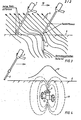
- Fig. 3 shows the disturbance of the magnetic field lines (4) below the earth's surface (6) when a marking rod (5) made of a ferromagnetic material is buried there.
- the marking rod (5) there is a bundle (9) of the magnetic field lines (4) which is detected by the magnetometer (7) guided along the surface of the earth (6).
- the magnetometer (7) consists of two highly sensitive magnetic field probes (8, 8,) which are housed in two tubes that can be pushed into each other. When the inhomogeneity (bundling 9) of the magnetic field lines (4) is detected, a different voltage is induced in one magnetic field probe (8) than in the other magnetic field probe.
- the electrical bridge circuit is out of balance because the two magnetic field probes (Hall probes) are interconnected in an electrical bridge circuit with respect to the bridge diagonals. A voltage will therefore appear in the bridge diagonal across several successive amplifiers. highly amplified and then finally displayed optically or acoustically in the magnetometer (7).
- the magnetometer (7) is guided in the direction of the arrow (10) along the earth's surface (6).
- Fig. 4 shows the maximum inhomogeneity in the form of a distribution curve (12) above the earth's surface (6).
- a slide housing (13) is buried underground, the slide rod (3) of which in particular contributes to the concentration of the earth's magnetic field.
- the field lines (11) then run in the direction shown and generate the distribution curve (12) of the inhomogeneity shown schematically above.
- the magnetometer (7) guided over the slide housing (13) will therefore detect the maximum of the inhomogeneity with its magnetic field probes (8, 8) and the location of the slide housing (13) has thus been found.
- the new method can be used particularly as a marking system.
- Marking probes with a length of 60 cm can still be safely located to a depth of 80 cm. This makes it possible to mark position positions with marking sticks, which can be introduced far below the plow depth.
- the marking stick which is driven into the ground, consists of a surface-protected steel in a T-shape. This shape is almost torsion-free and, thanks to its special shape, prevents it from drifting when the probe is driven in.
- This marking system is much cheaper than previously known systems, e.g. the introduction of a resonant circuit at the marking point, this resonant circuit being located using a resonance meter.
- a rod-shaped magnetic tag carrier is particularly useful.
Landscapes
- Life Sciences & Earth Sciences (AREA)
- Engineering & Computer Science (AREA)
- Remote Sensing (AREA)
- Environmental & Geological Engineering (AREA)
- Geology (AREA)
- Physics & Mathematics (AREA)
- Geochemistry & Mineralogy (AREA)
- Electromagnetism (AREA)
- General Life Sciences & Earth Sciences (AREA)
- General Physics & Mathematics (AREA)
- Geophysics (AREA)
- Geophysics And Detection Of Objects (AREA)
Applications Claiming Priority (2)
| Application Number | Priority Date | Filing Date | Title |
|---|---|---|---|
| DE19823221301 DE3221301A1 (de) | 1982-06-05 | 1982-06-05 | Verfahren zum orten unterirdisch, ferromagnetischer koerper |
| DE3221301 | 1982-06-05 |
Publications (2)
| Publication Number | Publication Date |
|---|---|
| EP0096380A2 true EP0096380A2 (fr) | 1983-12-21 |
| EP0096380A3 EP0096380A3 (fr) | 1984-09-05 |
Family
ID=6165438
Family Applications (1)
| Application Number | Title | Priority Date | Filing Date |
|---|---|---|---|
| EP83105485A Withdrawn EP0096380A3 (fr) | 1982-06-05 | 1983-06-03 | Procédé de détection d'objets ferromagnétiques souterrains |
Country Status (2)
| Country | Link |
|---|---|
| EP (1) | EP0096380A3 (fr) |
| DE (1) | DE3221301A1 (fr) |
Cited By (2)
| Publication number | Priority date | Publication date | Assignee | Title |
|---|---|---|---|---|
| EP0125741A3 (en) * | 1983-01-20 | 1986-06-25 | Scopemoor Limited | Detector for buried objects |
| EP0216070A1 (fr) * | 1985-07-25 | 1987-04-01 | Numec Instruments Inc. | Instrument pour la détection des corps ferromagnétiques |
Families Citing this family (2)
| Publication number | Priority date | Publication date | Assignee | Title |
|---|---|---|---|---|
| DE3922303A1 (de) * | 1989-07-07 | 1991-01-10 | Vallon Gmbh | Magnetometer zum orten von im erdreich befindlichen magnetischen gegenstaenden |
| DE19641196C2 (de) * | 1996-09-24 | 1998-07-09 | Andreas Dr Fischer | Verfahren und Vorrichtung zum Detektieren von Objekten im Boden |
Family Cites Families (6)
| Publication number | Priority date | Publication date | Assignee | Title |
|---|---|---|---|---|
| DE1448360A1 (de) * | 1964-06-09 | 1969-03-27 | Erich Pfanstiel | Verfahren und Geraet zum Ermitteln eines im Erdreich verdeckten Gegenstandes,insbesondere einer Grenzmarkierung od.dgl. |
| US3961245A (en) * | 1974-11-20 | 1976-06-01 | Schonstedt Instrument Company | Magnetic locator having improved sensors |
| US4066962A (en) * | 1976-12-08 | 1978-01-03 | The Singer Company | Metal detecting device with magnetically influenced Hall effect sensor |
| DE2832251A1 (de) * | 1978-07-22 | 1980-02-21 | Foerster Friedrich Dr | Verfahren und anordnung zum aufsuchen ferromagnetischer koerper |
| FR2441183A1 (fr) * | 1978-11-09 | 1980-06-06 | Semplanor | Grillage de signalisation des dispositifs enterres |
| DE3122643A1 (de) * | 1981-06-06 | 1983-01-05 | REDAR Nah- Ortungstechnik GmbH, 6100 Darmstadt | "anordnung zur markierung und ortung von molchen in rohrleitungssystemen, insbesondere pipelines" |
-
1982
- 1982-06-05 DE DE19823221301 patent/DE3221301A1/de not_active Withdrawn
-
1983
- 1983-06-03 EP EP83105485A patent/EP0096380A3/fr not_active Withdrawn
Cited By (3)
| Publication number | Priority date | Publication date | Assignee | Title |
|---|---|---|---|---|
| EP0125741A3 (en) * | 1983-01-20 | 1986-06-25 | Scopemoor Limited | Detector for buried objects |
| US4719426A (en) * | 1983-01-20 | 1988-01-12 | Scopemoor Limited | Method for magnetically detecting a localized disturbance of the ground |
| EP0216070A1 (fr) * | 1985-07-25 | 1987-04-01 | Numec Instruments Inc. | Instrument pour la détection des corps ferromagnétiques |
Also Published As
| Publication number | Publication date |
|---|---|
| EP0096380A3 (fr) | 1984-09-05 |
| DE3221301A1 (de) | 1983-12-08 |
Similar Documents
| Publication | Publication Date | Title |
|---|---|---|
| DE69429319T2 (de) | Offene magnetische Struktur | |
| Garland | Combined analysis of gravity and magnetic anomalies | |
| DE69018294T2 (de) | Gerät zur Richtungs- und Positionsbestimmung eines unterirdischen Leiters. | |
| DE3619308C1 (de) | Sonde fuer ein Metallsuchgeraet | |
| DE4022739A1 (de) | Vorrichtung zur pruefung von mit magnetischen eigenschaften ausgestatteten messobjekten | |
| DE112009002497T5 (de) | Magnetresonanzverfahren unter Verwendung einer phasenmodulierten Impulsfolge mit einem konstanten kleinen Anregungswinkel | |
| EP0096380A2 (fr) | Procédé de détection d'objets ferromagnétiques souterrains | |
| EP0436675A1 (fr) | Procede et dispositif de localisation de sous-marins. | |
| DE3317787C2 (fr) | ||
| DE3028410A1 (de) | Messverfahren fuer die hysteresekurve von magnetischen werkstoffen | |
| DE2552397C1 (de) | Anordnung von einer oder mehreren Magnetometer-Sonden | |
| Gay Jr | The effects of cathodically protected pipelines on aeromagnetic surveys | |
| DE69001534T2 (de) | Verfahren und Anlage zur Detektierung von Umkehrungen des erdmagnetischen Feldes durch Messungen in einem Bohrloch. | |
| DE950390C (de) | Verfahren und Einrichtungen zur Bestimmung der magnetischen Eigenschaften von magnetischem Material | |
| DE69007120T2 (de) | Verfahren zur detektion und dimensionierung von fehlern in netzförmigen metallischen strukturen. | |
| DE4105842A1 (de) | Verfahren zur lokalisierung von muffen in unterirdisch verlegten ferromagnetischen rohrleitungen | |
| DE102016113136B4 (de) | Verfahren zur Charakterisierung eines metallischen Störkörpers | |
| DE19510114A1 (de) | Einrichtung zum Messen magnetischer Remanenz | |
| DE10300168A1 (de) | Integrierte multiple mehrdimensionale geophysikalische Sende- und Empfangsantennenspule | |
| AT231002B (de) | Verfahren und Vorrichtung zur Bestimmung von geringen remanenten magnetischen Momenten schwach magnetischer Proben | |
| DE10030191C2 (de) | Vorrichtung und Verfahren zur Ortung und zur Bestimmung der Ausdehnung von nicht sichtbaren Körpern aus ferromagnetischen Materialien in nichtferromagnetischer Umgebung | |
| DE509285C (de) | Verfahren zur Bestimmung der Streichrichtung und des Neigungssinnes von durch ein erstes Sondier-Bohrloch getroffenen Gesteinsschichten | |
| DE102006034471B4 (de) | Vorrichtung zur Erzeugung eines gradierten homogenen Magnetfelds | |
| DE552090C (de) | Verfahren zur Bestimmung des Fallsinnes von Sedimentschichten | |
| DE3844652C2 (en) | Measurement probe with small magnetometer |
Legal Events
| Date | Code | Title | Description |
|---|---|---|---|
| PUAI | Public reference made under article 153(3) epc to a published international application that has entered the european phase |
Free format text: ORIGINAL CODE: 0009012 |
|
| AK | Designated contracting states |
Designated state(s): AT BE CH DE FR GB LI SE |
|
| PUAL | Search report despatched |
Free format text: ORIGINAL CODE: 0009013 |
|
| 17P | Request for examination filed |
Effective date: 19840605 |
|
| AK | Designated contracting states |
Designated state(s): AT BE CH DE FR GB LI SE |
|
| 17Q | First examination report despatched |
Effective date: 19860314 |
|
| STAA | Information on the status of an ep patent application or granted ep patent |
Free format text: STATUS: THE APPLICATION IS DEEMED TO BE WITHDRAWN |
|
| 18D | Application deemed to be withdrawn |
Effective date: 19860725 |
|
| RIN1 | Information on inventor provided before grant (corrected) |
Inventor name: PFAFF, HELMUT Inventor name: JAECKLE, EUGEN, ING. GRAD. |