EP0096405A1 - Système de chargement et déchargement de disque - Google Patents
Système de chargement et déchargement de disque Download PDFInfo
- Publication number
- EP0096405A1 EP0096405A1 EP83105544A EP83105544A EP0096405A1 EP 0096405 A1 EP0096405 A1 EP 0096405A1 EP 83105544 A EP83105544 A EP 83105544A EP 83105544 A EP83105544 A EP 83105544A EP 0096405 A1 EP0096405 A1 EP 0096405A1
- Authority
- EP
- European Patent Office
- Prior art keywords
- disk
- holding section
- loading
- unloading system
- push
- Prior art date
- Legal status (The legal status is an assumption and is not a legal conclusion. Google has not performed a legal analysis and makes no representation as to the accuracy of the status listed.)
- Granted
Links
Images




Classifications
-
- G—PHYSICS
- G11—INFORMATION STORAGE
- G11B—INFORMATION STORAGE BASED ON RELATIVE MOVEMENT BETWEEN RECORD CARRIER AND TRANSDUCER
- G11B17/00—Guiding record carriers not specifically of filamentary or web form, or of supports therefor
- G11B17/02—Details
- G11B17/04—Feeding or guiding single record carrier to or from transducer unit
- G11B17/05—Feeding or guiding single record carrier to or from transducer unit specially adapted for discs not contained within cartridges
- G11B17/053—Indirect insertion, i.e. with external loading means
- G11B17/054—Indirect insertion, i.e. with external loading means with pivoting loading means
-
- G—PHYSICS
- G11—INFORMATION STORAGE
- G11B—INFORMATION STORAGE BASED ON RELATIVE MOVEMENT BETWEEN RECORD CARRIER AND TRANSDUCER
- G11B17/00—Guiding record carriers not specifically of filamentary or web form, or of supports therefor
- G11B17/02—Details
- G11B17/022—Positioning or locking of single discs
- G11B17/028—Positioning or locking of single discs of discs rotating during transducing operation
- G11B17/032—Positioning by moving the door or the cover
Definitions
- This invention relates to disk loading and unloading systems, and more particularly is concerned. with a disk loading and unloading system suitable for use with digital audio disk players, analog players, etc.
- This invention has as its object the providing of a disk loading and unloading system enabling a disk to be mounted in a player and removed therefrom with the operator merely touching a peripheral edge of the disk, without the hand being brought into direct contact with surfaces of the disk on which information is stored.
- the disk loading and unloading system comprises a disk holding section which is pivotally movable with respect to a main body of the system.
- a disk inserted in the disk holding section moves upwardly to an upper position in which the disk is partly out of the disk holding section, so that the disk can be removed therefrom by holding same at its outer peripheral edge.
- the disk is preferably moved upwardly so that a portion of the disk from the outer periphery thereof substantially to the vicinity of a center opening thereof clears the disk holding section to be exposed to view.
- - To move the disk upwardly to the aforesaid upper position effectively, -.
- Fig. 1 is a front view showing a player for playing a compact digital audio disk of 12 cm in diameter, comprising a front panel 1 formed of synthetic resinous material or metal by die casting which covers the front of the player and has some decorative value, a series of knobs 2 for operating the player, a knob 3 for turning on and off a power source, indicating sections 4 for indicating the operating condition of the player, a disk loading and unloading section 5 and a disk-6 loaded in the player and placed in a playing position.
- Fig. 2 is a front view, with certain parts being shown in section, of the disk loading mechanism of the disk player shown in Fig. 1, showing the internal structure by removing the loading blind;
- Fig. 3 is a rear view of the disk loading mechanism shown in Fig. 2;
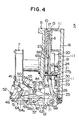
- Fig. 4 is a left side view, with certain parts being shown in section, of the disk loading mechanism shown in Fig. 2;
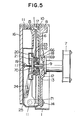
- Fig. 5 is a vertical sectional view of the disk securing section located in a central portion in Fig. 2;
- Fig. 6 is a side view, with certain parts being shown in section, of the drive motor system showing the disk holder in an open position.
- a main motor 7 for driving the disk 6 to rotate is secured to a central portion of a unit plate 8 produced by die casting.
- the unit plate 8 has attached thereto for movement in a transverse direction a pickup (not shown), which is movable radially of the disk 6 and emanates a laser beam to read information stored in the disk 6.
- the main motor 7 includes a main shaft 9 having secured thereto a turntable 69 having a magnet 18 secured to a surface thereof facing the disk 6.
- the main shaft 9 has a center spindle 70 secured to its forward end.
- a disk guide 13 is fitted between the center spindle 70 and the turntable 69 for sliding movement axially of the main shaft 9 and normally urged by the biasing force of a spring 12 surrounding the main shaft 9 of the disk guide 13 and the turntable 69 to move toward the center spindle 70.
- the disk guide 13 is provided with an inclined portion at an outer periphery thereof, which is in contact with a center opening formed on the disk 6, to thereby secure the disk 6 in place and position same at its center.
- a back plate 10 formed of synthetic resinous material is formed with a guide opening 66 for receiving the turntable 69 therein.
- the guide opening 66 is rectangular in shape and has a transverse dimention greater than the radius of the disk 6 to allow the pickup to move in a transverse direction to read the information stored in the disk 6.
- the back plate 10 is located in spaced juxtaposed relation to a disk holder 11 with a transparent clear guide 15 formed of. synthetic resinous material and allowing the disk 6 to be viewed being interposed therebetween.
- the back plate 10 and the disk holder 11 are clamped together by screws at four corners to support therein a mechanism for moving the disk 6 in a vertical direction.
- the disk holder 11 has projections 6'8 formed integrally therewith at lower portions of left and right sides thereof.
- the projections 68 are each inserted in a bearing opening formed at one leg of an L-shaped metal fitting 71 which is screwed at the other leg to the back surface of the unit plate 8 as indicated at 14 as shown in Fig. 7.
- a loading blind 16 which is transparent to allow the disk 6 to be viewed through the clear guide 15 is located in the front of the disk holder 11.
- the loading blind 16 is screwed to the back plate 10 at four corners and provided with a decorative design.
- a slot 17 for inserting the disk 6 therethrough is defined between the back plate 10 and the clear guide 15 at the tops thereof.
- a clamp holder 20 is attached to a guide shaft 19 secured to the disk holder 11 for sliding movement leftwardly and rightwardly in the figure.
- the clamp . holder 20 has secured thereto on a side thereof facing the disk 6 a magnet 21 which is of the same polarity as an opposed magnet 22, so that the magnets 21 and 22 repel each other.
- Fitted on an inner side of the clamp holder 20 is a disk clamper 23 which is fitted at its central portion to the center spindle 70.
- the magnet 22 is secured in a position on the disk clamper 23 opposite the magnet 21.
- the magnets 21 and 22 repel each other but the magnets 18 and 22 attract each other becuase they are of opposite polarities, to secure the disk 6 in place and rotate same together with the disk holder 11 as the latter is rotated by the motor 7.
- the clamp holder 20 has projections 20a on left and right sides thereof and each projection 20a is received in an opening formed at one end of one of clamp arms 24.
- Each of the clamp arms 24 has at the other end thereof a projection inserted in a bearing 25 which is mounted on the disk holder 11, so that the arms 24 will move in pivotal movement as the clamp holder 20 moves back and forth.
- a wire spring 26 is wound around each projection of clamp arm 24 so that the clamp arms 24 are urged by the biasing forces of the wire springs 26 to move toward the loading blind 16.
- the biasing forces of the wire springs 26 act at all times in such a manner as to weaken the forces of the magnets 18 and 22 attracting each other as described by referring to Fig. 5.
- the clamp arms 24 are each formed with a projection 28 located in a central portion thereof, the projections 28 are extending in opposite directions to left and right and are in engagement with projections 27a of clamp triggers 27.
- the clamp triggers 27 are rotatably journaled by bearings 29 and 30 mounted on the disk holder 11.
- the projections 28 are each in engagement with one of the projections 27a of the clamp triggers 27, and the triggers 27 each have an extension 27b extending in a direction opposite the direction in which the projections 27a extend.
- Each of the extensions 27b is in engagement with one of projections 31 which are each secured to the unit plate 8 and extending therefrom as shown in Fig. 4.
- projecting slide surfaces 36 are located on the left and right of a slider 35 in a box-like space between the back plate 10 and the disk holder 11.
- the projecting slide surfaces 36 are held between guides which are provided on the back plate 10 and the disk holder 11 respectively, for sliding movement in a vertical direction to enable elevation arms 32 to move in pivotal movement in a vertical direction.
- the elevation arms 32 which move in sliding movement while in contact with inner wall surfaces of the back plate 10 and the disk holder 11 have at one end thereof disk support portions 38 formed in a U-shape for supporting the disk 6 as clearly shown in Fig. 7.
- the elevation arms 32 have at the other end thereof shafts 33 which are connected thereto, extending through openings formed in the back plate 10 and secured in place as by E-rings on an outer surface of the back plate 10 for rotation.
- a slide projection 34 is connected to a central portion of each of the elevation arms 32 and received in one of guide openings 37 in the form of arcuate slots formed in the slider 35.
- the slider 35 has slide projections 40 each connected to one of opposite ends thereof and received in an opening formed at one end portion of a connecting bar 41 and secured in place by an E-ring 42.
- the connecting bars 41 each extend through openings formed in the back plate 10 and the unit plate 8 and rearwardly thereof.
- the back plate 10 has support portions 43 unitarily connected thereto and extending leftwardly therefrom in the figure.
- Each of the support portions 43 has connected thereto a pivot axis 44 which is received in an opening formed in a central portion of one of the connecting bars 41 and secured by a stop ring 45 for rotation.
- a pivot arm 46 extends between the support portion 43 and the connecting bar 41 with an opening formed at one end of the arm 46 being received by the pivot axis 44.
- the pivot arm 46 has connected thereto a roller support 48 for supporting a roller 47 for rotation.
- the connecting bar 41 is formed at one portion thereof with a projecting guide portion 51.
- the projecting guide portion 51 is held between stoppers 49 and 50 which are formed by bending portions of the pivot arm 46 and disposed in spaced juxtaposed relation with each other, to thereby limit the range of pivotal movement of the guide portion 51 which is a part of the connecting bar 41.
- An arm spring 52 is mounted between ends of the bar 41 and the arm 46, so that the connecting bar 41 and the pivot arm 46 pull each other inwardly with the pivot axis 44 and the stopper 49 serving as references.
- inclined surfaces 55 each having an inclined surface 54 adapted to be brought into contact with one of the rollers 47 are screwed to one of base seats 53 which are unitarily connected to the unit plate 8.
- a stopper 56 formed by bending a portion of one of the connecting bars 41 is located in face-to-face relation to a back surface of the inclined surface 54 contacting the roller 47.
- a drive motor 57 for opening and closing the disk loading mechanism is secured to the unit plate 8 by screws through a motor base 58, as shown in Fig. 3.
- the drive motor 57 includes a motor shaft 57a having secured thereto by a screw one end of a drive arm 59.
- the drive arm 59 is received at a projection 59a connected to the other end thereof in a slot 64a of a drive lever 64 (see Fig. 6).
- Two drive bars 61 connected to the back plate 10 extend from a lower central portion thereof, and a stopper seat 62 also connected to the . back plate 10 is interposed between the two drive bars 61 (see Fig. 4).
- the drive lever 64 is interposed between the two drive bars 61.
- a shaft 42 extends through the drive bars 61, the drive lever 64 a torsion coil spring 63 for rotation and is secured in place by an E-ring.
- the torsion coil spring 63 is positioned with one end thereof being mounted on a spring seat at the drive lever 64 and the other end thereof contacting a stopper seat 62, so that the drive lever 64 is urged to locate on an extension of the drive bar 61 at all times but can be pivotally moved toward the unit plate 8 against the biasing force of the spring 63.
- the drive lever 64 is formed with the slot 64a for receiving the projection 59a connected to the other end of the drive arm 59 as described above.
- Fig. 5 shows the disk 6 in a playing condition.
- the disk 6 having its center position decided by a tapering portion of the disk guide 13 is fixed in position by the attracting forces of the magnets 18 and 22 on the turntable 69 which is directly connected to the main motor 7, to rotate at the same r.p.m. as the main motor 7.
- the pickup (not shown) moves leftwardly and rightwardly along the guide opening 66 to read out information on the disk 6 by means of a laser.
- the disk loading mechanism is in a condition shown in Figs. 2 and 4.
- the slider 35 and . the elevation arms 32 are both in their lower positions as shown in Fig.
- the back plate 10, disk holder 11 and loading blind 16 are in their closed positions.
- the clamp holder 20 is pushed out as the projections 31 each push the associated clamp trigger 27 to rotate same, to press against the associated projection 28 to cause the associated clamp arm 24 to move in pivotal movement, with the magnets 18 and 22 being attracted to each other with the disk 6 being disposed therebetween.
- the drive motor 57 Upon a close/open button 2a on the operation surface being depressed, the drive motor 57 begins to rotate. At the same time, the drive arm 59 directly connected to the drive motor 57 moves clockwise in pivotal movement, so that the projection 59a of the drive arm 59 presses the slot 64a of the drive lever 64 while moving rearwardly.
- rotation of the drive motor 57 causes the drive bars 61, back plate 10 and disk holder 11 to move in pivotal movement in a clockwise direction about the projections 68 of the disk holder 11.
- the extensions 27b of the clamp triggers 27 move away from the projections 31 connected to the unit plate 8.
- the clamp triggers 27 have their extensions 27b move downwardly in the direction to the paper and their projections 27a move upwardly in the direction away from the paper.
- the clamp arms 24 are moved forwardly by the wire springs 26 shown in Fig. 4 in pivotal movement, in a direction in which the magnets 18 and 22 holding the disk 6 in position by their attracting forces are separated from each other.
- the support portions 43 also move in pivotal movement in the same direction as the back plate 10, so that the pivot arms 46 connected to the support portions 43 through the connecting bars 41 and the springs 52 also move in pivotal movement in the same direction as the back plate 10.
- the clamp holder 20 is returned by the biasing forces of the wire springs 26 wound around the clamp arms 24 until it abuts against the inner wall surface of the disk holder 11.
- Upward movement of the slider 35 in linear movement causes the slide projections 34 to move in sliding movement along the slots 37 in the slider 35, so that the elevation arms 32 move in pivotal movement about the shafts 33.
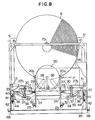
- the disk support portions 38 come into supporting the disk 6 and move upwardly to a position shown in Figs. 8 and 9 in which the center opening of the disk 6 is exposed to view and from which the disk 6 can be manually removed with ease.
- FIG. 8 another compact disk can be held at points S and S' by the thumb and index fingers and inserted in the disk loading mechanism, after the disk 6 is removed as aforesaid.
- the drive motor 57 By depressing the open/close button, the drive motor 57 is actuated to move the slider 35 and the elevation arms 32 downwardly by a process which is in reverse of the process described hereinabove with reference to disk unloading.
- the disk 6 inserted in this way first abuts against a disk seat 67 (shown in Fig. 2) on the back plate 10 to be positioned with respect to the vertical.
- the center opening of the disk 6 is eccentrically guided by the center spindle 70.
- the disk 6 slightly moves upwardly along an inclined surface of the disk guide 13, so that finally a gap is defined between the disk 6 and the disk seat 67 and the disk 6 is placed in condition for playing as shown in Figs. 2, 4 and 5.
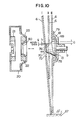
- Fig. 10 is a side view, with certain parts being shown in section, of the disk 6 and the disk guide 13 in explanation of the aforesaid process for placing the disk in condition for playing.
- the disk loading process will be described.
- the open/close button 2a shown in Fig. 1
- the drive motor 57 is actuated to rotate in a direction for closing the disk loading mechanism 5.
- the slider 35 F ig. 2 continues to move downwardly and stops in a position in which it clears the outer peripheral edge of the disk 6.
- an upper edge of the center opening 75 of the disk 6 is positioned against a first inclined surface 76 of the center spindle 70 and has at least a guide value g shown in Fig. 10.
- the disk seat 67 is provided in a position in which the aforesaid relation between the disk 6 and the center spindle 70. holds (condition I). From this condition, the disk 6 is moved as the disk clamper 23 and the clamp holder 20 move toward the disk 6, so that the central portion of the disk 6 tends to be forced against the center spindle 70. As the disk 6 is further pressed by the clamp holder 20 and the disk clamper 23, the disk 6 moves upwardly by an amount corresponding to h as shown in Fig.
- the outer periphery of the disk 6 is spaced apart from the disk seat 67 by a gap G'.
- the gap G ' corresponds to the value of h by which the disk 6 moves upwardly as the upper edge of the center opening 75 rides on the first inclined surface 76 plus the value of G by which the disk 6 moves upwardly as the . upper edge of the center opening 75 rides on the second inclined surface 78.
- the disk 6 is prevented from coming into contact with the disk seat 67 during rotation (condition III).
- condition III When the disk 6 is in condition III for playing, the magnet 18 and the magnet 22 on the disk clamper 23 attract each other to keep the disk 6 in position, while the magnet 22 and the magnet 21 on the clamp holder 20 repel each other.
- a guide wall 80 of the disk clamper 23 is in engagement with the vertical outer peripheral portion 77 of the disk guide 13 to hold the disk 6 in place and rotates with the disk 6, without coming into contact with any part within the clamp holder 20.
- the disk clamper 23 and the clamp holder 20 are first separated from the disk 6 from the position shown in Figs. 2, 4 and 5 in which the disk 6 is in condition for playing, as the disk loading mechanism is opened. Then, the center opening 75 of the disk 6 is released from the disk guide 13 and the center spindle 70 successively, as the disk 6 moves forwardly in pivotal movement while the outer peripheral edge of the disk 6 abuts against the inner wall surface of the back plate 10. Thereafter, the slider 35 shown in Fig. 2 moves in linear movement as the drive motor 57 rotates and the elevation arms 32 move upwardly in pivotal movement to lift the disk 6 held by the disk supports. 38 to positions shown in Figs. 7, 8 and 9.
- the disk in the disk loading and unloading system according to the invention, can be moved upwardly to a position in which the center opening thereof is exposed to view, after playing of the disk is finished, and the disk has only to be inserted in the player to this position when it is loaded.
- This enables the disk to be held at points S and S' by one hand in loading and unloading disk, without soiling or damaging the surfaces of the disk in which information is stored by hands that come into contact therewith.
- the accuracy with which the disk is automatically placed in condition for playing after loaded in the player by the disk loading and unloading system according to the invention is increased, and reliability of the system is improved because when the disk is loaded, the disk is moved downwardly and the upper edge of the center opening of the disk is first brought into contact with the first inclined surface of the disk guide with a predetermined guide value g and then the disk is correctly positioned at the center when the upper edge of the center opening is brought into contact with the second inclined surface of the disk guide. This eliminates the danger of the disk being damaged due to its failure to be correctly placed in position.
Landscapes
- Holding Or Fastening Of Disk On Rotational Shaft (AREA)
Applications Claiming Priority (4)
| Application Number | Priority Date | Filing Date | Title |
|---|---|---|---|
| JP57094968A JPS58212649A (ja) | 1982-06-04 | 1982-06-04 | デイスク導入装置 |
| JP57094969A JPS58212650A (ja) | 1982-06-04 | 1982-06-04 | デイスク装着脱装置 |
| JP94969/82 | 1982-06-04 | ||
| JP94968/82 | 1982-06-04 |
Publications (2)
| Publication Number | Publication Date |
|---|---|
| EP0096405A1 true EP0096405A1 (fr) | 1983-12-21 |
| EP0096405B1 EP0096405B1 (fr) | 1988-03-16 |
Family
ID=26436192
Family Applications (1)
| Application Number | Title | Priority Date | Filing Date |
|---|---|---|---|
| EP83105544A Expired EP0096405B1 (fr) | 1982-06-04 | 1983-06-06 | Système de chargement et déchargement de disque |
Country Status (3)
| Country | Link |
|---|---|
| US (1) | US4561084A (fr) |
| EP (1) | EP0096405B1 (fr) |
| DE (1) | DE3376038D1 (fr) |
Cited By (5)
| Publication number | Priority date | Publication date | Assignee | Title |
|---|---|---|---|---|
| WO1987000673A1 (fr) * | 1985-07-24 | 1987-01-29 | Deutsche Thomson-Brandt Gmbh | Dispositif de blocage pour disque compact sur platines a lecture verticale. |
| EP0369978A3 (fr) * | 1988-11-17 | 1990-11-14 | Staar Societe Anonyme | Dispositif de chargement d'éjection et de centrage pour disques de diamètres différents |
| EP0427531A3 (en) * | 1989-11-07 | 1992-04-29 | Mitsubishi Denki Kabushiki Kaisha | Disk cartridge loading/unloading system |
| RU2183359C2 (ru) * | 1996-05-02 | 2002-06-10 | Конинклийке Филипс Электроникс Н.В. | Загрузочный механизм для введения и выведения информационного диска в/из устройства информационной технологии |
| EP1562191A3 (fr) * | 2004-02-05 | 2007-08-22 | Raymedia Co. Ltd. | Lecteur de disque ultra-plat du type à fente |
Families Citing this family (17)
| Publication number | Priority date | Publication date | Assignee | Title |
|---|---|---|---|---|
| JPH023656Y2 (fr) * | 1984-10-23 | 1990-01-29 | ||
| JPS6286572A (ja) * | 1985-10-11 | 1987-04-21 | Alps Electric Co Ltd | デイスク回転装置 |
| AT384688B (de) * | 1986-03-07 | 1987-12-28 | Philips Nv | Aufzeichnungs- und/oder wiedergabegeraet mit einem zum aufnehmen eines aufzeichnungstraegers vorgesehenen aufnahmeraum |
| US4811323A (en) * | 1986-10-22 | 1989-03-07 | Staar S.A. | Apparatus for loading and unloading record disc player |
| US4939713A (en) * | 1987-02-27 | 1990-07-03 | Matsushita Electric Industrial Co., Ltd. | Erasable optical disk and optical information recording/reproduction apparatus |
| US5214635A (en) * | 1987-02-27 | 1993-05-25 | Matsushita Electric Industrial Co., Ltd. | Erasable optical disk and optical information recording/reproduction apparatus |
| BE1001388A6 (fr) * | 1988-03-02 | 1989-10-17 | Staar Sa | Mecanisme de centrage automatique de disques. |
| JP3761227B2 (ja) * | 1995-10-31 | 2006-03-29 | 三星電子株式会社 | ディスク装置 |
| JPH11126401A (ja) * | 1997-10-20 | 1999-05-11 | Sony Corp | 記録再生装置 |
| JP4071410B2 (ja) | 1999-11-12 | 2008-04-02 | パイオニア株式会社 | ディスクプレーヤ |
| TW459216B (en) * | 1999-11-18 | 2001-10-11 | Ind Tech Res Inst | Magnet attraction type automatic elevated disk pressing tool |
| US6816448B2 (en) * | 2001-06-07 | 2004-11-09 | Hewlett-Packard Development Company, L.P. | Door assembly for an optical drive |
| JP3884644B2 (ja) | 2001-11-22 | 2007-02-21 | 株式会社ディーアンドエムホールディングス | 光ディスク再生装置および再生方法 |
| US20040098735A1 (en) * | 2002-11-14 | 2004-05-20 | Lg Electronics Inc. | Disk loading apparatus for a disk drive |
| DE102005006752A1 (de) * | 2005-02-15 | 2006-08-17 | Robert Bosch Gmbh | Elektrisches Gerät |
| KR20100030065A (ko) * | 2008-09-09 | 2010-03-18 | 삼성전자주식회사 | 광 디스크 재생장치 |
| JP6114466B2 (ja) * | 2013-04-15 | 2017-04-12 | エナジウム リミテッド | 試験管グリッパー及びこれを含む試験管準備装置 |
Citations (5)
| Publication number | Priority date | Publication date | Assignee | Title |
|---|---|---|---|---|
| DE3116056A1 (de) * | 1980-04-22 | 1982-03-25 | Sharp K.K., Osaka | "schallplattenhaltevorrichtung fuer plattenspieler" |
| GB2088113A (en) * | 1980-07-30 | 1982-06-03 | Sharp Kk | Disc Record Player With Record Loading/Unloading Assembly |
| GB2093253A (en) * | 1980-08-13 | 1982-08-25 | Sharp Kk | Playing both sides of gramophone record |
| EP0070556A1 (fr) * | 1981-07-20 | 1983-01-26 | Kabushiki Kaisha Toshiba | Appareil d'entraînement de disque |
| EP0076061A1 (fr) * | 1981-09-18 | 1983-04-06 | Kabushiki Kaisha Toshiba | Appareil pour le chargement d'un disque sur le plateau d'un tourne-disques |
Family Cites Families (7)
| Publication number | Priority date | Publication date | Assignee | Title |
|---|---|---|---|---|
| GB234753A (en) * | 1925-02-19 | 1925-06-04 | Emma Siebert | Lasts |
| DE1245612B (de) * | 1961-11-06 | 1967-07-27 | Max Ernst | Plattenspieler mit Verschiebeeinrichtung zum Fuehren des Tonarmes |
| DE1221461C2 (de) * | 1965-05-07 | 1973-11-15 | Plattenspieler, bei dem die schallplatten durch einen schlitz des gehaeuses eingeschoben wird | |
| BE669161A (fr) * | 1965-09-03 | 1965-12-31 | ||
| DE2909099A1 (de) * | 1979-03-08 | 1980-09-11 | Licentia Gmbh | Abspielgeraet fuer eine bild- oder schallplatte |
| JPS55500729A (fr) * | 1980-03-24 | 1980-10-02 | ||
| JPS5850661A (ja) * | 1981-09-18 | 1983-03-25 | Toshiba Corp | ディスクロ−ディング機構 |
-
1983
- 1983-06-06 EP EP83105544A patent/EP0096405B1/fr not_active Expired
- 1983-06-06 US US06/501,154 patent/US4561084A/en not_active Expired - Fee Related
- 1983-06-06 DE DE8383105544T patent/DE3376038D1/de not_active Expired
Patent Citations (5)
| Publication number | Priority date | Publication date | Assignee | Title |
|---|---|---|---|---|
| DE3116056A1 (de) * | 1980-04-22 | 1982-03-25 | Sharp K.K., Osaka | "schallplattenhaltevorrichtung fuer plattenspieler" |
| GB2088113A (en) * | 1980-07-30 | 1982-06-03 | Sharp Kk | Disc Record Player With Record Loading/Unloading Assembly |
| GB2093253A (en) * | 1980-08-13 | 1982-08-25 | Sharp Kk | Playing both sides of gramophone record |
| EP0070556A1 (fr) * | 1981-07-20 | 1983-01-26 | Kabushiki Kaisha Toshiba | Appareil d'entraînement de disque |
| EP0076061A1 (fr) * | 1981-09-18 | 1983-04-06 | Kabushiki Kaisha Toshiba | Appareil pour le chargement d'un disque sur le plateau d'un tourne-disques |
Cited By (6)
| Publication number | Priority date | Publication date | Assignee | Title |
|---|---|---|---|---|
| WO1987000673A1 (fr) * | 1985-07-24 | 1987-01-29 | Deutsche Thomson-Brandt Gmbh | Dispositif de blocage pour disque compact sur platines a lecture verticale. |
| EP0369978A3 (fr) * | 1988-11-17 | 1990-11-14 | Staar Societe Anonyme | Dispositif de chargement d'éjection et de centrage pour disques de diamètres différents |
| BE1002664A3 (fr) * | 1988-11-17 | 1991-04-30 | Staar Sa | Dispositif de chargement, d'ejection et de centrage pour disques de diametres differents. |
| EP0427531A3 (en) * | 1989-11-07 | 1992-04-29 | Mitsubishi Denki Kabushiki Kaisha | Disk cartridge loading/unloading system |
| RU2183359C2 (ru) * | 1996-05-02 | 2002-06-10 | Конинклийке Филипс Электроникс Н.В. | Загрузочный механизм для введения и выведения информационного диска в/из устройства информационной технологии |
| EP1562191A3 (fr) * | 2004-02-05 | 2007-08-22 | Raymedia Co. Ltd. | Lecteur de disque ultra-plat du type à fente |
Also Published As
| Publication number | Publication date |
|---|---|
| US4561084A (en) | 1985-12-24 |
| DE3376038D1 (en) | 1988-04-21 |
| EP0096405B1 (fr) | 1988-03-16 |
Similar Documents
| Publication | Publication Date | Title |
|---|---|---|
| US4561084A (en) | Disk loading and unloading system | |
| US4592039A (en) | Disc player | |
| GB2126003A (en) | Disc carrying system | |
| KR850001456B1 (ko) | 오토 로우딩(auto-loading)장치 | |
| US5128918A (en) | Disk loading device for disk player | |
| EP0157588A2 (fr) | Appareil pour écrire et/ou lire sur des disques magnétiques | |
| US4063286A (en) | Video disc player | |
| NL8001704A (nl) | Magnetische registratie-weergeefinrichting. | |
| US4220339A (en) | Caddy-actuated declutching mechanism for video disc player | |
| EP0166381A2 (fr) | Appareil de transfert de données pour cartouche à disque magnétique | |
| JPS5860456A (ja) | オ−トロ−デイング機構 | |
| US4031557A (en) | Casette loading device for use in magnetic sound recording and playing back apparatus | |
| US4380783A (en) | Flexible disk drive | |
| JPS5860460A (ja) | 蓋開閉装置 | |
| US4694361A (en) | Data transfer apparatus having a simplified clamp mechanism for holding a disklike record medium in place | |
| JPH07240053A (ja) | ディスク装置のイマージェンシー・イジェクト機構 | |
| JPS62229567A (ja) | デイスクプレイヤ | |
| JP2677046B2 (ja) | ディスクチェンジャー装置 | |
| JPS647487Y2 (fr) | ||
| JPS6234009Y2 (fr) | ||
| US5889633A (en) | Cassette tape drive having an improved mechanism for opening and closing a tape cassette lid | |
| JPH0456380B2 (fr) | ||
| JPS626623Y2 (fr) | ||
| JPS6235174Y2 (fr) | ||
| KR850002765Y1 (ko) | 유연한 레코드 캐리어용 구동장치 |
Legal Events
| Date | Code | Title | Description |
|---|---|---|---|
| PUAI | Public reference made under article 153(3) epc to a published international application that has entered the european phase |
Free format text: ORIGINAL CODE: 0009012 |
|
| AK | Designated contracting states |
Designated state(s): DE FR GB IT NL |
|
| 17P | Request for examination filed |
Effective date: 19840504 |
|
| RBV | Designated contracting states (corrected) |
Designated state(s): DE GB |
|
| GRAA | (expected) grant |
Free format text: ORIGINAL CODE: 0009210 |
|
| AK | Designated contracting states |
Kind code of ref document: B1 Designated state(s): DE GB |
|
| REF | Corresponds to: |
Ref document number: 3376038 Country of ref document: DE Date of ref document: 19880421 |
|
| PLBE | No opposition filed within time limit |
Free format text: ORIGINAL CODE: 0009261 |
|
| STAA | Information on the status of an ep patent application or granted ep patent |
Free format text: STATUS: NO OPPOSITION FILED WITHIN TIME LIMIT |
|
| 26N | No opposition filed | ||
| PGFP | Annual fee paid to national office [announced via postgrant information from national office to epo] |
Ref country code: GB Payment date: 19900525 Year of fee payment: 8 |
|
| PGFP | Annual fee paid to national office [announced via postgrant information from national office to epo] |
Ref country code: DE Payment date: 19900726 Year of fee payment: 8 |
|
| PG25 | Lapsed in a contracting state [announced via postgrant information from national office to epo] |
Ref country code: GB Effective date: 19910606 |
|
| GBPC | Gb: european patent ceased through non-payment of renewal fee | ||
| PG25 | Lapsed in a contracting state [announced via postgrant information from national office to epo] |
Ref country code: DE Effective date: 19920401 |