EP0096413A2 - Dacheindeckungselement, insbesondere zur Gewinnung von Sonnenenergie - Google Patents
Dacheindeckungselement, insbesondere zur Gewinnung von Sonnenenergie Download PDFInfo
- Publication number
- EP0096413A2 EP0096413A2 EP83105583A EP83105583A EP0096413A2 EP 0096413 A2 EP0096413 A2 EP 0096413A2 EP 83105583 A EP83105583 A EP 83105583A EP 83105583 A EP83105583 A EP 83105583A EP 0096413 A2 EP0096413 A2 EP 0096413A2
- Authority
- EP
- European Patent Office
- Prior art keywords
- roofing element
- element according
- plate body
- lower apron
- roofing
- Prior art date
- Legal status (The legal status is an assumption and is not a legal conclusion. Google has not performed a legal analysis and makes no representation as to the accuracy of the status listed.)
- Granted
Links
Images
Classifications
-
- F—MECHANICAL ENGINEERING; LIGHTING; HEATING; WEAPONS; BLASTING
- F24—HEATING; RANGES; VENTILATING
- F24S—SOLAR HEAT COLLECTORS; SOLAR HEAT SYSTEMS
- F24S20/00—Solar heat collectors specially adapted for particular uses or environments
- F24S20/60—Solar heat collectors integrated in fixed constructions, e.g. in buildings
- F24S20/69—Solar heat collectors integrated in fixed constructions, e.g. in buildings in the form of shingles or tiles
-
- Y—GENERAL TAGGING OF NEW TECHNOLOGICAL DEVELOPMENTS; GENERAL TAGGING OF CROSS-SECTIONAL TECHNOLOGIES SPANNING OVER SEVERAL SECTIONS OF THE IPC; TECHNICAL SUBJECTS COVERED BY FORMER USPC CROSS-REFERENCE ART COLLECTIONS [XRACs] AND DIGESTS
- Y02—TECHNOLOGIES OR APPLICATIONS FOR MITIGATION OR ADAPTATION AGAINST CLIMATE CHANGE
- Y02B—CLIMATE CHANGE MITIGATION TECHNOLOGIES RELATED TO BUILDINGS, e.g. HOUSING, HOUSE APPLIANCES OR RELATED END-USER APPLICATIONS
- Y02B10/00—Integration of renewable energy sources in buildings
- Y02B10/20—Solar thermal
-
- Y—GENERAL TAGGING OF NEW TECHNOLOGICAL DEVELOPMENTS; GENERAL TAGGING OF CROSS-SECTIONAL TECHNOLOGIES SPANNING OVER SEVERAL SECTIONS OF THE IPC; TECHNICAL SUBJECTS COVERED BY FORMER USPC CROSS-REFERENCE ART COLLECTIONS [XRACs] AND DIGESTS
- Y02—TECHNOLOGIES OR APPLICATIONS FOR MITIGATION OR ADAPTATION AGAINST CLIMATE CHANGE
- Y02E—REDUCTION OF GREENHOUSE GAS [GHG] EMISSIONS, RELATED TO ENERGY GENERATION, TRANSMISSION OR DISTRIBUTION
- Y02E10/00—Energy generation through renewable energy sources
- Y02E10/40—Solar thermal energy, e.g. solar towers
Definitions
- the invention relates to a roofing element, in particular for the production of solar energy, made of plastic or the like. deformable material, with a flow channel provided in a plate body for a heat transfer fluid and with connection members formed at the ends of this flow channel for connecting the flow channels of the overlapping roof covering elements.
- Roof covering elements of this type that can be used as solar collectors (DE-Gm 76 13 567) are known. In shape and size they correspond to the usual roof tiles and are therefore interchangeable. As with another known roof tile (DE-OS 28 18 475), a cavity is formed for the flow of a medium to be heated, the flow lines being either pipes inserted into the tiles or channels. To connect these flow channels, the known roof tiles have approximately vertically downwardly directed connecting pieces which can be plugged into corresponding upward-facing connection openings of the covered roof tiles (DE-OS 25 29 095).
- this connector is neither when laying the pans can still be checked later, it is also difficult to make this connection tight due to lack of insight, especially since such a push-on connection does not offer the possibility of forming longer sealing walls. Furthermore, it often happens with this type of connection that the overlying pan remains in a slightly raised position and there is no longer a tight seal between the overlapping pans. In this case, rain dust and snowflakes can easily penetrate.
- this push-on connection is avoided in that the connections of the flow channels are formed by insertion bores running approximately in the direction of flow. Since a flexible intermediate pipe is to be used here, no insulating layer can be applied in this area. In unfavorable weather conditions, condensation can form here, which then drips into the roof space.
- the invention is therefore based on the object to provide a roofing element which prevents the dripping of condensation water and the passage of rain or snow particles.
- a roof covering element of the type mentioned at the outset according to the invention is characterized in that at the head end of a lower apron which extends under the connection covering element is formed and which extends at least to its recessed drain flattenings.
- This lower apron increases the overlap of the overlapping roof covering elements and thus forms a longer catch area for incoming rain and snow.
- the apron stretcher extends to that of one Insulating layer, then it also prevents condensation from dripping. This apron can be easily molded on during the manufacture of the roofing elements, especially if it is a plastic product.
- the roof covering element shown in the form of a roof tile has a plate body 1 with, for example, a central roller 2 and the longitudinal overlap and undergrip strips 3 and 4. In between are the plate flats 5.
- a flow channel 7 extends to the width of the actual plate body with the two flats 5 and the central roller 2. This flow channel is advantageously molded into the plate body, which is conveniently done by blow molding in a plate body made of plastic .
- a deformable plastic such as appropriately stabilized polypropylene, is particularly well suited for the production of such roofing elements.
- the other profiles can also be formed during blow molding train the top and bottom surface well and precisely.
- the lateral over and under gripping strips with their ribs, as well as the head and foot ribs 8, 9, can also be formed into hollow bodies.
- limiting beads 10, 11 are also formed along the lateral upper and lower gripping strips 3 and 4. Since these are located between the roof battens, they can be high enough to form a bed for receiving a thermal insulation material (not shown).
- the space between the overlap and undergrip strips 3 and 4 rising above the flow channel in the area of the slat support and covering sections is also filled with a heat insulating material.
- These insulating layers can be applied well and easily immediately after the plate bodies have been formed.
- the cavities formed are not used for the flow of the heat transfer medium, they can be filled with a further liquid or another filler in order to achieve a plate weight which essentially corresponds to a clay or concrete plate.
- a plug hole 15 is formed flush with this front edge in the apex of the center roll 2, while a further plug hole 16 is located at the foot end of the pan (FIG. 3). So that these plug-in bores lie, for example, in one plane and in a straight line with one another, the plug-in bore 16 is formed at the end of a connecting elbow 16 '. Both plug holes form the connecting elements of the flow channel 7. They are expediently aligned with one another on the longitudinal center line of the pan.
- a plug-in tube 17 is used, which carries on its two plug-in heads 18 fitted sealing rings 19, which, together with the plug-in holes made to fit, form a tight connection to let.
- the plug-in tube 17 is expediently flexible and of appropriate length in order to make the connection of the roof tiles easier and faster.
- the invention provides a lower apron 20 at the head end of the roof tile.
- This apron apron is advantageously 5 to 12 cm, advantageously 7 to 10 cm beyond the head side and extends at least to the area of the two pan flats 5 and the central roller 2, whereby it is passed below the plug tube.
- the lower apron expediently rises as high as the roof tiles allow. So that the condensation or other water collected by the lower apron runs off well, the transitions to the actual panel body rise slightly, which then still form a sufficient drainage slope in the installed position of a roof pitch. So that the foot ribs 9 of the covering roof tile engaging in the flattened areas do not impede the water drainage, drainage gaps (not visible) are expediently formed on these.
- the apron 20 since the apron 20 according to the invention also increases the overlap of the roof tiles and thus also the catching space for incoming rain and snow particles, it is not only suitable for the roof tile shown.
- the apron can be attached to any other roof panel and tile, including beaver tails or other plate-shaped roofing elements may be attached. It forms a real catch screen for each roof covering element with a plug-in bore 15 which is approximately the same as the element level and which can also protrude above the head end 14.
- the length of this lower apron 20 should be large enough, at least in the area of the plug connection, that it sufficiently engages under the plug bore 16 and possibly the connecting elbow 16 '.
Landscapes
- Engineering & Computer Science (AREA)
- Physics & Mathematics (AREA)
- Life Sciences & Earth Sciences (AREA)
- Sustainable Development (AREA)
- Sustainable Energy (AREA)
- Thermal Sciences (AREA)
- Chemical & Material Sciences (AREA)
- Combustion & Propulsion (AREA)
- Mechanical Engineering (AREA)
- General Engineering & Computer Science (AREA)
- Roof Covering Using Slabs Or Stiff Sheets (AREA)
Abstract
Description
- Die Erfindung betrifft ein Dacheindeckungselement, insbesondere zur Gewinnung von Sonnenenergie, aus Kunststoff od.dgl. verformbarem Werkstoff, mit einem in einem Plattenkörper vorgesehenen Durchflußkanal für eine Wärmeträgerflüssigkeit und mit an den Enden dieses Durchflußkanales ausgebildeten Anschlußorganen zur Verbindung der Durchflußkanäle der sich überdeckenden Dacheindeckungselemente.
- Als Sonnenkollektoren verwendbare Dacheindeckungselemente dieser Art (DE-Gm 76 13 567) sind bekannt. In der Form und Größe entsprechen sie den üblichen Dachpfannen und sind daher gegen diese austauschbar. Wie bei einem anderen bekannten Dachziegel (DE-OS 28 18 475) ist ein Hohlraum für den Durchfluß eines zu erwärmenden Mediums ausgebildet, wobei die Durchflußleitungen entweder in die Ziegel eingelegte Rohre oder auch Kanäle sein können. Zur Verbindung dieser Durchflußkanäle weisen die bekannten Dachpfannen etwa senkrecht zur Pfannenebene nach unten gerichtete Anschlußstutzen auf, die in entsprechende nach oben weisende Anschlußöffnungen der überdeckten Dachpfannen aufsteckbar sind (DE-OS 25 29 095). Abgesehen davon, daß sich diese Steckverbindung weder beim Verlegen der Pfannen noch nachträglich kontrollieren läßt, ist es auch schwierig, diese Anschlußverbindung wegen mangelnder Einsicht dicht zu machen, zumal eine solche Aufsteckverbindung keine Möglichkeit zur Ausbildung längerer Abdichtungswände bietet. Ferner kommt es bei dieser Verbindungsart häufig vor, daß die aufliegende Pfanne in leicht angehobener Stellung verbleibt und ein dichter Abschluß zwischen den sich überlappenden Pfannen nicht mehr gegeben ist. Regenstaub und Schneeflocken können in diesem Fall leicht eindringen. Bei einem anderen Dacheindeckungselement (EP-A 0 048 982) ist diese Aufsteckverbindung dadurch vermieden, daß die Anschlüsse der Durchflußkanäle von etwa in Strömungsrichtung verlaufenden Einsteckbohrungen gebildet sind. Da hierbei ein flexibles Zwischenrohr einzusetzen ist, kann in diesem Bereich keine Isolierschicht angebracht werden. Bei ungünstigen Witterungsverhältnissen kann sich hier Kondenswasser bilden, das dann in den Dachraum abtropft.
- Der Erfindung liegt daher die Aufgabe zugrunde, ein Dacheindeckungselement zu schaffen, das das Abtropfen von Kondenswasser sowie das Hindurchtreten von Regen- oder Schneeteilchen verhindert.
- Zur Lösung dieser Aufgabe ist ein Dacheindeckungselement der eingangs genannten Art gemäß der Erfindung dadurch gekennzeichnet, daß an seinem Kopfende eine das Anschluß-Eindeckungselement untergreifende Unterzugschürze ausgebildet ist, die sich zumindest auf seine vertieften Abfluß-Abflachungen erstreckt.
- Diese Unterzugschürze vergrößert die Uberlappung der sich überdeckenden Dacheindeckungselemente und bildet dadurch einen längeren Fangraum für eintretenden Regen und Schnee. Erstreckt sich die Unterzugschürze auf den von einer Isolierschicht freigehaltenen Abschnitt, dann verhindert sie auch das Abtropfen von Kondenswasser. Diese Unterzugschürze läßt sich bei der Herstellung der Dacheindeckungselemente ohne weiteres anformen, insbesondere wenn es sich um ein Kunststofferzeugnis handelt.
- Weitere Merkmale der Erfindung sind den Unteransprüchen zu entnehmen.
- Die Erfindung wird nachfolgend anhand eines Ausführungsbeispieles, das auch in der Zeichnung schematisiert dargestellt ist, näher beschrieben. Es zeigen:
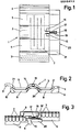
- Fig. 1 eine Draufsicht auf einen Kopfteil einer Dachpfanne,
- Fig. 2 eine Stirnansicht hierzu und
- Fig. 3 einen Schnitt durch die Enden von zwei sich überdeckenden Dachpfannen.
- Das dargestellte Dacheindeckungselement in Form einer Dachpfanne weist einen Plattenkörper 1 mit beispielsweise einer Mittelrolle 2 und den längsseitigen Ubergreif- und Untergreifleisten 3 und 4 auf. Dazwischen befinden sich die Platten-Abflachungen 5. Ein Durchflußkanal 7 erstreckt sich auf die Breite des eigentlichen Plattenkörpers mit den beiden Abflachungen 5 und der Mittelrolle 2. Dieser Durchflußkanal ist vorteilhaft in den Plattenkörper eingeformt, was zweckmäßig bei einem aus Kunststoff hergestellten Plattenkörper durch Blasformen geschieht.
- Ein verformbarer Kunststoff, wie entsprechend stabilisiertes Polypropylen, eignet sich besonders gut für die Herstellung solcher Dacheindeckungselemente. Beim Blasformen lassen sich auch die übrigen Profilierungen an der Ober- und Unterfläche gut und exakt ausbilden. So können neben dem Durchflußkanal auch die seitlichen über-und Untergreifleisten mit ihren Rippen, wie auch die Kopf-und Fußrippen 8,9 zu Hohlkörpern ausgebildet sein. Bei der gezeigten Dachpfanne sind längs der seitlichen über- und Untergreifleisten 3 bzw. 4 noch Begrenzungswulste 10, 11 ausgebildet. Da sich diese zwischen den Dachlatten befinden, können sie ausreichend hoch sein, um ein Bett zur Aufnahme eines Wärmeisolierstoffes (nicht gezeigt) zu bilden. Ebenfalls wird zweckmäßig auch der Raum zwischen den sich über den Durchflußkanal erhebenden Über- und Untergreifleisten 3 und 4 im Bereich der Lattenauflage- und Überdeckungsabschnitte mit einem Wärmeisolierstoff ausgefüllt. Diese Isolierschichten lassen sich unmittelbar nach dem Formen der Plattenkörper gut und einfach aufbringen.
- Soweit die ausgebildeten Hohlräume nicht für den Durchfluß des Wärmeträgermittels ausgenützt werden, können sie mit einer weiteren Flüssigkeit oder einem sonstigen Füllstoff gefüllt werden, um ein Plattengewicht zu erreichen, das im wesentlichen einer Ton- bzw. Betonplatte entspricht.
- Am Kopfende 14 der Dachpfanne ist im Scheitel der Mittelrolle 2 eine Steckbohrung 15 bündig mit dieser Stirnkante ausgebildet, während eine weitere Steckbohrung 16 sich am Fußende der Pfanne befindet (Fig.3). Damit diese Steckbohrungen beispielsweise in einer Ebene liegen und geradlinig miteinander fluchten,ist die Steckbohrung 16 am Ende eines Anschlußkrümmers 16' ausgebildet. Beide Steckbohrungen bilden die Anschlußorgane des Durchflußkanales 7. Sie sind zweckmäßig auf der Längsmittellinie der Pfanne aufeinander ausgerichtet. Zur Verbindung der Steckbohrungen 15,16 von zwei sich überdeckenden Pfannen dient ein Steckrohr 17, das an seinen beiden Einsteckköpfen 18 aufgezogene Dichtringe 19 trägt, die zusammen mit den auf Paßsitz gefertigten Steckbohrungen eine dichte Verbindung entstehen lassen. Das Steckrohr 17 ist zweckmäßig flexibel und von entsprechender Länge, um die Verbindung der Dachpfannen leichter und schneller herstellen zu können.
- Am kanalfreien Pfannen-Fußende und insbesondere im Bereich der Steckverbindung ist eine Wärmeisolierung nicht leicht anzubringen und aus wärmetechnischen Gründen auch nicht erwünscht, weil dann die überdeckende Dachpfanne die aufgenommene Wärme auf den darunterliegenden Durchflußkanal der überdeckten Dachpfanne übertragen kann. An diesem nicht isolierten Abschnitt bildet sich aber bei ungünstigen Witterungsverhältnissen Kondenswasser, das auf die darunter angeordnete Dachhaut oder in den Dachraum abtropft. Um dies zu vermeiden, sieht die Erfindung eine Unterzugschürze 20 am Kopfende der Dachpfanne vor. Diese Unterzugschürze steht zweckmäßig 5 bis 12 cm, vorteilhaft 7 bis 10 cm über die Kopfseite hinaus und erstreckt sich mindestens auf den Bereich der beiden Pfannenabflachungen 5 und der Mittelrolle 2, wobei sie unterhalb des Steckrohres hindurchgeführt ist. An den Seitenrändern 21 steigt die Unterzugschürze zweckmäßig so weit hoch, wie es die Abdeckung der Dachpfannen zuläßt. Damit das von der Unterzugschürze aufgefangene Kondens- oder sonstige Wasser gut abläuft, sind die Übergänge zum eigentlichen Plattenkörper leicht ansteigend, die dann in der verlegten Stellung einer Dachneigung noch eine ausreichende Abflußschräge bilden. Damit die in die Abflachungen eingreifenden Fußrippen 9 der überdeckenden Dachpfanne den Wasserablauf nicht behindern, sind an diesen zweckmäßig Abflußspalten (nicht sichtbar) ausgebildet.
- Da durch die erfindungsgemäße Unterzugschürze 20 auch die Uberlappung der Dachpfannen und damit auch der Fangraum für eintretende Regen- und Schneeteilchen vergrößert wird, ist sie nicht nur für die dargestellte Dachpfanne geeignet. Die Unterzugschürze kann vielmehr an jeder anderen Dachplatte und jedem Dachziegel, auch an Biberschwänzen oder sonstigen plattenförmigen Dacheindeckungselementen angebracht sein. Sie bildet für jedes Dacheindeckungselement mit einer zur Elementen-Ebene etwa gleichlaufenden Steckbohrung 15, die auch über das Kopfende 14 vorstehen kann, einen echten Auffangschirm. Die Länge dieser Unterzugschürze 20 soll mindestens im Bereich der Steckverbindung so groß sein, daß sie die Steckbohrung 16 und eventuell den Anschlußkrümmer 16' ausreichend untergreift.
Claims (8)
Priority Applications (1)
| Application Number | Priority Date | Filing Date | Title |
|---|---|---|---|
| AT83105583T ATE21966T1 (de) | 1982-06-07 | 1983-06-07 | Dacheindeckungselement, insbesondere zur gewinnung von sonnenenergie. |
Applications Claiming Priority (2)
| Application Number | Priority Date | Filing Date | Title |
|---|---|---|---|
| DE3221490 | 1982-06-07 | ||
| DE3221490A DE3221490C2 (de) | 1982-06-07 | 1982-06-07 | Dacheindeckungselement zur Gewinnung von Sonnenenergie |
Publications (3)
| Publication Number | Publication Date |
|---|---|
| EP0096413A2 true EP0096413A2 (de) | 1983-12-21 |
| EP0096413A3 EP0096413A3 (en) | 1984-05-02 |
| EP0096413B1 EP0096413B1 (de) | 1986-09-03 |
Family
ID=6165561
Family Applications (1)
| Application Number | Title | Priority Date | Filing Date |
|---|---|---|---|
| EP83105583A Expired EP0096413B1 (de) | 1982-06-07 | 1983-06-07 | Dacheindeckungselement, insbesondere zur Gewinnung von Sonnenenergie |
Country Status (3)
| Country | Link |
|---|---|
| EP (1) | EP0096413B1 (de) |
| AT (1) | ATE21966T1 (de) |
| DE (1) | DE3221490C2 (de) |
Cited By (3)
| Publication number | Priority date | Publication date | Assignee | Title |
|---|---|---|---|---|
| GB2198759A (en) * | 1986-12-12 | 1988-06-22 | David Turner Coates | Solar heat collecting cladding component |
| ITTO20100213A1 (it) * | 2010-03-19 | 2011-09-20 | Cosmogas Srl | Tegola per tetti di edifici con mezzi di conversione dell'energia solare |
| EP1927814B1 (de) * | 2006-11-29 | 2012-02-29 | Ideasol S.r.l. | Fliese zur Verwendung von Sonnenenergie |
Families Citing this family (4)
| Publication number | Priority date | Publication date | Assignee | Title |
|---|---|---|---|---|
| AT399190B (de) * | 1987-12-15 | 1995-03-27 | Vanovsek Wolfgang Dipl Ing Dr | Sonnenkollektor |
| DE4011289A1 (de) * | 1990-04-06 | 1991-01-03 | Joachim Kahle | Keramikglas-sonnenkollektoren zur einarbeitung in dachziegeln herkoemmlicher formen und typen |
| DE19603540A1 (de) * | 1996-02-01 | 1997-08-07 | Bernhard Ehret | Dacheindeckungselement |
| US10547270B2 (en) | 2016-02-12 | 2020-01-28 | Solarcity Corporation | Building integrated photovoltaic roofing assemblies and associated systems and methods |
Family Cites Families (4)
| Publication number | Priority date | Publication date | Assignee | Title |
|---|---|---|---|---|
| DE2640333A1 (de) * | 1976-09-08 | 1978-03-09 | Harald Martin Schmelow | Kollektorpfanne |
| EP0032667A1 (de) * | 1980-01-16 | 1981-07-29 | Hoechst Aktiengesellschaft | Wärme-Absorber als Teil von Gebäude-Aussenflächen |
| DE3038472A1 (de) * | 1980-10-11 | 1982-05-27 | Hoechst Ag, 6000 Frankfurt | Waerme-absorber als teil von gebaeude-aussenflaechen |
| DE3036897A1 (de) * | 1980-09-30 | 1982-04-22 | Hans 6507 Ingelheim Weitzel | Dacheindeckungselement aus kunststoff o.dgl. verformbarem werkstoff zur gewinnung von sonnenenergie |
-
1982
- 1982-06-07 DE DE3221490A patent/DE3221490C2/de not_active Expired
-
1983
- 1983-06-07 EP EP83105583A patent/EP0096413B1/de not_active Expired
- 1983-06-07 AT AT83105583T patent/ATE21966T1/de not_active IP Right Cessation
Cited By (4)
| Publication number | Priority date | Publication date | Assignee | Title |
|---|---|---|---|---|
| GB2198759A (en) * | 1986-12-12 | 1988-06-22 | David Turner Coates | Solar heat collecting cladding component |
| GB2198759B (en) * | 1986-12-12 | 1991-02-06 | David Turner Coates | Cladding component. |
| EP1927814B1 (de) * | 2006-11-29 | 2012-02-29 | Ideasol S.r.l. | Fliese zur Verwendung von Sonnenenergie |
| ITTO20100213A1 (it) * | 2010-03-19 | 2011-09-20 | Cosmogas Srl | Tegola per tetti di edifici con mezzi di conversione dell'energia solare |
Also Published As
| Publication number | Publication date |
|---|---|
| ATE21966T1 (de) | 1986-09-15 |
| EP0096413B1 (de) | 1986-09-03 |
| EP0096413A3 (en) | 1984-05-02 |
| DE3221490C2 (de) | 1986-01-09 |
| DE3221490A1 (de) | 1983-12-08 |
Similar Documents
| Publication | Publication Date | Title |
|---|---|---|
| DE60220760T2 (de) | Solarpaneelanordnung | |
| EP0131249B1 (de) | Fluiddichte gelenkige Verbindung zwischen Hohlprofilen | |
| DE69723507T2 (de) | Sprosse | |
| DE69703456T2 (de) | Modulrinne für Abflusskanäle | |
| DE3712867A1 (de) | Wasserfangschale | |
| EP0048982B1 (de) | Dacheindeckungselement aus Kunststoff zur Gewinnung von Sonnenenergie | |
| DE1708992A1 (de) | Ablaufrinne,insbesondere fuer ziegelgedeckte Daecher | |
| EP0000543A2 (de) | Bausatz für Klimadächer oder Klimafassaden und seine Verwendung als Verdampfer | |
| EP0096413A2 (de) | Dacheindeckungselement, insbesondere zur Gewinnung von Sonnenenergie | |
| EP0288020B1 (de) | Firstbohle mit aufliegendem Firstabdichtungs- und Belüftungselement | |
| DE2929215C2 (de) | Rahmen für einen Solarkollektor | |
| DE19745883C1 (de) | Sonnenkollektor | |
| DE2724224C3 (de) | Dränelement für die Herstellung von als Hohlwand ausgebildeten Dränsträngen sowie eine aus Dränelementen gebildete Bodenentwässerungsanlage | |
| DE1805768B2 (de) | Kunststoff dachrinne | |
| DE3729738A1 (de) | Dachkonstruktion mit hohlen keramikbloecken | |
| CH661084A5 (de) | Dach mit sich schuppenartig ueberdeckend angeordneten dachdeckungselementen. | |
| DE2814707C3 (de) | Lüftungsöffnungen aufweisender Firstziegel - | |
| DE3001249C2 (de) | ||
| DE2514241A1 (de) | Installationskanal aus kunststoff | |
| DE2141499A1 (de) | Belueftbares gehaeuse | |
| DE2931945A1 (de) | Waermeschutzabdeckung | |
| DE8318374U1 (de) | Belagbelag zur verwendung bei aussenflaechen von gebaeuden oder freianlagen | |
| DE20121297U1 (de) | Solarkollektor-Gehäuse | |
| DE19713718C1 (de) | Dachziegel | |
| DE1509117C (de) | Ortgangverkleidung für Flachdächer |
Legal Events
| Date | Code | Title | Description |
|---|---|---|---|
| PUAI | Public reference made under article 153(3) epc to a published international application that has entered the european phase |
Free format text: ORIGINAL CODE: 0009012 |
|
| AK | Designated contracting states |
Designated state(s): AT BE CH FR GB IT LI NL |
|
| PUAL | Search report despatched |
Free format text: ORIGINAL CODE: 0009013 |
|
| AK | Designated contracting states |
Designated state(s): AT BE CH FR GB IT LI NL |
|
| 17P | Request for examination filed |
Effective date: 19840905 |
|
| GRAA | (expected) grant |
Free format text: ORIGINAL CODE: 0009210 |
|
| AK | Designated contracting states |
Kind code of ref document: B1 Designated state(s): AT BE CH FR GB IT LI NL |
|
| REF | Corresponds to: |
Ref document number: 21966 Country of ref document: AT Date of ref document: 19860915 Kind code of ref document: T |
|
| ITF | It: translation for a ep patent filed | ||
| ET | Fr: translation filed | ||
| PLBE | No opposition filed within time limit |
Free format text: ORIGINAL CODE: 0009261 |
|
| STAA | Information on the status of an ep patent application or granted ep patent |
Free format text: STATUS: NO OPPOSITION FILED WITHIN TIME LIMIT |
|
| 26N | No opposition filed | ||
| PGFP | Annual fee paid to national office [announced via postgrant information from national office to epo] |
Ref country code: GB Payment date: 19910613 Year of fee payment: 9 |
|
| ITTA | It: last paid annual fee | ||
| PG25 | Lapsed in a contracting state [announced via postgrant information from national office to epo] |
Ref country code: GB Effective date: 19920607 |
|
| GBPC | Gb: european patent ceased through non-payment of renewal fee |
Effective date: 19920607 |
|
| PGFP | Annual fee paid to national office [announced via postgrant information from national office to epo] |
Ref country code: FR Payment date: 19970627 Year of fee payment: 15 |
|
| PGFP | Annual fee paid to national office [announced via postgrant information from national office to epo] |
Ref country code: NL Payment date: 19970630 Year of fee payment: 15 Ref country code: AT Payment date: 19970630 Year of fee payment: 15 |
|
| PGFP | Annual fee paid to national office [announced via postgrant information from national office to epo] |
Ref country code: BE Payment date: 19970711 Year of fee payment: 15 |
|
| PGFP | Annual fee paid to national office [announced via postgrant information from national office to epo] |
Ref country code: CH Payment date: 19970723 Year of fee payment: 15 |
|
| PG25 | Lapsed in a contracting state [announced via postgrant information from national office to epo] |
Ref country code: AT Free format text: LAPSE BECAUSE OF NON-PAYMENT OF DUE FEES Effective date: 19980607 |
|
| PG25 | Lapsed in a contracting state [announced via postgrant information from national office to epo] |
Ref country code: LI Free format text: LAPSE BECAUSE OF NON-PAYMENT OF DUE FEES Effective date: 19980630 Ref country code: CH Free format text: LAPSE BECAUSE OF NON-PAYMENT OF DUE FEES Effective date: 19980630 Ref country code: BE Free format text: LAPSE BECAUSE OF NON-PAYMENT OF DUE FEES Effective date: 19980630 |
|
| BERE | Be: lapsed |
Owner name: WEITZEL HANS Effective date: 19980630 |
|
| PG25 | Lapsed in a contracting state [announced via postgrant information from national office to epo] |
Ref country code: NL Free format text: LAPSE BECAUSE OF NON-PAYMENT OF DUE FEES Effective date: 19990101 |
|
| REG | Reference to a national code |
Ref country code: CH Ref legal event code: PL |
|
| PG25 | Lapsed in a contracting state [announced via postgrant information from national office to epo] |
Ref country code: FR Free format text: LAPSE BECAUSE OF NON-PAYMENT OF DUE FEES Effective date: 19990226 |
|
| NLV4 | Nl: lapsed or anulled due to non-payment of the annual fee |
Effective date: 19990101 |
|
| REG | Reference to a national code |
Ref country code: FR Ref legal event code: ST |